IRJET- Prospects of Inland Water Transportation in the River Drainage System of Kashmir
•
0 likes•28 views

This document discusses the potential for developing inland water transportation along the Jhelum River in Kashmir, India. It conducted a hydrographic survey of a 27 km stretch of the Jhelum River from Pampore to Chattabal to assess navigation feasibility. The survey found the river width varies from 40-210 meters and depth ranges from 0.4-13.6 meters below chart datum, indicating potential for passenger vessel transport. However, encroachments and pollution have reduced the river's capacity and a detailed design plan would be needed to restore it for regular inland water transportation.

Recommended
Recommended
More Related Content
What's hot
What's hot (18)
Similar to IRJET- Prospects of Inland Water Transportation in the River Drainage System of Kashmir
Similar to IRJET- Prospects of Inland Water Transportation in the River Drainage System of Kashmir (20)
More from IRJET Journal
More from IRJET Journal (20)
Recently uploaded
Recently uploaded (20)
IRJET- Prospects of Inland Water Transportation in the River Drainage System of Kashmir
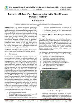
- 1. International Research Journal of Engineering and Technology (IRJET) e-ISSN: 2395-0056 Volume: 06 Issue: 06 | June 2019 www.irjet.net p-ISSN: 2395-0072 © 2019, IRJET | Impact Factor value: 7.211 | ISO 9001:2008 Certified Journal | Page 2673 Prospects of Inland Water Transportation in the River Drainage System of Kashmir Maleeha Rashid1 PG Scholar, Department of Civil Engineering, Desh Bhagat University, Punjab, India ---------------------------------------------------------------------***---------------------------------------------------------------------- Abstract – There is an immense potential of inland water transportation as an alternate transportationinKashmir. The major consideration for such a linkage is navigation on river. This energy efficient and environment friendly mode of transport system got defunct after alternative modes of road and rail networks came to fore with quick movement and several other facilities. Current Traffic estimation and envisaged traffic and passenger forecast was taken into consideration .Moreover, detailed design of waterway, passenger vessel and terminalsontheprojectedtrafficvolume. Comparative Tariff analysis for IWT and other services providing adequate motivation to adopt IWTbyuser. Toknow the existing condition of river, hydrographic survey was conducted between Pampore and Chattabal. Key Words: Inland Water Transportation, Hydrographic survey, Vessel Design, Dredging, River drainage system, 1. Introduction Considering the present traffic congestion, frequent jams, narrow roadways in Srinagar city and for restoration of fast mode of transportation and glory of river Jhelum, in the first phase a length of 27 km from Pampore to Chattabal weir within Srinagar city can be used as a public Water transport system. Keeping in -view the physical constraints of the sharpest bend near Batwara and the size of vessel that can ply in the waterway, the river bed has been kept1.1mbelow SLWL throughout the width of the river. Considering the waterway features, physical constraintsinthe waterwaylike bridges, the traffic demand during the peak hour and also keeping in view the local ethos and environment, the vessel is designed. The traffic forecasts in respect of passengers & tourist traffic have been used as the basis for the functional planning of the terminals in an optimal way.An environmental impact assessment study has been carried out to ascertain the impact of development of the waterway on the ecosystem. Organizational setup to run the IWT was suggested and worked out consideringthetotal requirement of operation and maintenance. Inland water transportation may also help in mitigatingthechancesofprospectivefloods. Following have been done to carry out the study: Traffic estimation and forecast. Detailed design of waterway, passenger vessel and terminals on the projected traffic volume. Fix competitive tariff for IWT and other services providing adequate motivation to adopt IWT by user. Evaluate and propose the IWT system with best economic and financial 1.2. Potential of Inland Water Transport in Kashmir Valley The length of navigable waterways in the State of Jammu & Kashmir exceeds 200 kms. Most of the rivers flowing in the Jammu province have a steep gradient and are therefore not suitable for navigation. Except fora few ferry crossingsinthe lower reaches of the Chenab, there is hardly any water transport in the Jammu Province. In Kashmir valley, River Jhelum is the principal waterway and is important from navigational point of view. The prospects of development of IWT exist in the following stretches of the Jhelum River and the lakes inKashmirvalley: i. Pampore to Chattabal on River Jhelum ii. Khanbal to Baramulla on River Jhelum. iii. Khudawain to Sangam on Vishow River. iv. Duderhama to Shadipora on the Sindh River. v. Vodhpora to Oabgah (Sopore) on Pelssu Nallah. vi. Tail reaches on some other tributaries. vii. Dal, Nigeen, Manasbal & Wular Lakes. 2. River Jhelum- An Overview Satellite View – River Jhelum The Jhelum River, called as the life line of Kashmir, originates from the Pir Panchal mountain ranges in the south eastern part of thevalley.Theriveroriginatesfrom a spring, Verinag,located at the foothillsofPirPanchal.It
- 2. International Research Journal of Engineering and Technology (IRJET) e-ISSN: 2395-0056 Volume: 06 Issue: 06 | June 2019 www.irjet.net p-ISSN: 2395-0072 © 2019, IRJET | Impact Factor value: 7.211 | ISO 9001:2008 Certified Journal | Page 2674 acts as a perennial source forthe river. Theriveralsohas a non-perennial source at Vyethvathru nallah, located a few kilometres away from Verinag. 2.1 The original glory of Jhelum About 100 years back or so, much of the Internal Commerce of Kashmir depended on river Jhelum. It was said that, “If Egypt is the gift of Nile, then Kashmir is the gift of Jhelum”. There is no other instance of a valley, other than Kashmir, situated at an altitude of 5000 ft. above sea level, having a broad river, intersecting it for so long a distance. Out of its total course of 720 km, about 320 km lie within the Pakistan territory. Below its junction with Kishenganga, Jhelum forms the boundary between the Kashmir state and Pakistan districts of Hazana and Rawalpindi and finally joins Chenab at Trimmu. The lengthfromitssourcetoBaramullais 240 km while as from Khanabal to Baramulla it is 163 km. The river and its tributaries have also been the main source of irrigation of the valley, which owes its lush greenery tothe river waters. 2.2. Encroachments and Pollution Encroachments along the river banks The river Jhelum, once considered as the life line of Kashmir, whose crystal clear waters and charming beauty had a soothing and mesmerising effect on the mind and soul has been gradually turned into an open sewer. As a result of unabated pollution and choking of the river due to encroachments at various places along the banks, it has lost its original, pristine glory. The hydrology of River Jhelum is largely controlled by melting of snow in the spring and the Indian monsoons that bring heavy rains from June to September. The highest flood discharges on the Jhelum exceed28,300m3/s.Littlerainfalls during the winter, so the river level is substantially lower than in summer months. During floods, the channel becomes filled and starts overflowing the banks. When the flood rises above the banks, it overflows and causes damage to life and property in the adjoining areas. Number of encroachments on the right side of Jhelum: 676 Number of encroachments on the left side of Jhelum: 525 Number of encroachments removed: 500 3. Hydrographic Survey 3.1. General Hydrographic survey is the basic requirement for determining the existing condition of river. It reveals the feasibility of improving the waterway for navigation by selected craft or in deciding the craft suitable for the waterway. For conducting the hydrographic survey, ground control (horizontal and vertical) are very essential. The topographic survey was conducted to delineate banks, channel and other ground features. 3.2. Methodology Study area falls in the 'Restricted Zone’ of Survey of India Maps and Triangulation Data. The topographic survey was started with Reconnaissance Survey andan AutoLevel was used forrunning the traverse and fixing the control points. With the help of fixed control points on the guide bund of river, planimetry survey was conducted for delineating the ground features. Leveling work was done with the help of an Auto Level with known bench mark for fixing temporary bench mark and water level at X-section. Cross-section of flow channel at suitable intervals, not exceeding 200 m on a straight and 100 m where river turns/meanders its course. A single longitudinal profile of river bed along deeper course was recorded. Current measurements at three locations viz. at U/S end, mid-way and D/S end of study reach was conducted during survey period. Three gauges were establishedatsuitablelocationsand connected with BM to determine the water level. All details of bridges,lockgatesandweirwerecollected. 4-5 sediment/bed samples were collected at 2-3 locations on river Jhelum and analyzed for grain size distribution and other properties. 3.3. Topographic Survey Due to the study area falling in 'Restricted Zone' of SOI Maps and Triangulation Data, traverse was started taking origin marked on a cemented pillar of Ferry Ghat at Kadlabal on right bank of Jhelum and assuming coordinate30,000mEast and 10,000 m North. An open traverse was run along the river coarse for fixing the horizontal control point for planimetry with the help of precision theodolite. All precautions were taken to ensure the accuracy and
- 3. International Research Journal of Engineering and Technology (IRJET) e-ISSN: 2395-0056 Volume: 06 Issue: 06 | June 2019 www.irjet.net p-ISSN: 2395-0072 © 2019, IRJET | Impact Factor value: 7.211 | ISO 9001:2008 Certified Journal | Page 2675 permissible errors were adjusted. All topographical details were picked up with the help of control points by plane table method. 3.4. Hydrographic Survey In the study reach, i.e., from Pampore to Chattabal, the width of the river channel varies from 45 m to 210 m and almost 90% stretch of the river was exposed during survey period. Cross sections at an interval of not exceeding 200 m on straight and 100 m where river takes turn/meanders were taken using conventional methods andinstrumentslikerope, sounding pole, tapes etc. The soundings were taken with the help of a tape and sounding pole. Thalweg surveys were carried out from Kadlabal to Chattabal along the deeper course of the waterway. 3.5. Hydrological Observations Long period hydrological observations such as water levels, discharge, flow velocities are very essential to study the water potentiAality for introduction of navigation and to fix the standard low water level/chart datum for reduction of soundings. Data of the past ten years for discharge andwater levels (monthly maximum & minimum) at Pampore, Ram Munshi Bagh & Chattabal gauge sites were collected from P&D Division of Kashmir Irrigation and Flood Control Department, Srinagar. To knowtheexistingflowofwaterand water gradient, waterlevelobservationatthreelocations,i.e., Pampore, Zero bridge and Chattabal were established and recorded at a timeinterval of 30 min.Currentobservationsat gauge sites, Pampore, Zero Bridge and Chattabal were conducted. 3.6. Choice of Chart Datum For clear depiction of the river bed, soundings have to be expressed with reference to a selected chart datum. Chart Datum/StandardLowWaterLevel(SLWL)isareferencelevel close to lowest flow level and selected in such a way that the water level will seldom fall below it. Therefore, depth shown on the chart shall be available normally throughout the year for navigation. The basic principle behind the adoption of a chart datum/SLWL is to have a reAalistic picture of the river bed with reference to a known plan to facilitate comparison of the past with present survey and assess the changes in the river bed. SLWL / chart datum cannot be horizontal but will be sloped to get a realistic picture of the depth. Thus, for this study, sloped chart datum has been selected. 3.7. Description of Waterway The Jhelum River, called as the lifeline of Kashmir,originates from the Pir Panchal mountain ranges in the south eastern part of the valley. The river originates from a spring, Verinag, located at the foothills of Pir Panchal. It acts as a perennial source forthe river. Theriveralsohasanon-perennialsource at Vyethvathru Nallah, located a few kilometres away from Verinag. When the river Jhelum flows out of Verinag, it is just a trickle. The majesty it acquires later is mainly due to a number of glacier-fed tributaries contributing their waters to it. At Khanabal it is joined by six mountain streams namely Sandran, Bringi, Arapath,Veshav,RambiaraandLidder.Later on it is joined by Romshi, Sindh, Doodh Ganga, Ferozepur nallah and Pohru. The river flows through Srinagar and Wular Lake before entering Pakistan. The Kishenganga (Neelum river), the largest tributary of Jhelum joins it at Muzaffarabad. The next largest tributary, the KunharRiver, joins it in Kaghan valley. It is thenjoinedby the PoonchRiver and flows into the Mangla Dam reservoirin the district of Mirpur. The JhelumentersPunjabintheJhelum district. It ends in a confluence with river Chenab. The Chenab then merges with Sutlej which then joins the Indus River. Some believe the name of the river, that is, Jhelum is derived from the words Jal (pure water) and Ham (snow). Stillothers believe that its namehas been derivedfromthecityofJhelum in Punjab province through which the river flows. It is called as Vitasta in Sanskrit and Hydaspes in ancient Greek. The Vitasta is believed to have been one of the major seven rivers mentioned in the holy scriptures of the Indo-Aryans, the Rigveda. The name survives in Kashmiri as Vyeth. River Jhelum in the stretch of Pampore to Chattabal is navigable throughout the year due to the ponding effect created by the Chattabal weir. 3.7.1. Pampore to Panthachowk (Lasjan Byepass Bridge) (9.4 km) The waterway of this reach is normally 50 m to 100 m wide and depth of water below chart datum in mid-stream is varying from 0.4 m to 5.5 m. This waterway is crossed over by two bridges, i.e., Kadlabal and Jhelum Bridge (PRC) near Lasjan. Under these bridges 3.27 m/4.8 m & 6.06 m/5.39 m vertical clearance is available over Highest Flood Level / Dominant Flood Level respectively.Thisareaisnormallyfree from movement of house boats. 3.7.2. Lasjan to Zero Bridge (11 km) The channel width of this reach is 60 m to 100manddepthof water below chart datum in mid-section is varying from 0.4 to 13.6 m. In the stretch of Batwara to Zero Bridge, river flows in confined banks and banks are protected at sharp bend by wooden piling and retaining wall. U/S ofZeroBridge house boats are moored on both banks. Provision exists for spill channel/flood channel to control the floods in city area, start at left bank of river at ch.17.00 km and meet river again at D/S of Chattabal Weir.
- 4. International Research Journal of Engineering and Technology (IRJET) e-ISSN: 2395-0056 Volume: 06 Issue: 06 | June 2019 www.irjet.net p-ISSN: 2395-0072 © 2019, IRJET | Impact Factor value: 7.211 | ISO 9001:2008 Certified Journal | Page 2676 3.7.3. Zero Bridge to Chattabal Weir (7.3 km) The waterway in this reach varies from 40 m to 120 m and depth below chart datum varies from 1 m to 5.5 m except some shallow patches near Habba Kadal, Zaina Kadal, & Aali Kadal. Both the banks of river in this area are thickly populated. House boats are chained on both banks on this section. This waterway is crossed by 12 bridges viz. Zero Bridge (DST), Abdullah bridge (PRC), Amira Kadal (PRC), Budshah Kadal (DST), Habba Kadal (old DST & new under construction/PRC), Fateh Kadal (PRC), Zaina Kadal (old DST & new PRC), Aali Kadal (Steel), Nawa Kadal (PRC/DST) and Safa Kadal (PRC). River passes through main SrinagarCity.In this reach, banks are stable and houses are constructed on the bank of the river. Some ghats (stone/RCC) are built up by habitants and used for washing the clothes and other domestic use. Abandoned bridges piers could be seen in the waterway near U/S of Amira Kadal and U/S of Zaina Kadal. A spill channel Called Kut Kulstartsat D/S ofOldSecretariaton the left bank and meets the river flow at U/S of Safa Kadal on left bank. Connecting nallah called Chunti Kul takes off from river Jhelum U/S of Zero Bridge and meetsagainonrightside of river Jhelum at Dubji Ghat. 3.8. Restriction of Bridges/Lock gates imposed on Waterway There are several bridges crossing the Jhelum River within study area which facilitate the road network traffic. Most of them impose vertical/horizontal restrictions for free movement under the bridge above DFL/HFL. 3.9. Crossing of Power Line / Telephone Line 39 power lines/telephone lines cross the proposed waterway. Most of them do not have the vertical clearance between lowest conductor and HFL/ DFL for safenavigation. Hence they need to be removed. 4. Waterway 4.1 Channel Dimensions The chapter ‘Hydrographic Survey’ described hydrographic and hydraulic features of the waterway as it exists and the various restrictions by way of permanent structures for navigation. It is necessary to improve the existing waterway for uninterrupted two-way navigation for transporting the projected passenger and tourist traffic. 4.1.1 Waterway Design The basic parameters considered for the waterway design are: a) Depth b) Width c) Side slopes a) Depth of channel The waterway depth should be good enough to ensure steer ability of the vessel and to prevent bottom feel. To meet this requirement, the minimum depth that is needed in a channel will commonly be the sum of the draught (draft) of thevessel and other tolerance factors. The tolerance factors to be considered are listed as: Factor of keel clearance to avoid touching of the vessel to the ground and minimum free water below the keel for maintaining maneuvering controllability. Wave tolerance for the heaving and pitching of the vessel due to wave motion. Squat, increase of draft due to vessel motion. Tolerance for siltation and dredging. Increase of draught due to trim and heaving due to unequal loading and steering maneuver respectively. The keel clearance factor is the prime concern of the all tolerance factors considered. A 30 cm layer of water column below the keel of the loaded vessel is sufficient for free maneuverability of thevessel.InJhelumRiverwheresiltation of the channel is presumed to be moderate, an additional depth of 15 cm will provide the required tolerance. The clearance for other tolerance factors such as squat, trim, heaving etc. is small and thereby their impact is minor. However, an additional clearance of 5 cm has been provided to counter these factors. By considering the above standard norms, a total clearance of 50 cm below the draught of the vessel is provided. The draught of the vessel considered for the waterway is 0.6 m. Thechanneldepth,thus,becomes1.10 m below Standard Low Water Level. b) Width of channel The width of channel depends on: Dimensions of largest vessel considering their lengths, widths, drafts and displacements as well as stopping distances, maneuvering characteristics, anchoring equipments. Depth of channels, under keel clearance, allowances forvessel motion, sideslopeeffectsandinaccuracies in dredging and measurements. Waterway channel layout and turns. Widths for passing, maneuvering, turning circles. Navigation Aids and communication along the waterway channel. The total width (W) of a two-way navigation waterway is expressed as: W = BM + BM1 + C + 2C1 Where; W = Navigation channel width for two way navigation.
- 5. International Research Journal of Engineering and Technology (IRJET) e-ISSN: 2395-0056 Volume: 06 Issue: 06 | June 2019 www.irjet.net p-ISSN: 2395-0072 © 2019, IRJET | Impact Factor value: 7.211 | ISO 9001:2008 Certified Journal | Page 2677 BM = Maneuvering zone for the design vessel which takes into account the directional stability of vessel. BM1 = Maneuvering zone for the upcoming vessel which takes into account the directional stability of vessel. C = Width of separating zone. C1 = Width of the security area, between the manoeuvring zone and the channel side which is accountedforenvironmentalandhumanfactorsincluding bank section. Values recommended by various authorities for the above equation vary within widelimits.Someoftherecommended values are presented here: BM = 1.3 B to 3.0 B BM = BM1 C = 0.5 B to 1.0 B C1 = 0.3 B to 1.5 B where; B = Max. Width of design vessel. The factors considered for the present design are: B = 3.4 m BM = 1.3 B BM = BM1 C = 0.5 B C1 = 0.45 B Therefore, design channel width = 1.3 B + 1.3 B + 0.5 B + 2x 0.45 B = 4B = 13.6 m ~ 14 m c) Side Slopes The selection of slopes is in accordance with the soil characteristics of the bed and banks, width of the waterway, etc. The bed material of Jhelum River between Pampore and Chattabal is mainly composed of fine sand and silty clay. Hence, the adopted channel slope is 3:1. The designed channel dimensions with adopted slope are: Bed width = 14 m Depth below SLWL = 1.1 m Side slope = 3:1 The channel width at draft level thus becomes 20.6 m. The guidelines proposed by Delft Hydraulics for waterway design in normal and narrow reaches and the present waterway design criteria are given in the following table. Table -1: Waterway Design Criteria Criterion Delft Hydraulics guidelines for normal cross sections Design cross section adopted for Jehlum Waterway H/Ts 1.4 1.83 Bt/Bs 4.0 4.0 Vmax (km/h) 10.0 14.0 Where; H = Water depth Ts = Draft Bt = Width of waterways at draft level (or keel level) Bs = Width of vessel Vmax = Maximum speed of the vessel. The above table reveals that the design criteria adopted for the waterway of Jhelumrivergenerallyexceedstheminimum prescribed limitsbyDelftHydraulics.Assuchthechannelwill be suitable forthe vessel speed of the order of 14 to 15km/h. 4.1.2 Width allowance at bends At bends, the width of the waterway should be more thanthe width of the channel to allow for drift of the vessel at curved portions of the waterway. It means that the vessel occupies a greater width at bends than in a straight stretch of the waterway. The drift of the vessel dependsontheradiusofthe bend, the speed of the vessel, wind forces, the flow pattern and the loading of the vessel.The impact of the water flowon maneuvering vessel in driftingitspositionisnotsignificantin Jhelum River. The drift angle is larger for vessels traveling in the downstream than the - upstream direction. The drift angle is inversely proportional to the bend radius 'R', i.e., larger the radius, smaller the value of drift angle. Unloaded vessel is normally subjected to more drift and consequently takes up a greater width at bends than a loaded vessel and therefore the proposed allowance at the keel level of the unloaded vessel is larger than the loaded vessel. The guidelines for width allowance at bends proposed by Delft Hydraulics are as follows: Type of cross section Minimum Radius permitted Normal cross section R/L = 6 Narrow cross section R/L = 4
- 6. International Research Journal of Engineering and Technology (IRJET) e-ISSN: 2395-0056 Volume: 06 Issue: 06 | June 2019 www.irjet.net p-ISSN: 2395-0072 © 2019, IRJET | Impact Factor value: 7.211 | ISO 9001:2008 Certified Journal | Page 2678 Where; L = Length of design vessel (15.3 m) R = Radius of bend The Jhelum Waterway is not straight and has many sharp bends, the radius of the sharpest bend being 100 m. Wherever the radius of the bend is less than 6 times of the length of the designed vessel i.e. 6x15.3=91.8 or say 100m, additional widths are considered for free maneuverability of the vessel. The additional width considered in the present waterway system for designed vessel is: B = nL2/2R = 2 x (15.3)2/2 x 100 = 2.34 say 2.5 m 4.1.3 Dredging 4.1.3.1 Capital Dredging The river bed shall be dredged all along its width from Pampore to Chattabal so as to ensure minimum bed level as 1.1 m below SLWL. This dredging will ensure the maximum flood carrying capacity thus rescuing the inhabitants of the recurring threat of floods aswell. The totalquantityofcapital dredging that will be required to be carried out is estimated as 1523512.85 cum. 4.1.3.2 Maintenance Dredging Even after completion of the capital dredging project, the navigational channel will be subjected to re-siltation due to several factors, some of which are highlighted below: The rivers from the mountainous region carry silt, sand and when they reach the plains, the velocity of flow decreases and hence the silt is deposited. Erosion of banks in narrowstretchesduetoactionof wind, rain and waves caused by movement of powered boats and crafts. Dumping of wastes, spillages of cargo etc. In order to assess the quantity of maintenance dredging to clear the effect of such re-siltation with a fair degree of accuracy, hydrographic survey should be conducted at regular intervals for few years after the completion of the capital dredging project. However, for the purpose of cost estimates, the quantity may be taken as 10% of the capital dredging quantities based on past data on similar projects. 4.2 Characteristics of material to be dredged In order to assess the type of bed material to be dredged, limited soil investigation was carried out for sediment / bed samples taken at 3 - 4 places in river Jhelum. The analysis of samples showed that the material is mostly sand of poor gradation except in some cases where it is silty clay between Zero Bridge and Chattabal. The suspended silt load in water is negligible. The median grain size of the bed material is 0.2 to 0.6 mm. The following table describes the grain-size analysis and Atterberg Limits of the samples so obtained: a) Grain size distribution (%age): S. No. Location Sand Silt & Clay Coarse Medium Fine 1. Kadlabal, Pampore 12 86 2 - 2. Abdullah Bridge - - 2 98 3. Chattabal Weir - - 4 96 Remarks: Sand: Coarse = 4.76 to 2 mm Medium = 2 to 0.6 mm Fine = 0.6 to 0.075 mm Total fines (silt and clay): Below 0.075 mm b) Atterberg Limits: S. No. Location L.L. P.L. P.I. Texture 1. Kadlabal, Pampore Medium Sand 2. Abdullah Bridge Silt predominant with a little of clay 3. Chattabal Weir Silt predominant with a little of clay 4.3 Protection of River Banks 4.3.1 General considerations The navigational route in the proposed Jhelum River (Pampore to Chattabal) has a unique feature, which is morphologically different from the other usual riverine system. The velocities in the channel are considerably less with an average current of the order of 0.2 to 0.5 m/sec. Geo- technical characteristics of the river bed show that the soil is composed of mostly medium sand with tracesofsiltclay.The median grain size of the material is about 0.2 to 0.6 mm. Therefore, it appears that thebanksarenotmuchsusceptible to erosion by natural surface current. However, bank erosion couldoccurduetothefastmovement of mechanized vessels in the narrow stretches. Moving
- 7. International Research Journal of Engineering and Technology (IRJET) e-ISSN: 2395-0056 Volume: 06 Issue: 06 | June 2019 www.irjet.net p-ISSN: 2395-0072 © 2019, IRJET | Impact Factor value: 7.211 | ISO 9001:2008 Certified Journal | Page 2679 vessels generate waves and turbulence of different magnitude depending upon the speed of the vessel, its hull form, type and spacing ofpropellers,draftandriverbedform. The effects of these waves and turbulence on the channel cross section, including the stability of the sides depends upon the width of the channel and the relative cross-section of the vessel and the channel.Further whenavesselmovesin a confined channel, the return flow of water is caused by the water displacedalong the vesselside.Theextentofthereturn flow depends upon the velocity of the craft and can cause intensive suction effect on the banks affecting the sideslopes of the soil. The channel bed gets disturbed by the impact of propeller jet. Apart from causing instability of the banks, these effects also create silting of the navigational channel. 4.3.2 Vessel induced waves The erosion of channel bed and bank material is not only due to the natural currents but also due totheimpactofhydraulic load produced by the vessel-induced water motion. The vessel-induced water motioninturndependsuponthevessel type, channel geometry and sailing course in the waterway. The vessel-induced water motion can be divided into: a) Screw race b) Primary wave c) Secondary wave a) Screw race The turbulence in water and the consequent generation of currents due to propeller rotation of the vessel is known as screw race. The level of damage is proportional to both the screw race velocity and the duration over which the channel bed is exposed to the screw race. Therefore the areas susceptible to screw race damage are the places where the vessel maneuvering is at slow speed. The screw race velocities (Ub) corresponding to the vessel speed (Vs) are as follows: Vs (m/sec) 0 1 2 Ub (m/sec) 2.5 2.0 1.5 The design vessel speed for proposed study reach is 14 km/h. The screw race velocity for a design vessel with 14 km/h speed will be of about 1.0 to 1.2 m/sec. The impact of screw race on the channel bed is likely to be more in the approaches of terminals,locks, bends etc. where the speedof the vessel will be reduced. b) Primary wave The primary waves produced by the moving vessel can be divided into the following 3 types. return current water level depression transversal stern wave c) Secondary waves Secondary vessel waves are composed of transverse and diverging waves, which together produceinterferencepeaks. The interference peaks generally occur by small and fast sailing vessels and cause considerable damage to the banks. The secondary waves generated by theself-propelledvessels are of minor importance andhence no attention is to be paid. The design technique of the bank protectionworksshouldbe based on the impactofvariousvesselinducedhydraulicloads as stated above in combination with the natural flow phenomena in the waterway. 4.3.3 Existing Protection Work The study reach is already provided with some bank protection by Flood ControlDepartment of J&K.Twotypesof protections are adopted. The first type consists of stone boulder pitching, retaining walls and second type consists of wooden piling so that earth behind can be retained. From Zero Bridge to Chattabal, river banks have been encroached upon by construction of houses, shops and mooring of the house boats. Landscaping is required in these areas. Provision for rehabilitation of these encroachers has been envisaged in the project. 4.4 Aids to Navigation Various aids to navigation require to be provided to identify the waterway for safe navigation. The study reach of Jhelum River is planned to be providedwiththeseaidstofacilitate18 hours navigation. There are various types of marks fixed on banks and moored into the channel bed on both sides of the waterway to guide the vessel. Navigational marks are to be selected in such a way so as to suit the morphological conditions of the waterway system. The following four types of aids to navigation are considered for this study reach. Permanent Concrete Posts (Shore marks) Floating Buoys (lighted/unlighted) Temporary Stakes (Wooden/Concrete) Local arrangement under bridge (lighting for night navigation and danger marks) 4.5 Restriction of Bridges imposed on Waterway Fourteen road bridges existingacrosstheriverJhelumwithin the study area have restrictions for safe navigation above DFL. Special precautionshavetobeobservedforrunningsafe navigation near dominant flood level. One way navigation is recommended under the bridges. 5. TERMINALS 5.1. Basic Considerations The basic factors considered in the planning of the IWT
- 8. International Research Journal of Engineering and Technology (IRJET) e-ISSN: 2395-0056 Volume: 06 Issue: 06 | June 2019 www.irjet.net p-ISSN: 2395-0072 © 2019, IRJET | Impact Factor value: 7.211 | ISO 9001:2008 Certified Journal | Page 2680 terminal for handling the passenger and cargo traffic are as follows: Total cargo / passenger traffic Composition of cargo Density-wise classification of traffic. Permissible berth occupancies Seasonal / peak values of traffic 5.2. Operating Period In general, 330 days operation per year is assumed for terminal planning. For planning of terminals on this waterway, the operating number of days is taken as 300 per year. This provides sufficientmargininequipmentratingsfor meeting certain peak capacity requirement duringperiodsof congestion at terminals caused by holidays, climate extremities, stoppage periods etc. Considering the peculiar geographical location of Jhelum River where the extreme climatelasts normally for 2 months, only 300 days operation is considered feasible in one year. The system evaluated on this basis will be adequate to meet the operational contingencies incident in round the year operation of such terminals. The terminals have been designed to cater to the basic needs of passenger traffic. The roofing systems of the building have been so planned that it matches with the surroundings. Separateaverage area for cargo loading/unloading/storage have been planned and earmarked for future development. 5.3. Selection of Terminal Facilities Considering the traffic composition the infrastructural facilities required formeeting thetrafficatterminallocations for the respective time horizons are carried out. The terminals are planned next to either existing bridges or bridges under construction, considering the convenience of passengers residing on either side of river. 5.4. Transit Shed Considering the movement of passenger traffic to and from the berth and loading and unloading of barges as a transport chain, it is necessary that certain covered shed with ticketing facility, waiting hall, refreshmentfacilityandtoiletfacilityare provided for meeting the inclement weather requirements. 5.5. Location and Description of Terminals The list of proposed terminals and existingfacilitiesavailable in the proposed waterway on river Jhelum are detailed out. The terminal location, type of construction, facilities available/facilities to be provided, development works to be taken up in different phases etc. are described as follows: 5.6. Proposed Terminals Based on the norms and guidelines discussed above, it is proposed to provideterminals at the following 12 sitesalong the waterway: 1. Pampore 2. Pantha Chowk 3. Batwara 4. Zero Bridge 5. Badshah Bridge 6. Habba Kadal 7. Fateh Kadal 8. Zaina Kadal 9. Ali Kadal 10. Nawa Kadal 11. Safa Kadal 12. Chattabal Detailed description of the terminal facilities is given in the following paragraph: 5.6.1. Pampore The proposed terminal site is located at Chainage 1.17 km assuming 0 Chainage as centre line of Kadalbal (under construction) of the study area and on the right bank of the river. The site is well connected to the national highway. The land is to be acquired from Tahsildar office area. Steps on natural ground on compacted soil are proposed to be provided to facilitate the passenger movement. The floating barge would be pulled up with steel wire rope/chainsatHFL. P.C.C. flooring will be provided at the terminal. The top level of the bund will be at elevation RL 1591.10 m. The H.F.L. and SLWL are 1580.5 m and 1562.19 m respectively at the terminal location. 5.6.2. Pantha Chowk The terminal location is at Ch. 9.25 km approximately on the right bank of the Jhelum river. The terminal is adjacent to the Bye-'pass bridge. Govt. land is to be acquired for terminal development works.Aslopingbundfrom1588.38to1582.02 is being proposed with stone pitching. Steel chains are being proposed to pull the floating barge as per variation of water level. The HFL and SLWL are 1588.01 m and 1581.58 m respectively at this terminal location. 5.6.3. Batwara The proposed site for terminal is at Chainage 15 km approx. on the right bank of the river. The terminal is well connected to the nearby national highway.Privatelandistobeacquired. A 19.5 m longsteel gangwayisproposedleadingtostationery floating barge. P.C.C. floor is being recommended with floor finish level at RL 1588.11 m. The H.F.L. and S.L.W.L. at the terminal spot are 1587.81 m and 1581.12 m respectively.
- 9. International Research Journal of Engineering and Technology (IRJET) e-ISSN: 2395-0056 Volume: 06 Issue: 06 | June 2019 www.irjet.net p-ISSN: 2395-0072 © 2019, IRJET | Impact Factor value: 7.211 | ISO 9001:2008 Certified Journal | Page 2681 5.6.4. Zero Bridge Terminal Station –Zero Bridge The terminal is located at Chainage 20 km approx. on the left bank of the river. The proposed terminal is adjacent to the Abdullah Bridge (i.e. New Zero Bridge). The location is approx. 200 m away from zero bridge. A bund 40 m long is proposed. The existing staircasefromAbdullahBridgecanbe used for approaching this bund. A 27 m long gangway is proposed at the end of bund to cater to the vertical water level fluctuations. The highfloodlevelandlowwaterlevelare 1587.80 m and 1580.69 m respectively. The terminal floor finish level has been kept at 1588.10 m which is higher than the H.F.L. at the proposed terminal location. This location of terminal would provide aneasyapproachtopassengersfrom adjoining areas on either side of the bridge. 5.6.5. Budshah Bridge The proposed site for terminal is at Chainage 22.50 km approx. on the right bank of the river. The terminal site is located on Govt. land. In view of the strategic location of this terminal, it has the potential to be developed as a passenger- cum-cargo terminal in future when IWT is developed in the JhelumRiver from Anantnag to Baramulla.Itisalsoproposed to acquire land for cargo storage in future when the cargo traffic picks up. The terminal is adjacent to the road which is well connected to Badshah Bridge and Amira Kadal. A 27 m long steel gangway is proposed to negotiate the vertical water level variation. This gangway would be leading to a stationery floating barge. PC.C. flooring is proposed for the terminal The high flood level and standard low water level are 1587.6 m and 1580.5 m respectively. The terminal floor finish level will be at RL 1587.90 m. 5.6.6. Habba Kadal Old Habba Kadal Site The proposed terminal is located at chainage 23.70 km approx. on the left bank of the river. The site is well connected to the road network. A ticketing room, refreshment stall, toilets and passenger shed are being proposed. Concrete flooring will be proposed for terminal area. A 7 m concrete jetty is proposed leading to a sloping RCC stair case parallel to river.Afloatingbargeisproposedto be placed adjacent to stair case for passenger to board the vessels. The high flood level and lowwaterlevelare1587.5m and 1580.4 m respectively. The terminal floor level will be fixed at RL 1587.8 m keeping in view the high flood level. 5.6.7. Fateh Kadal Fateh Kadal The proposed terminal is at Ch. 24.50 km approx. on the left bank of the river. The terminal area is heavily inhabitant along the bank with permanent built up structures. The Government land is available for the terminal. The scheme proposed comprises of a small RR masonry platform, an 8 m long RCC jetty and a sloping stair case from RL 1587.90 to 1580.70. A barge is proposed to be placed parallel to the RCC sloping staircase. P.C.C. flooring is proposed at the decklevel RL 1587.7 m. The HFL and SLWL are 1587.4 m and 1580.36 m respectively at the berthing face. 5.6.8. Zaina Kadal The terminal is proposed at Ch. 25.0 km approx. on the left bank of the river. Government land is available for the terminal. A scheme with floating barge which would be
- 10. International Research Journal of Engineering and Technology (IRJET) e-ISSN: 2395-0056 Volume: 06 Issue: 06 | June 2019 www.irjet.net p-ISSN: 2395-0072 © 2019, IRJET | Impact Factor value: 7.211 | ISO 9001:2008 Certified Journal | Page 2682 laterally piled up at high water level is proposed. The bankto be suitably pitched with RR masonry is also proposed. PCC flooring will be provided on the top of terminal area. Both side of the terminal needs bank protection. The deck level will be at RL 1587.34 m. The HFL and SLWL are 1587.14 m and 1580.32 m respectively at the berthing zone. Zaina Kadal 5.6.9. Aali Kadal The proposed siteforthe terminal is situated at Ch. 25.45km approx. on the left bank of the river. The scheme proposed comprises of a small RR masonry platform, an 8 m long RCC jetty and a sloping stair case from RL 1580.72 to 1587.60. A barge is proposed to be placed parallel to the RCC sloping stair case. The arrangement for electricandwatersupplywill be provided forpassenger facility.ThedecklevelwillbeatRL 1587.35 m. The HFL and SLWL are 1587.05 m and 1580.285 m respectively at the berthing area. Aali Kadal 5.6.10. Nawa Kadal The terminal location will be at Ch. 25.80 km approx on the right bank of the river. A 15m long gangway supported on pile cap and floating barge is proposed. Bank protection is required on either side of the terminal. PCC flooring is recommended on the top of the deck. The electricity and water supply arrangement will be suitably developed for the public convenience and terminal operation. The top level of deck will be fixed at RL 1587.27 m. The HFL and SLWL are 1586.97 m and 1580.25 m respectively at the berthing zone. Nawa Kadal 5.6.11. Safa Kadal The proposed terminal will be at Ch. 26.50 kmapprox. onthe right bank of the river. A 23 m long steel gangway supported on pile cap on one side and floating barge on other side is proposed. Government land is available forthe terminal.The terminal is well connected to the nearby road. Bank will be protected on the either side of the terminal. Random rubble masonry wall would be provided on either side of the retaining wall to reduce the length of RCC retaining wall. The top of the terminal deck will be atRL1587.13m.TheHFLand SLWL are 1586.83 m and 1580.015 m respectively at the terminal area. Safa Kadal
- 11. International Research Journal of Engineering and Technology (IRJET) e-ISSN: 2395-0056 Volume: 06 Issue: 06 | June 2019 www.irjet.net p-ISSN: 2395-0072 © 2019, IRJET | Impact Factor value: 7.211 | ISO 9001:2008 Certified Journal | Page 2683 5.6.12. Chattabal The proposed terminal site will be at Ch.27.25kmapprox.on the right bank of the river. The proposed terminal is on piled approach jetty along with gangway. Government land is available for the terminal building. PCC flooring is being suggested forthe deck of the terminal. The top levelwillbeat RL 1587.13 m. The HFL and SLWL are 1586.83 m and 1580.015 m respectively at the terminal zone. Suitable arrangement for electric and water supply will be developed for public convenience. Chattabal Weir Facilities like ticketing room, maintenance room, toilets and passenger sheds are proposed to be provided on each terminal. Some life saving equipment will be provided at the every terminal keeping in view the passenger safety consideration. 6. ENVIRONMENTAL IMPACT ASSESSMENT 6.1 Environmental Regulations In pursuance of the global goals of nature conservation and protection, to which Indiaiscommittedsinceitsparticipation in Stockholm Conference, State Governments have initiated plans,schemes andactions toimplementvariouslegislations and regulations. In J&K, there is an increasing pressure on its resources. This has resulted in depletion and degradation of natural resources owing to the rapidly growing population. However, there is a growingawarenessamongpolicymakers and the public about effects of environmental degradation. Following Acts, Regulations and Documents were consulted for the preparation of this chapter: Water (Prevention and control of pollution) Act 1974. Amended in 1978 and 1988. Air (Prevention and control of pollution) Act 1981 Amended 1988. J&K Forest (Conservation) Act 1990. J&K Wildlife Act (1978). Forestry (Conservation) Act 1980, Amended in 1988. Environment Protection Act (1986). Guidelines for rail/road/highway project, MOEF, Govt. of India (1989) the latest being the Environmental (Protection)Act1986oftheMinistry of Environmental and Forest (MOEF). With rapid strides in economic development the need for rationalizingthetransportsystembecomesimperative.Inthe process of development, there has been an intensive use of the natural resources which has adversely affected the environment, leading to ecological imbalances. The importance of conserving and enhancing the environmental assets has assumed urgency. It is in this context that Initial Environmental Examination (IEE) of a navigable river is planned as per Environmental Protection Act (1986). 6.2 Physiography and Meteorology The project is situated in Kashmir Valley. The entire route of IWT passes through main stream of Jhelum River. The total length between Pampore to ChattabalWeirisabout27.6kms (Zero chainage taken as centre line of Kadlabal). Extreme variation in climate is observed in project area, owing to its location and topography. Theclimaticconditions in the project area are characterized by three seasons as: Rainy season ApriltoNovember Winter season November-March Summer season April-August Meteorological data recorded at nearby stations of Srinagar has indicated variation during the year. The mean annual rainfall in the area varies from 500 mm to 1150 mm. The highest temperature recorded is about 34.6°C and lowest - 7.8°C. Relative humidity varies from 71 to 88 percent. The meteorological data has been utilized to compute air quality in the area. 6.3 Geology and Soils The studies carried out in past have reported the geology from prehistoric to recent unconsolidated alluvial deposits comprising of silt, sand andclayandtheirmixtureindifferent proportions. The sediments are overlain by boulders/ pebbles of upper Shiwalik formations. The soil mainly consists of sand, silt and clay. The texture is sandy clay.
- 12. International Research Journal of Engineering and Technology (IRJET) e-ISSN: 2395-0056 Volume: 06 Issue: 06 | June 2019 www.irjet.net p-ISSN: 2395-0072 © 2019, IRJET | Impact Factor value: 7.211 | ISO 9001:2008 Certified Journal | Page 2684 S.No. TEXTURE VALUE RANGE (%) 1. Sand 41.2-56.1 2. Silt 19.5-20.1 3. Clay 23.8-39.3 6.4 Flora and Fauna J&K is known forits floraandfauna.ThereisnoNationalPark or Wildlife Reserve in the vicinity of the study area. 80% of the stretch is inhabited while about 20% stretch has tree/vegetation. Thus, no loss of forest area is anticipated by this project. The main vegetation species observed in this area are Chinar and Willow. About 10,015 tonnes of fish production is reported in Kashmir valley and 6000 fishermen are engaged in this activity. 6.5 Noise Noise too is responsible for adverse impact on physical and mental health of the people. The other impacts are: hearing impairment, communication interference, sleep disruption, and migration of wildlife The noise levels in the area may vary during day and night as 52 dB and 40 dB respectively. These values are below the prescribed International Standards. NOISE LEVEL STANDARDS Location Noise levels (dB) Day Night Industrial – Mixed 75 70 Commercial 65 55 Residential 55 45 Sensitive 50 40 6.6 Environmental Impacts Based on project particulars and existing environmental conditions, potential negative impacts have been identified and wherever possible these have been quantified. Negative impacts likely to result from the proposeddevelopmenthave been discussed in this section: Impacts due to project location. Impacts due to project construction and operation. 6.6.1 Impact due to Project Location Those impacts, which are likely to take place due to the layout of the project, have been assessed. The projectwillnot pose any displacement of the people (in case there is any, suitable rehabilitation facilities will be provided), loss to cultural monumentsandreligiousstructures.Theanticipated impacts are: a) Change in land use. b) Drainage and utilities problems. c) Jetty inlets and outlets, d) Lighting, and e) Terminal refuses. a) Change in Land use: The route is planned through the Jhelum River. The traffic would consist mainly of cargo and passengers. Terminals will have landing structure, waiting shed, toilet blocks, parking space and cargo storage area. The land required at different terminals is reported in the table below: LAND REQUIRED AT TERMINALS S.No. Terminals Area required (m2) 1 Pampore 378.5 2 Pantha Chowk 295.0 3 Batwara 300.0 4 Zero Bridge 240.0 5 Budshah Bridge 231.0 6 Habba Kadal 279.0 7 Fateh Kadal 150.0 8 Zaina Kadal 204.0 9 Ali Kadal 113.0 10 Nawa Kadal 216.0 11 Safa Kadal 162.0 12 Chattabal 436.5 Total 3005.0 m2 In all, about 0.3 ha of land is likely to be utilized to accommodate terminal buildings and other infrastructure. The area to be acquired will partly fall in agricultural land. The utilization of above land is negligible in comparison to available land and hence won’t have any adverse effect. b) Drainage and Utilities Problems:Themaindrainage in the catchment area is through rivers. The addition of transport vessels will not change the drainage patternof the area nor will it create any hindrance in utilities available in the area. c) Jetty-Inlets and Outlets: In the Project Report, 20 to
- 13. International Research Journal of Engineering and Technology (IRJET) e-ISSN: 2395-0056 Volume: 06 Issue: 06 | June 2019 www.irjet.net p-ISSN: 2395-0072 © 2019, IRJET | Impact Factor value: 7.211 | ISO 9001:2008 Certified Journal | Page 2685 40 m long and 3 m wide steel jetty is envisaged. To accommodate the passengers and cargo, a 3 m wide passage will be appropriate. About 300 - 400 Sqm land area is estimated for operational and service requirements on each station. In normal operating conditions, the jetty areas are designed to accommodate 2 to 3 persons per Sqm. The designed facilities are adequate. From these, it can be concluded that all the jetties have necessary provisions for space to accommodate people in normal as well as emergency conditions. Hence no hazard is anticipated due to proposed sizes of inlets and outlets. d) Lighting: The jetty and approach areas both on ground and in water will have adequate and uniform fluorescent lighting to provide pleasant and cheerful environment. Where electricity is not available the illumination shall be by solar lights. The ferry boats will be fitted with extra lamps to light up the landing pontoon. e) Terminal Refuse: The collection and removal of refuse in a sanitary manner from jetty/terminal stations are of importance for effective vector control, aesthetic improvement and nuisance and water pollution abatement. The refuse from terminals/jetty includes: Garbage, Rubbish, and Floor Sweeping. Due to non-availability of solid waste data for such facilities, it is assumed that about 20 gm per person per day will be generated. About 100peopleperterminalare likely to visit/work. The total refuse generated at all terminals will thus be about 2 tonnes/year. 6.6.2 Impacts due to Project Construction and Operations Although environmental hazards related to construction works are mostly of temporary nature, this does not mean that these should not be considered. The main issues which need attention are soil erosion, pollution and health risk. Runoff from unprotected excavated areas can result in excessive soil erosion, especially when the erodability of soil is high. Mitigation measures include careful planning, timing of cut-and-fill operations and revegetation. Health risks include disease hazards to people from lack of sanitation (water supply, human waste disposal) and insect- vector disease hazards to the local population. Mitigation measures should include proper water supply, sanitation, drainage, health care and human waste disposal facilities. In addition to these, efforts need to be made to avoid water spills and adopt disease control measures. The project may cause the following negative impacts due to the construction and operation: a) Oil Pollution, b) Noise, c) Accidental Hazards, d) Water Demands, e) Dredging, f) Water Quality, g) Impact on Aquatic Ecology, and h) Impact on Rare and Endangered Species. 6.7 Environmental Management Plan The Inland WaterTransportprojectwillprovideemployment opportunities, enhancement in career opportunities, enhancement of mobility, easy Inter-State movement and reduced energy consumption on one hand, but will create problems of soil disposal due to dredging, problems for marine habitat and water pollution, on the other. The environmental issues likely to develop during project construction and operation phases could be minimized by making necessary provisions in project design and adopting Environmental Management Plan (EMP). The most reliable way to ensure that the Environment Management Plan is integrated into the overall project planning and implementation is to establish the plan as a component of the project. This will ensure that the plan will receive funding and supervision along with the other investment components. Foroptimal integration ofEMPinto the project, these should be linked for: Funding, Management and Training, Monitoring. The purpose of the first is to ensurethatproposedactionsare adequately financed. The second link helps in imparting training, technical assistance;staffing and other institutional strengthening items needed to implement the mitigation measures in the overall management plan. The third link is necessary to provide a critical patch forimplementationand, to enable sponsors and the funding agency to evaluate the success of mitigation as part of project supervision and as a means to improve future project. Environment managementplanshavebeendevelopedforthe
- 14. International Research Journal of Engineering and Technology (IRJET) e-ISSN: 2395-0056 Volume: 06 Issue: 06 | June 2019 www.irjet.net p-ISSN: 2395-0072 © 2019, IRJET | Impact Factor value: 7.211 | ISO 9001:2008 Certified Journal | Page 2686 following negative impacts: Change of land use, Spills of Oil and Grease, Refuse and Waste, Disposal of Dredged Material, Noise Pollution, Protection of Habitat and Ecology. 6.8 Protection of Aquatic Habitat A widevariety ofaquatic habitats are found all along theIWT route, which has already been documented. This habitat is susceptible to pollution.Followingrecommendationsneedto be adopted to protect these habitats: In immediatevicinity ofexistinghabitat,newhabitat needs to be developed. Plans need to be initiated to develop aquatic farms for development of species in the area. New habitats, so developed should be protected from soil erosion and floods. Avoiding pollution of river/stream, and Construction of river training works. If such precautions are taken, then danger to aquatic habitat could be reduced. However a detailed study on long term basis on ecological parameters will be essential. 6.9 Environmental Monitoring Program Environmental Monitoring Program is a vital process in management plan of a navigation project. This helps in highlighting the potential problems which could result from the proposed project and also helps in prompt implementation of effective corrective measures. The environmental monitoring will be required during construction and operational phases. The following parameters need to be monitored: Water Quality and Public Health Soil Conservation Measures, Soil Disposal, Habitat Management, and Air & Noise pollution. 6.10 Epilogue The water quality of river Jhelum can be further improvedby divertingsewerageeffluentoutletstotreatmentplants,which at present discharge, untreated effluentintotheriverJhelum. In addition, the solid wastegenerated from domesticsources is also directly dumped into the river. A large section of the route is having settlements on both sides of river banks. These need to be rehabilitated. Based on project description, environmental baseline data and impacts assessment, it could be concluded that the project will not have any significant impact on environment due to its implementation. However, it is recommended to take up a detailed aquatic study to assess the density and diversity of aquatic species along with detailed engineering project report. More detailed work on habitat of aquatic species, their migration of path etc. needs to be studied on a long term basis. 7. ORGANIZATIONAL SETUP A Waterway wing should be developed under Kashmir Irrigation andFloodcontrolDepartmenttohandleallmatters related to the operation and maintenance of navigational water way, transportation of passenger, tourist and passenger cum cargo, infrastructural facilities etc. This wing set up should also have jurisdiction andcontroloverallGovt., public and private vessel operators on the developed waterway. It envisages the setting up of Inland Waterway on river Jhelum, construction of terminals, maintenance, and operation of waterway. The Waterway wing under Kashmir irrigation and Flood Control Department will be responsible for the following:- Developing and maintaining navigable waterway. Enforcement of rules and regulations of IWT act. Channel patrol. River route survey. Rescue and salvage operation on the route. River training and maintenance works. Registration of vessels. Levy and collection of vessel registration fee. Operation and maintenance of terminals. Operation and maintenance of craft equipment. Planning and developing new terminals as per traffic
- 15. International Research Journal of Engineering and Technology (IRJET) e-ISSN: 2395-0056 Volume: 06 Issue: 06 | June 2019 www.irjet.net p-ISSN: 2395-0072 © 2019, IRJET | Impact Factor value: 7.211 | ISO 9001:2008 Certified Journal | Page 2687 demand. Cooperation with various concerned organizations to ensure efficient functioning. Business development & expansionoffacilitiesandcreate environment to promote private investment in this transport system. Financial/administrative/technical control of operation. 8. CONCLUSION AND RECOMMENDATIONS Based on theabovestudythefollowingrecommendationsare made: i) The projectneedsimmediateimplementationconsidering its tremendous potential of socio-economic benefits, as the economic rates of return are as per the accepted norms. ii) Further, this projectcan further be expandedtoAnantnag in South and Baramulla in North Kashmir. REFERENCES [1] http://www.iosrjournals.org/iosr- jhss/papers/Vol.%2023%20Issue7/Version- 9/E2307092737.pdf [2] https://www.researchgate.net/publication/286498261_ Inland_water_transport_development_possibilities_- _Case_study_of_Lower_Vistula_river [3] https://www.adb.org/sites/default/files/publication/30 113/inrm13.pdf [4] https://www.researchgate.net/publication/305681368_ Paper_123_- Navigable_Inland_Waterway_Transportation_Modeling_A _Conceptual_Framework_and_Modeling_Approach_for_C onsideration_of_Climate_Change_Induced_Extreme_Weat her_Events [5] https://www.researchgate.net/publication/259464031_ Assessing_the_Potential_Role_of_Inland_Water_Navigatio n_for_Green_Economy [6] http://www.ieor.iitb.ac.in/files/faculty/narayan/transp ort/iwt-tec-rep-oct-05.pdf [7] http://ijtte.com/uploads/2017-03-19/5d562730-cb5c- 26c7ijtte.2017.7(1).01.pdf [8] https://www.waterwaysjournal.net/ [9] http://mospi.nic.in/sites/default/files/reports_and_publ ication/cso_research_and_publication_unit/Infrastructur e_Statistics/infra_stat_2010/3.ch_IWT.pdf [10] http://waterwiki.net/index.php?title=Inland_Waterway_ Transport_%28IWT%29 [11] https://www.business-standard.com/article/pti- stories/j-k-has-huge-potential-for-inland-water- transport-iwai-chief-117082901134_1.html [12] http://www.worldbank.org/en/country/india/brief/dev eloping-india-first-modern-inland-waterway [13] http://siteresources.worldbank.org/INTWRD/Resources /FINAL_0601_SUBMITTED_Water_for_Growth_and_Deve lopment.pdf [14] http://www.eolss.net/sample-chapters/c07/E2-07-05- 05.pdf [15] http://www.geographynotes.com/articles/weaknesses- and-advantages-of-inland-waterways-in-india/670 [16] https://www.unece.org/hk/trans/main/sc3/sc3.html