IRJET - Designing of 1 Phase 5KVA Servo Stabilizer with Isolation Transformer
•
0 likes•38 views

https://www.irjet.net/archives/V7/i4/IRJET-V7I4282.pdf

Recommended
Recommended
More Related Content
What's hot
What's hot (20)
Similar to IRJET - Designing of 1 Phase 5KVA Servo Stabilizer with Isolation Transformer
Similar to IRJET - Designing of 1 Phase 5KVA Servo Stabilizer with Isolation Transformer (20)
More from IRJET Journal
More from IRJET Journal (20)
Recently uploaded
Recently uploaded (20)
IRJET - Designing of 1 Phase 5KVA Servo Stabilizer with Isolation Transformer
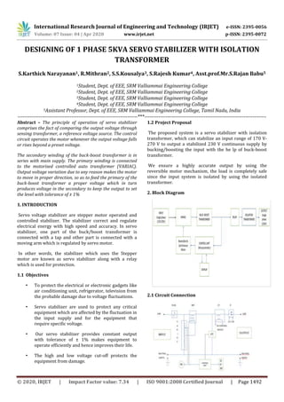
- 1. International Research Journal of Engineering and Technology (IRJET) e-ISSN: 2395-0056 Volume: 07 Issue: 04 | Apr 2020 www.irjet.net p-ISSN: 2395-0072 © 2020, IRJET | Impact Factor value: 7.34 | ISO 9001:2008 Certified Journal | Page 1492 DESIGNING OF 1 PHASE 5KVA SERVO STABILIZER WITH ISOLATION TRANSFORMER S.Karthick Narayanan1, R.Mithran2, S.S.Kousalya3, S.Rajesh Kumar4, Asst.prof.Mr.S.Rajan Babu5 1Student, Dept. of EEE, SRM Valliammai Engineering College 2Student, Dept. of EEE, SRM Valliammai Engineering College 3Student, Dept. of EEE, SRM Valliammai Engineering College 4Student, Dept. of EEE, SRM Valliammai Engineering College 5Assistant Professor, Dept. of EEE, SRM Valliammai Engineering College, Tamil Nadu, India ---------------------------------------------------------------------***---------------------------------------------------------------------- Abstract – The principle of operation of servo stabilizer comprises the fact of comparing the output voltage through sensing transformer, a reference voltage source. The control circuit operates the motor whenever the output voltage falls or rises beyond a preset voltage. The secondary winding of the buck-boost transformer is in series with main supply. The primary winding is connected to the motorised controlled auto transformer (VARIAC). Output voltage variation due to any reason makes the motor to move in proper direction, so as to feed the primary of the buck-boost transformer a proper voltage which in turn produces voltage in the secondary to keep the output to set the level with tolerance of ± 1% 1. INTRODUCTION Servo voltage stabilizer are stepper motor operated and controlled stabilizer. The stabilizer correct and regulate electrical energy with high speed and accuracy. In servo stabilizer, one part of the buck/boost transformer is connected with a tap and other part is connected with a moving arm which is regulated by servo motor. In other words, the stabilizer which uses the Stepper motor are known as servo stabilizer along with a relay which is used for protection. 1.1 Objectives • To protect the electrical or electronic gadgets like air conditioning unit, refrigerator, television from the probable damage due to voltage fluctuations. • Servo stabilizer are used to protect any critical equipment which are affected by the fluctuation in the input supply and for the equipment that require specific voltage. • Our servo stabilizer provides constant output with tolerance of ± 1% makes equipment to operate efficiently and hence improves their life. • The high and low voltage cut-off protects the equipment from damage. 1.2 Project Proposal The proposed system is a servo stabilizer with isolation transformer, which can stabilize an input range of 170 V- 270 V to output a stabilized 230 V continuous supply by bucking/boosting the input with the he lp of buck-boost transformer. We ensure a highly accurate output by using the reversible motor mechanism, the load is completely safe since the input system is isolated by using the isolated transformer. 2. Block Diagram 2.1 Circuit Connection
- 2. International Research Journal of Engineering and Technology (IRJET) e-ISSN: 2395-0056 Volume: 07 Issue: 04 | Apr 2020 www.irjet.net p-ISSN: 2395-0072 © 2020, IRJET | Impact Factor value: 7.34 | ISO 9001:2008 Certified Journal | Page 1493 The secondary of the buck boost transformer is connected in series with the line, The windings(turns ratio) of the variance is controlled by reversible AC synchronous motor, this further controls the primary of the buck boost transformer to proceed with the buck/boost operation respectively. The input to the motor is given by the microcontroller with the help of reference voltage inputed by the user as per requirement. The display is used to show the input voltage and the reference voltage given by the user as per requirement. The isolated transformers connected In between the stabilizer system and the load to reduce the risks. 3. PRINCIPLE OPERATION The principle of operation of servo stabilizer comprises comparing the output voltage through sensing transformer, a reference voltage source. The control circuit operates the motor whenever the output voltage falls or rises beyond a preset voltage. Voltage received from main at input of servo stabilizer is continuously sensed by accessories circuitry and gives feedback to Main control circuitry which consists of Microprocessor. This microprocessor continuously receives values of input voltages. Whenever there is high or low voltage at input of servo stabilizer, the microprocessor gives trigger to motor driver. The secondary winding of the buck-boost transformer is in series with main supply. The primary winding is connected to the motorised controlled autotransformer(VARIAC). Output voltage variation due to any reason makes the motor to move in proper direction, so as to feed the primary of the buck-boost transformer a proper voltage which in turn produces voltage in the secondary to keep the output to set the level with tolerance of ± 1%Based on amount of high voltage or low voltage observed at input, “motor driver” moves servo motor across winding of autotransformer so as to increase of decrease no of winding and hence voltage across primary of buck boost transformer. It is since Servo motor shaft is connected to primary of buck boost transfer. And hence when there is change in voltage across primary of buck boost transfer then induce voltage across its secondary also changes. The motor moves in such a way that proper voltage should be observe across primary of Buck Boost transformer so that voltage across secondary should be equal to set or desired output voltage of servo stabilizer. And voltage across secondary of Buck Boost transformer is output voltage of stabilizer. 3.1 ISOLATION TRANSFORMER Isolation transformer is designed to provide electrical isolation without stepping voltage and current either up or down. It decouples the two circuits and prevents passage of line voltage transient, spikes and galvanic leakages from reaching the sensitive or critical equipment like computers and its peripherals, medical instruments and digital communication & telemetry systems etc. It is used to protect against electric shock, to suppress electrical noise in sensitive devices, or to transfer power between two circuits which must not be connected together. 3.2 Buck/Boost Transformer Buck/Boost transformer connected between mains input and out of stablizer of load terminals. One terminal of primary of buck boost transformer permanently connected to fixed tapping of autotransformer while another end connect to motor shaft. 3.3 Auto transformer It has toroidal shape and auto transformer connected between neutral point and phase of input power supply. 3.4 Motor One end of Primary of Buck Boost transformer connected to shaft of this motor with arm and brush mechanism. When motor moves then this arm shaft moves across winding of autotransformer to increase or decrease number of winding. Motor is generally AC Synchronous motor or DC servo motor which is connected and it is fitted on top of autotransformers centre point. 3.5 CONTROL UNIT It is purely electronic circuitry which controls movement of motor. It consisting of PCBs consisting of solid state circuitry made up of capacitor, register, transistor Amplifier, microprocessor and ICs. Control Circuitry PCB boards needs constant DC power supply. Control circuitry Power supply make available power for PCB boards. It consists of Rectifier (to convert AC to DC) and step down transformer. 4. RESULTS Higher current produces higher losses in electrical motors which causes premature failure of winding. These higher losses of electric motors also increase the losses of cables, switches, transformers and other associated equipment. For smooth continuous operation of motors, over load relays are usually set at 20% higher setting.
- 3. International Research Journal of Engineering and Technology (IRJET) e-ISSN: 2395-0056 Volume: 07 Issue: 04 | Apr 2020 www.irjet.net p-ISSN: 2395-0072 © 2020, IRJET | Impact Factor value: 7.34 | ISO 9001:2008 Certified Journal | Page 1494 5. CONCLUSION The implementation of this project is to increase the lifetime and also the efficiency of the equipment and the appliances used as load .Thus the amount of high voltage or low voltage observed at input, ‘motor driver’ moves servo motor across winding of autotransformer (VARIAC) so as to increase or decrease the number of winding and hence voltage across primary of buck-boost transformer. REFERENCES • https://www.vertexpower.in/about-us.html • Mohammad Shah Alamgir and Sumit Dev, “Design and Implementation of an Automatic Voltage Regulator with great Precision and Proper Hysteresis”, International Journal of Advance Science and Technology, Vol. 75(2015). • https://university.listenlights.com/2017/08/10/ variac-transformer/ • Design of Transformers by Indrajit Dasgupta • Design of electrical machines by AK SHAWNEY • https://ieeexplore.ieee.org/document/5328310 • Naveen Kumar, “Design of a Low Cost Servo Controlled Voltage Stabilizer”, International Journal of Research in Engineering and Technology, 3rd March 2016. • Swati N. Gajera, “Servo voltage stabilizer with Isolation Transformer”, International Journal of Engineering science and computing, March 2017.