IRJET- Analysis of Overhead Water Tank with Different Staging Height and Base Width
•
2 likes•92 views

https://www.irjet.net/archives/V5/i6/IRJET-V5I697.pdf

Recommended
Recommended
More Related Content
What's hot
What's hot (18)
Similar to IRJET- Analysis of Overhead Water Tank with Different Staging Height and Base Width
Similar to IRJET- Analysis of Overhead Water Tank with Different Staging Height and Base Width (20)
More from IRJET Journal
More from IRJET Journal (20)
Recently uploaded
Recently uploaded (20)
IRJET- Analysis of Overhead Water Tank with Different Staging Height and Base Width
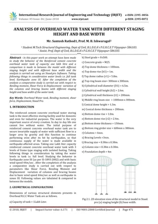
- 1. International Research Journal of Engineering and Technology (IRJET) e-ISSN: 2395 -0056 Volume: 05 Issue: 06 | June-2018 www.irjet.net p-ISSN: 2395-0072 © 2018, IRJET | Impact Factor value: 6.171 | ISO 9001:2008 Certified Journal | Page 471 ANALYSIS OF OVERHEAD WATER TANK WITH DIFFERENT STAGING HEIGHT AND BASE WIDTH Mr. Santosh Rathod1, Prof. M. B. Ishwaragol2 1 Student M.Tech Structural Engineering, Dept of Civil, B.L.D.E.A’s P.G.H.C.E.T Vijayapur-586103. 2 Assist. Prof, Dept of Civil, B.L.D.E.A’s P.G.H.C.E.T Vijayapur-586103. ---------------------------------------------------------------------***--------------------------------------------------------------------- Abstract - In this paper work an attempt have been made to study the behavior of the Reinforced cement concrete overhead water tank of capacity one lakh litre and a comparison is made in between the model with different staging height and with different base width and the analysis is carried out using an Staad.pro Software. Taking following things in consideration water levels i.e. full tank level, Earthquake zone III. After the completion of the analysis a comparative study is carried out with respect to Bending moment, Shear Force & Displacement variation of the columns and bracing beams with different staging height and base width of the water tank. Key Words: Overhead Water tank, Bending moment, shear force, Displacement, Staad Pro. 1. INTRODUCTION The reinforced cement concrete overhead water storing tank is the most effective storing facility used for domestic and even for industrial purposes. The water is the very important source of every creation. In day to day life one cannot live without water. The initial purpose of reinforced cement concrete overhead water tank are to secure invariable supply of water with sufficient flow to a larger area by gravity and this function to continue performing even after its hit by earthquakes, so that continuous supply of the water is made available in earthquake-affected areas. Taking one Lakh liter capacity reinforced cement concrete overhead water tank with 3 levels of frame type staging with isolated footing. Taking following things in consideration by taking the water levels in tank i.e. full level. Studying the behavior in Earthquake zone III (as per IS-1893-2002) and with basic wind speed 44m/sec . After the completion of the analysis a comparative study is carried out with respect to parameters like Shear Force, Bending Moment and Displacement variation of columns and bracing beams due to basic wind speed 44m/sec as well as earthquake in zones III. Following values are tabulated & compared in between the models. 2. GEOMETRICAL CONFIGURATIONS Dimensions of various structural elements presents in Overhead R.C.C Water Tank are as follows. a) Capacity of tank = 1Lakh Liter. b) Steel grade = Fe500. c) Concrete grade = M25. d) Top dome thickness = 100mm. e) Top dome rise (h1) = 1m. f) Top dome radius (r1) = 5.8m. g) Top ring beam size= 300mm x 300mm. h) Cylindrical wall diameter (D1) = 6.5m. i) Cylindrical wall height (h2) = 2.6m. j) Cylindrical wall thickness (t1) = 200mm. k) Middle ring beam size = 1000mm x 300mm. l) Conical dome height = 1.3m. m) Conical dome thickness = 200mm. n) Bottom dome rise = 1.0m. o) Bottom dome rise (r2) = 2.4m. p) Bottom dome thickness = 150mm. q) Bottom ring girder size = 600mm x 380mm. r) Columns = 6nos. s) Bracing Levels =3nos. t) Bracing size = 0.38m x 0.38m. u) Column size = 0.38m x 0.38m. v) Foundation depth = 4m Fig 2.1. 2D elevation view of the structural model in Staad. pro (a) staging height (b) base width.
- 2. International Research Journal of Engineering and Technology (IRJET) e-ISSN: 2395 -0056 Volume: 05 Issue: 06 | June-2018 www.irjet.net p-ISSN: 2395-0072 © 2018, IRJET | Impact Factor value: 6.171 | ISO 9001:2008 Certified Journal | Page 472 3. LOAD CONSIDERATION a) Dead Load: Self weight of all the structural elements. b) Live Load: 1.5KN/m2 on the top dome for maintainace. c) Wind Load: Wind load in terms of wind pressure depend on the Basic wind speed. Tank location: Vijayapur, Karnataka, INDIA, with basic wind speed (Vb=44.0m/sec.) and Design wind pressure (Vd =716.636N/mm2) for comparison of Shear force & bending moment of columns. (as per IS: 875: Part-3). d) Earthquake load: Tank location: Vijayapur, Karnataka, INDIA, With Z=III, R=4.0, I=1.5, Soil Type=Hard soil, Structure Type=R.C.C cylindrical tank at top & a framed staging in bottom. Damping Ratio=5%, Response reduction=SMRF(5),Importancefactor=1.5.For comparison of Shear force & bending moment of columns. (as per IS: 1893:2002). 4. STAAD.PRO MODEL The Tank is modeled for different staging height and base width & the staging part consists of 6columns (0.38x0.38m) & 12bracing beams (0.38x0.38m). The upper cylindrical part having 3 beams bottom circular ring girder (0.38x06.m), bottom ring beam (0.5x1.0m) & top ring beam (0.3x0.3m). Else all part to be consider as a plate of thickness (0.2m) for cylindrical & conical walls. For top & bottom dome respective thickness is taken (0.1m & 0.15m). Fig4.1: 3D view of model Fig 4.2: 2D view of model with different staging height & full water level. Fig 4.3: 2D view of model with different base width & full water level. 5. ASSIGNMENT OF LOAD ON MODEL Dead load of all structural elements taken, Live load as it act on only top dome (1.5KN/m2) for maintainance, Water Loads acting from inside to outside of the model on cylindrical wall & conical slab & bottom dome. Wind pressure is converted into joint load and the values are calculated, the joint load is applied by selecting each panel joint and assigning the respective joint load in X+ and Z+ direction. Wind load calculated as per IS: 875: Part-3. Earth quake loads calculated as per IS: 1893: 2002 & assigning the respective joint load in X+ and Z+ direction Load Combinations are as per IS: 1893: part-2 codal provisions for liquid storage structures. 6. ANALYSIS In this analysis the various loads such as vertical loads which includes weight of tank structure, fittings, and lateral loads like wind and earthquake loads Static analysis has been done for the water tank by considering Earth quake Zone III, damping ratio 5%. The wind loads are calculated using IS 875(part3) & earthquake using IS 1893-2002. The tank is modeled using parameter such as different staging height, different base width for zone III earthquake & wind as X+ and Z+. 7. DISCUSSIONS AND RESULTS The parameters of this study are Shear force, Bending Moment and displacement of columns, bracing beam displacement due to lateral forces like earthquake & wind, on the tank (container & staging part) & comparing the results in between the model kept on leveled ground surface.
- 3. International Research Journal of Engineering and Technology (IRJET) e-ISSN: 2395 -0056 Volume: 05 Issue: 06 | June-2018 www.irjet.net p-ISSN: 2395-0072 © 2018, IRJET | Impact Factor value: 6.171 | ISO 9001:2008 Certified Journal | Page 473 7.1. Bending moment Chart -7.1.1: bending moment values plotted vs. staging height. From the above chart it can be clearly seen that the changes in the bending moment values is found to be going on increasing as we keep on increasing the staging height of the full tank level of 6.5m base width. 7.2. Shear force Chart-7.2.1: Shear force values plotted vs. Staging height. From the above chart it can be clearly seen that the changes in the shear values is found to be going on increasing as we keep on increasing the staging height of the full tank level of 6.5m base width. 7.3. Displacement Chart-7.3.1:displacement values plotted vs. staging height. From the above chart it can be clearly seen that the changes in the max displacement values is found to be going on increasing as we keep on increasing the staging height of the full tank level of 6.5m base width. 7.4. Bending moment Chart-7.4.1: bending moment values plotted vs base width. From the above chart it can be clearly seen that the changes in the bending moment is found to be going on increasing drastically as we keep on increasing the base width of the full tank level of 10.5m staging height.
- 4. International Research Journal of Engineering and Technology (IRJET) e-ISSN: 2395 -0056 Volume: 05 Issue: 06 | June-2018 www.irjet.net p-ISSN: 2395-0072 © 2018, IRJET | Impact Factor value: 6.171 | ISO 9001:2008 Certified Journal | Page 474 7.5. Shear force Chart-7.5.1: shear force values plotted vs. base width. From the above chart it can be clearly seen that the changes in the shear is found to be going on increasing drastically as we keep on increasing the base width of the full tank level of 10.5m staging height. 7.6. Displacement Chart-7.6.1: displacement values plotted vs base width From the above chart it can be clearly seen that the changes in the Max displacement is found to be going on increasing drastically as we keep on increasing the base width of the full tank level of 10.5m staging height. 8. CONCLUSION The conclusions from the analysis results are as follows, 1)Bending moment value has slightly increased due to increase in staging height and the bending moment is increased by 2.9%, 3.1% respectively due to the wind load on the water tank. 2)It is observed that as the height of cylindrical wall reduces and base width increases the value of bending moment drastically increased 32.0% and 38.8%. 3)The base shear value has slightly increased due to increase in staging height and the base shear is increased by 3.3%, 3.6% respectively. 4)It is observed that as the height of cylindrical wall reduces and base width increases the value of base shear drastically increased 45.0% and 47.0%. 5)The displacement value has drastically increased due to reduced height of cylindrical wall and increase in base width, the displacement is increased by 39.38% and 46.4% respectively. REFERENCES 1. Rajkumar, Shivaraj.Mangalgi, Response spectrum analysis of elevated circular and intze water tank. International Research Journal of Engineering Technology IRJET, october 2017. 2. Dr. S.A.Halkude, A.A.Perampalli, Analysis of Water Tank on Sloping Ground, International Journal of Engineering and Innovative Technology (IJEIT), November 2013. 3. A comparative analysis of RCC elevated water tank on sloping and leveled ground by Mr Sunilkumar Hiremath and Prof. S A Warad, IRJET , Aug:2017. 4. IS 1893:2002 Indian standard code for earthquake resistant design of structures, Bureau of Indian standards, New Delhi. 5. Design of reinforced concrete structures by N. Krishna Raju, Third edition 2003 6. IS 3370 (PartIII):1967 Indian standard code of practice for concrete structures for the storage of liquids, Bureau of Indian standards, New Delhi.