A Comparative Analysis of R.C.C Elevated Water Tank on Sloping & Leveled Ground
•
0 likes•101 views

https://www.irjet.net/archives/V4/i8/IRJET-V4I8191.pdf

Recommended
Recommended
More Related Content
What's hot
What's hot (20)
Similar to A Comparative Analysis of R.C.C Elevated Water Tank on Sloping & Leveled Ground
Similar to A Comparative Analysis of R.C.C Elevated Water Tank on Sloping & Leveled Ground (20)
More from IRJET Journal
More from IRJET Journal (20)
Recently uploaded
Recently uploaded (20)
A Comparative Analysis of R.C.C Elevated Water Tank on Sloping & Leveled Ground
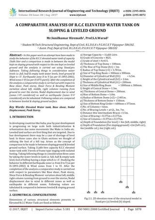
- 1. International Research Journal of Engineering and Technology (IRJET) e-ISSN: 2395-0056 Volume: 04 Issue: 08 | Aug -2017 www.irjet.net p-ISSN: 2395-0072 © 2017, IRJET | Impact Factor value: 5.181 | ISO 9001:2008 Certified Journal | Page 1078 A COMPARATIVE ANALYSIS OF R.C.C ELEVATED WATER TANK ON SLOPING & LEVELED GROUND Mr.Sunilkumar Hiremath1, Prof.S.A.Warad2 1 Student M.Tech Structural Engineering, Dept of Civil, B.L.D.E.A’s P.G.H.C.E.T Vijayapur-586102. 2 Assist. Prof, Dept of Civil, B.L.D.E.A’s P.G.H.C.E.T Vijayapur-586102 ---------------------------------------------------------------------***--------------------------------------------------------------------- Abstract -In this paper work anattempthavebeen madeto study the behavior of the R.C.C elevated water tankofcapacity 1lakh liter and a comparison is made in between the model kept on sloping ground with respect to the one kept on leveled ground and the analysis is carried out using Staad.pro Software. Taking following things in consideration water levels i.e. full, half & empty tank water levels, level ground & Slope is >3’. Earthquake zone II to V (as per IS-1893-2002), Wind zones I-VI (as per IS-875-part3). After the completion of the analysis a comparative study is carried out with respectto Base shear, Peak storey, Shear Force & Bending Moment variation about left, middle, right columns running from ground to over the stories, Nodal displacement due to wind (zones I-VI considered) as well as earthquake (zones II-V considered) are be tabulated. Following values are compared in between leveled & sloping ground surface. Key Words: Elevated Water tank, Base shear, Nodal Displacement, Peak Storey. 1. INTRODUCTION In developing countries like India, year byyeardevelopment is progressing on large scale both industrialization & urbanization due some movements like Make in India etc. Leveled land surface are first thing that are targeted. Due to hue development there may be a case of shortage of level land. In those cases also in Ghats sections we thought of utilizing the foot of a hill top. Arises us the concept of comparison to be made in between slopingground&leveled ground surface. Taking 1Lakh litre capacity R.C.C elevated water tank with 3 levels of frame type staging with isolated footing. Taking following things in considerationthreecases by taking the water levels in tank i.e. full, half & empty tank level, foot of hilltop having a slope which is >3’. Studying the behavior In different Earthquake zone i.e.fromIItoV(asper IS-1893-2002) & Wind zones from I to VI. After the completion of the analysis a comparativestudyiscarriedout with respect to parameters like Base shear, Peak storey, Shear Force & Bending Moment variation about left,middle, right column running from ground to over the stories,Nodal displacement due to wind in different zones as well as earthquake in different zones. Following values are tabulated & compared in between leveled & sloping ground surface. 2. GEOMETRICAL CONFIGURATIONS Dimensions of various structural elements presents in Elevated R.C.C Water Tank are fixed as follows. a) Storage Capacity = 1Lakh Litre. b) Grade of Concrete = M25. c) Grade of steel = Fe415. d) Thickness of Top Dome = 100mm. e) The Rise of Top Dome (h1) = 1m. f) Radius of Top Dome (r1) = 5.781m. g) Size of Top Ring Beam = 300mm x 300mm. h) Diameter of Cylindrical Wall (D1) = 6.5m. i) Height of the Cylindrical wall (h2) = 2.6m. j) Thickness of Cylindrical Wall (t1) = 200mm. k) Size of Middle Ring Beam = 1000mm x 300mm. l) Height of Conical Dome = 1.3m. m) Thickness of Conical Dome = 200mm. n) Rise of Bottom Dome = 1.0m. o) Radius of Bottom Dome (r2) = 2.401m. p) Thickness of Bottom Dome = 150mm. q) Size of Bottom Ring Girder = 600mm x 375mm. r) No. of Columns = 6nos. s) No. of Bracing Levels = at GL, 3m, 7m. t) Distance btw intermediate Braces =3.5m. u) Size of Bracing = 0.375m x 0.375m. v) Size of Columns = 0.375m x 0.375m. w) Depth of Foundation (for level) = 4m (left, middle, right) x) Depth of Foundation (For sloping ground) =2m (left col.), 4m (middle col.), 6m (right col.). Fig 2.1. 2D elevation view of the structural model in Staad.pro (a) leveled (b) sloped.
- 2. International Research Journal of Engineering and Technology (IRJET) e-ISSN: 2395-0056 Volume: 04 Issue: 08 | Aug -2017 www.irjet.net p-ISSN: 2395-0072 © 2017, IRJET | Impact Factor value: 5.181 | ISO 9001:2008 Certified Journal | Page 1079 3. LOAD CONSIDERATION a) Dead Load: Self weight of all the structural elements. b) Live Load: 1.5KN/m2 on the top dome for maintainace. c) Wind Load: Wind load in terms of wind pressure depend on the Basic wind speed. Tank location: Vijayapur, Karnataka, INDIA, with basic wind speed (Vb=44.0m/sec.) and Design wind pressure (Vd =716.636N/mm2) for comparison of Shear force & bending moment of columns. For other parameters changing zone I –VI (as per IS: 875: Part-3). d) Earthquake load: Tank location: Vijayapur, Karnataka, INDIA, With Z=III, R=4.0, I=1.5, Soil Type=Hard soil, Structure Type=R.C.C cylindrical tank at top & a framed staging in bottom. Damping Ratio=5%, Response reduction=SMRF(5),Importancefactor=1.5.For comparison of Shear force & bending moment of columns. For other parameters changing for zone II –V (as per IS: 1893:2002). 4. STAAD.PRO MODEL The Tank is modeled using two mass system, & the staging part consists of 6columns (0.375x0.375m) & 12braces (0.375x0.375m). The upper cylindrical part having 3 beams bot. circular ring girder (0.375x06.m), bot. ring beam (0.5x1.0m) & top ring beam (0.3x0.3m). Else all part to be consider as a plate of thickness (0.2m) for cylindrical & conical walls. For top & bot. dome respective thickness is taken (0.1m & 0.15m). Fig4.1: 3D view of model Fig 4.2: 2D view of model with full, half, empty water level. Fig 4.3: 2D view of model with full, half, empty water level. Dead load of all structural elements taken, Live load as it act on only top dome (1.5KN/m2) for maintainace, Water Loads acting from inside to outside of the model on cylindrical wall & conical slab & bottom dome. Wind pressure is converted into joint load and the values are calculated, the joint load is applied by selecting each panel joint and assigning the respective joint load in X+ and Z+ direction. Wind load calculated as per IS: 875:Part-3. Earth quake loads calculated as per IS: 1893:2002 & assigning the respective joint load in X+ and Z+ direction Load Combinations are as per IS: 1893: part-2 codal provisions for liquid structures. 6. ANALYSIS In this analysis the various loadssuchasvertical loadswhich includes weight of tank structure, fittings, and lateral loads like wind and earthquake loadsStaticanalysishasbeendone for the tower by considering Earth quake Zone II-V, damping ratio 5%. The wind loads are calculated using IS 875(part3)& earthquake using IS 1893-2002. The tank is modeled using parameter such as constant height, constant base width, and then varying thezonesofearthquake& wind as X+ and Z+. 7. DISCUSSIONS AND RESULTS The parameters of this study are Base shear, Peak Storey, Shear force & Bending Moment on columns, Nodal Displacement due to lateral forces like earthquake & wind, on the tank (container & staging part) & comparing the results in between the model kept on sloping & leveled ground surface. 7.1. Base Shear 5. ASSIGNMENT OF LOAD ON MODEL
- 3. International Research Journal of Engineering and Technology (IRJET) e-ISSN: 2395-0056 Volume: 04 Issue: 08 | Aug -2017 www.irjet.net p-ISSN: 2395-0072 © 2017, IRJET | Impact Factor value: 5.181 | ISO 9001:2008 Certified Journal | Page 1080 Chart -1: base shear values plotted vs. earthquake zones. 1) From the plotted graph is can be clearly seen that the changes in the base shear found to be going on increasing as we keep on increasing zone factor i.e from zone-II to zone – V. 2) In the model that’s on the level ground surface, from the graph it is seen as the graph seen increasing from zone-II to zone-V, for all the case i.e Full tank, Half tank, empty tank levels. 3) In the model that’s on the sloping ground surface, from the graph it is seen increasing in the cases of full tank level. 4) In the model that’s on the sloping ground surface, from the graph .In the case of empty tank up to zone-IV its increase then remain same for zone-IV. 5) In the model that’s on the sloping ground surface, from the graph .In the case of half tank from zone-II to zone –III decreases than increases to zone-IV then decreases in zone- v. 7.2. Peak Storey Shear Chart-2: Peak Storey shear values plotted vs. earthquake zones . 1) From the graph is can be seen that as the go on increasing order of the zones of earthquake the peak storey shear too increases for all the cases. 2) It can be seen that the peak storey shear for one zone, like say zone-III, you can see that, it is less empty tank are comparatively more in full tank. 3) The peak storey shear is for model kept on level & sloped when compared found that it is less in case of sloped ground then in level ground for a particular zone & particularcaseis taken in consideration. 7.3. Shear Force Chart-3: shear values.
- 4. International Research Journal of Engineering and Technology (IRJET) e-ISSN: 2395-0056 Volume: 04 Issue: 08 | Aug -2017 www.irjet.net p-ISSN: 2395-0072 © 2017, IRJET | Impact Factor value: 5.181 | ISO 9001:2008 Certified Journal | Page 1081 1) We can see from the graph that in the level surface model, as we move from right to left column the values of left & right column remain same, starting from ground to last storey height. 2) In the sloped surface model, the picture is little different, as we move from right to left column (from lower side to higher side of sloping ground), the valvesgoesonincreasing, especially below ground which is 70% . 3) In level ground the middle column is have more shear force compared to left and right columns,around 20% to 30% as we come from higher to lower storey. 4) In sloping ground surface the middle column has shear little higher then right column which is around 15% to 25% as we come from higher storey to lower storey. 7.4. Bending moment Chart-4: shear values. 1) When we observe the graph plotted by obtained data for the leveled surface for the left & right column it is same. 2) In the sloping ground we find an increase in the bending moment as we move from right columntoleftcolumn(lower level to higher level on the sloping ground), significantly seen for the below ground level which is around 30% more. 3) Here we can also see that the bending movement is seen more in middle column (except the below GL), as compared to left & right columns. 4) The bending moment found to decreases as we keep moving above ground level. 7.5. Nodal displacement due to Seismic Forces Chart-5: shear values. 1) The maximum displacement of the node present in the model usually occurs at the topmost node. 2) From the graph it is seen that as the displacement for the node go on increasing for all cases of both the sloped & leveled goes increasing with earthquake zones. 3) In the cases of leveled ground surface seen that for half tank case for zone 2 is 25% then remaining displacement in other zones. 4) In case of half tank on leveled ground for zone 2 is5%less than the remaining zones. 5) In both the cases we fine the displacement is more for the full tank cases. 6) In the sloped ground for the half tank case for zone 5 we can see relatively more displacement compared to its own differences in between zones. 7.6. Nodal Displacement due to Wind Forces
- 5. International Research Journal of Engineering and Technology (IRJET) e-ISSN: 2395-0056 Volume: 04 Issue: 08 | Aug -2017 www.irjet.net p-ISSN: 2395-0072 © 2017, IRJET | Impact Factor value: 5.181 | ISO 9001:2008 Certified Journal | Page 1082 Chart-6: shear values 1) We found the maximum displacement of a node is usually seen at the topmost point of the model. 2) From the graph it is seen the nodal displacement is found maximum for the full tank case for both the model kept on the level & sloped surface. 3) It is also seen that the nodal displacement due wind force is found almost same for the case half & empty tank for both the model one kept on level & other on sloped. 4) The nodal displacement in the full is found % more than the other two cases. 8. CONCLUSION 1) Designing of elevated water tank is very much tedious more on putting it on a sloping ground is risky. 2) For the sloping ground we saw that from our analysis for the parameter like shear force for all the cases in all the zones we found it was steeply rising to higher value as we move from column resting on lower side to column resting on higher side on a sloping surface. 3) For the sloping ground we saw that from our analysis for the parameter like bending moment for all the cases in all the zones we found it was also steeply rising to higher value as we move from column resting on lower side to column resting on higher side on a sloping surface. 4) On moving above the ground thatmeansonestoreyabove the other the parameter shear force and bending moment start to become milder & milder. 5) In all these cases we also found that there was not significantly change in axial force acting in model over the slope ground compared to level ground surface. 6) When we start comparing the base shear for all the cases on both surface with different seismic zones, we found increasing with respect to rise in zones. 7) The base shear valves on both the surface in the full tank & half tank cases the difference is less (approx. 10%). 8) The base shear valves on both the surface in the half & empty tank cases the difference is more, its due to sloshing effect of water. 9) Nodal Displacement due to earthquake & wind we have considered the topmost node in the model, as we know displacement is max. at top. 10) Nodal Displacement due to earthquake & wind we have the displacement in Y & Z axis remained same for all the cases in level surface, similarly was seen in sloping ground too. 11) Nodal Displacement due to earthquake & wind we observe that in level ground displacement in Z direction on level ground remain same or zero , but in sloping surface there was little seen for all the three cases. 12) Nodal Displacement due to earthquake & wind we observe that for both cases the displacement is found more in case of full tank. 13) Nodal Displacement due to & wind we had same values for half & empty tank on both surface. REFERENCES 1) Design Analysis &ComparsionOfIntzeType WaterTank For Different Wind Speed And Seismic As Per Indian Codes. By: Nitesh.J.Singh&Mohd.Ishtiyaque. 2) Analysis Of Water Tank On Sloping Ground By: Dr.S.A.Halkude, And A.A.Perampalli. 3) Seismic Performance Of Circular Elevated Water Tank Author :Rupachandra.J.Aware, Dr.Vageesha.S.Mathada. 4) Structural Assessment OfCircularOverheadWaterTank Based On Frame Staging Subjected To Seismic Loading By S.K.Jangave, Dr.P.B.Murnal. 5) Seismic Analysis Of Rc Elecvated Water Tank By Pradnya.V.Sambary&7 D.M.Joshi. BIOGRAPHIES Sunilkumar Hiremath Student, M.Tech. Structures. B.L.D.E.A’s P.G.H.C.E.T Vijayapura. Prof.S.A.Warad, Assist. Prof Structural Engg. Dept of Civil engg. B.L.D.E.A’s P.G.H.C.E.T Vijayapura.