DIRECTIONAL AUDIO (Ultrasonic Directive Speaker)
•
0 likes•6 views

https://www.irjet.net/archives/V9/i6/IRJET-V9I6636.pdf

Recommended
Recommended
More Related Content
Similar to DIRECTIONAL AUDIO (Ultrasonic Directive Speaker)
Similar to DIRECTIONAL AUDIO (Ultrasonic Directive Speaker) (20)
More from IRJET Journal
More from IRJET Journal (20)
Recently uploaded
Recently uploaded (20)
DIRECTIONAL AUDIO (Ultrasonic Directive Speaker)
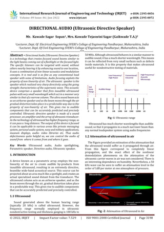
- 1. © 2022, IRJET | Impact Factor value: 7.529 | ISO 9001:2008 Certified Journal | Page 3198 DIRECTIONAL AUDIO (Ultrasonic Directive Speaker) Mr. Kawade Sagar Sopan1, Mrs. Kawade Tejaswini Sagar (Gaikwade T.A.)2 1Lecturer, Dept. Of Electrical Engineering SVERI’s College of Engineering Pandharpur, Maharashtra, India 2Lecturer, Dept. Of Civil Engineering SVERI’s College of Engineering Pandharpur, Maharashtra, India ---------------------------------------------------------------------***--------------------------------------------------------------------- Abstract –DirectionalAudio(UltrasonicDirectiveSpeaker) is a technology that creates focused sound beams similar to the light beams coming out of a flashlight or the focused light. The specific listeners can be targeted with sound, without others nearby hearing it by enhancing sound to one location,. It uses a combination of non-linear acoustics and modulation concepts. It is real and is as fine as any conventional loud speaker with some of limitations. Audio focusing exploits the property of non-linearity of air. The ultrasonic speaker is the speaker which realized very sharp directivity using the going straight characteristics of the supersonic wave. This acoustic device comprises a speaker that fires inaudible ultrasound pulses with very small wavelength which act in a manner very similar to that of a narrow column. The ultra sound beamacts as an airborne speaker and as the beam movesthroughtheair gradual distortion takes place in a predictable way due to the property of non-linearity of air. This gives rise to audible components that can be accurately predicted and precisely controlled. Ultrasonic directive speaker is made of a sound processor, an amplifier and the arrayofultrasonic transducer. As the technology of ultrasoundhashigherfrequencyrange, so it can pass a long distance. The output of this device is focused it can be applicable in various areas like private messaging system, personal audio system, navy andmilitaryapplications, museum displays, audio- video libraries etc. Thus audio defectiveness quite helpful as, we can control the audio of sound from where it comes from and where it goes . Key Words: Ultrasound audio, Audio spotlighting, Parametric speaker, Directive audio, Ultrasonic speaker. 1. INTRODUCTION A device known as a parametric array employs the non- linearity of the air to create audible by-products from inaudible ultrasound, resulting in an extremely directive, beamlike wide-band acoustical source. This source can be projected about an area much like a spotlight, andcreates an actual specialized sound distant from the transducer. The ultrasound column acts as an airborne speaker, and as the beam moves through the air, gradual distortion takes place in a predictable way. This gives rise to audible components that can be accurately predicted and precisely controlled. 1.1 Ultrasound Sound generated above the human hearing range (typically 20 kHz) is called ultrasound. However, the frequency range normally employed in ultrasonic nondestructive testing and thickness ganging is 100 kHz to 50 MHz. Although ultrasoundbehaves in a similar manner to audible sound, it hasa much shorter wavelength. Thismeans it can be reflected from very small surfaces such as defects inside materials. It is this property that makes ultrasound useful for nondestructive testing of materials. Fig -1: Ultrasonic range Ultrasound has much shorter wavelengths than audible sound, so that it propagates in a much narrower beam than any normal loudspeaker system using audio frequencies 1.2 Attenuation of ultrasound in air The Figure provided an estimation of the attenuationthat the ultrasound would suffer as it propagated through air. From this figure correspond to completely linear propagation, and the exact effect of the nonlinear demodulation phenomena on the attenuation of the ultrasonic carrier waves in air was not considered. There is an interesting dependence on humidity. Nevertheless, a 50 kHz wave can be seen to suffer an attenuation level in the order of 1dB per meter at one atmosphere of pressure. Fig -2: Attenuation of Ultrasound in Air International Research Journal of Engineering and Technology (IRJET) e-ISSN: 2395-0056 Volume: 09 Issue: 06 | Jun 2022 www.irjet.net p-ISSN: 2395-0072
- 2. International Research Journal of Engineering and Technology (IRJET) e-ISSN: 2395-0056 Volume: 09 Issue: 06 | Jun 2022 www.irjet.net p-ISSN: 2395-0072 © 2022, IRJET | Impact Factor value: 7.529 | ISO 9001:2008 Certified Journal | Page 3199 2. CONCEPTIUAL BACKGROUND 2.1 Ultrasonic nonlinear acoustics The equations that govern nonlinear acoustics are quite complicated and unfortunately they do not have general analytical solutions. They usually require the use of a computer simulation . However, Berktay performed an analysis under some simplifying assumptions that allowed the demodulated Sound Performance Lab to be written in terms of the amplitude modulated ultrasonic carrier wave pressure Pc and various physical parameters. A precompensation scheme can be based from Berktay’s expression, as shown in fallowing equation, by taking the square root of the base band signal envelope E and then integrating twice to inverttheeffectofthedoublepartialtime derivative. The analogue electronic circuit equivalents of a square root function is simply an op-amp with feedback, and an equalizer is analogous toanintegrationfunction.However these topic areas lie outside the scope of this project. p2(x,t) = K ·Pc2 · (∂2/ ∂t2) · E2(x,t) Where, p2(x,t) = Audible secondary pressure wave K = misc. physical parameters Pc2 = SPL of the ultrasonic carrier wave E(x,t) = Envelope function This equation says that the audible demodulated ultrasonic pressure wave (output signal) is proportional to the twice differentiated, squared version of the envelope function (input signal). Precompensation refers to the trick of anticipating these transforms and applying the inverse transforms on the input, hoping that the output isthencloser to the untransformed input. In effect the transducers needed to keep up with what the digital precompensationdemanded known as a broader frequency response. 2.2 Focused Beem of Sound The parametric speaker is the speaker which realized very sharp directivity using the going straight characteristics of the supersonic wave. It is said that the human hearing can hear a sound wave to about around 20kHz, but actually it is known for the frequency that is considerably lower than 20kHz not to hear. It depends on age, but it may be said that around 14kHz are the one that they should hear to the utmost. The element to generate a supersonic wave uses a pressure electric phenomenon to be called piezoelectric element. With the kit, I use a supersonic wave transducer with the peak for 40kHz. Because themountainofthepeak is steep, It cannot let pass the too wide band. A normal human being cannot hear the supersonic wave of 40kHz at all.Some methods to convert a supersonic wave into the sound wave that a human being can hear are devised. The one is a method to reproduce a sound of the frequency equal to the difference of the supersonic wave using two different supersonic waves source of the frequency. For example, a sound of 1 kHz equal to the difference is known as undulation when it gives a supersonic wave of 40kHz and 41kHz. I use a supersonic wave of 40 kHz as a carrier wave, and amplitude modulation is to give an irregular supersonic wave, and the neighborhood where two supersonic waves intersect can generate the sound of the audio domain from the other speaker. Because it is necessary for this method to continue giving a supersonic wave in a case without the signal consistently, an inefficient thing is a fault. 2.3 Sound from ultrasound The Sound from ultrasound is the name given here to the generation of audible sound from modulated ultrasound without using an active receiver. This happens when the modulated ultrasound passes through a nonlinear medium which acts, intentionally or unintentionally, as a demodulator. A transducer can be made to project a narrow beam of modulated ultrasound that ispowerful enough,at100to110 dB SPL, to substantially change the speed of sound in the air that it passes through. The air within the beam behaves nonlinearly and extracts the modulation signal from the ultrasound, resulting in sound that can be heard only along the path of the beam, or that appears to radiate from any surface that the beam strikes. This technologyallowsa beam of sound to be projected over a long distance to be heard only in a small well defined area, a listener outside the beam hears nothing. This effect cannot be achieved with conventional loudspeakers, because sound at audible frequencies cannot be focused into such a narrow beam. There are some limitations withthisapproach.Anythingthat interrupts the beam will prevent the ultrasound from propagating, like interrupting a spotlight’s beam. For this reason, most systems are mounted overhead, like lighting. 2.4 Non linearity of air When inaudible ultrasound pulses are fired into the air, it spontaneously converts the inaudible ultrasound into audible sound tones, hence proved that aswithwater,sound propagation in air is just as non-linear. A parametric array employs the non-linearity of the air to create audible by- products from inaudible ultrasound, resulting in an extremely directive, beamlike wide-band acoustical source. This source can be projected about an area much like a spotlight, and creates an actual specialized sound distant from the transducer. The ultrasound column acts as an airborne speaker, and as the beam moves through the air, gradual distortion takes place in a predictable way. This gives rise to audible components that can be accurately
- 3. International Research Journal of Engineering and Technology (IRJET) e-ISSN: 2395-0056 Volume: 09 Issue: 06 | Jun 2022 www.irjet.net p-ISSN: 2395-0072 © 2022, IRJET | Impact Factor value: 7.529 | ISO 9001:2008 Certified Journal | Page 3200 predicted and precisely controlled. However, the problem with firing of ultrasoundpulses,andhavingtheminterfere to produce audible tones is that the audible components created are nowhere similar tothecomplexsignalsinspeech and music. Human speech, as well as music, contains multiple varying frequency signals, which interfere to produce sound and distortion. Togeneratesuchsoundoutof pure ultrasound tones is not easy. the idea of using pure ultrasound signals as a carrier wave, and superimposing audible speech and music signals on it to create a hybrid wave. If the range of human hearing is expressed as a percentage of shifts from the lowestaudiblefrequencytothe highest, it spans a range of 100,000. No single loudspeaker element can operate efficiently or uniformly over this range of frequencies. In order to deal with this speaker manufacturers carve the audio spectrum into smaller sections. This requires multiple transducers and crossovers to create a ’higher fidelity’ system with current technology. 3 . TECHNOLOGY OVERVIEW 3.1 Voice frequency modulation Diagram showing the overall method, ofhowsilenthypnosis may be transmitted to a target without the target’s being aware. Fig -2: Conceptual Block Diagram Ultrasound is vibration of theair,aliquid,orasolid,above the upper limit of human hearing which is roughly 15 kHz in adults. Voice-Frequency Modulation uses a tone at or near that upper limit, and the speaker’s voice varies thefrequency slightly. Either a tinnituslike soundornothingisheardbythe target. Fig -3: Illustration showing the operation of ”silent sound” with the human hearing system, using near- ultrasound, Voice-Frequency Modulation 3.2 Transducer Array or speaker unit There are several type of ultrasonic transducer around. But the use of 16 mm diameter devices specified for 40 kHz and 28 kHz is sufficient . A minimum array of 50 ultrasonic transducers is required to make an effective speaker unit. If the unit is going to be used in range outdoors thenneedmore than array of 100 ultrasonic transducers. All transducers should be carefully distributed to maintain phase. Ultrasonic transducers are made from piezoelectric ceramic materials. When a voltage isapplied to the device, aspecialtypeoffoilis deformed inside, generating a supersonic sound wave of a specific frequency. Typically, the transducers sound output reaches 105120 dBat 30 cmdistance,whenavoltageof1020 Vrms is applied, corresponding to 2856 Vpp and that raises the question if a similarly high supply voltage is needed. Electrically, an ultrasonic transducer has the properties of a capacitor, which can be madepart of a series resonantcircuit by putting an inductor in series. Tuning the inductortoabout 40 kHz enables the transducer to be drivenfromalowsupply voltage. Fig -3 Array Structure
- 4. International Research Journal of Engineering and Technology (IRJET) e-ISSN: 2395-0056 Volume: 09 Issue: 06 | Jun 2022 www.irjet.net p-ISSN: 2395-0072 © 2022, IRJET | Impact Factor value: 7.529 | ISO 9001:2008 Certified Journal | Page 3201 4 . APPLICATION AREA AND BENEFIT There are two ways to use directional audio, First, it can direct sound at a specific target, creating a contained area of listening space which is called Direct Audio. Second, it can bounce off of a second object, creating an audio image. This audio image gives the illusion of a loudspeaker, which the listener perceives as the source of sound, which is called, projected Audio. This is similar to the way light bounces off of objects. In either case, the sounds source is not the physical device you see, but the invisible ultrasound beam that generates it. Directional audio technology have fallowing benefits over conventional sound speakers. Small and light weight Easy to mount, very thin and flat No Mechanical Vibration or Microphone coupling No magnets or voice coils No cabinets, boxes or housings required No back wave emissions, can be surface mounted Controlled directionality Projected audio can possible Reduce microphone and speaker feedback From such above benefits directional audio has wide range of application area like In personal audio system Audio-video library use In commercial security In military for long range audio transformation The combination of modulation and some of mathematical equations, it is quite beautiful, interesting, helpful technology designed. Directional audio (Ultrasonic Directive Speaker) really put sound where you want it and will be a very helpful feature audio technology. REFERENCES [1] Kazunori Miura (Japan),’Ultrasounic DirectiveSpeaker’, Elektor,032011,PP Page No.56- 59.(http://www.elector.com) [2] ’HolosonicandAudioSpotlight’,Holosonic ResearchLab, Inc., address: Holosonics, 400 Pleasant St., Watwrtown, Ma 02472(http://www.holosonics.com [3] ’The State of Unclassified and Commercial Technology Capable of Some Electronic Mind Control Effects’, Eleanor White, P.Eng. April 4, 2000 (http://www.raven1.net/uncom.htm ..or.. http://www.bestnet.org/ raven1/uncom.htm) AUTHOR Mr. Kawade Sagar Sopan I have been working as a Lecturer of Dept. of Electrical Engineering at SVERI’s college of engineering Pandharpur, Solapur. I had completed my B.E. in Electrical engineering from Solapur University ; MBA Human resource management from YCMOU Nashik. Mrs. Kawade Tejaswini Sagar (Gaikwad T.A.) I have been working as a Lecturer of Dept. of Civil Engineering at SVERI’s college of engineering Pandharpur, Solapur. I had completed my B.E. in Civil engineering from Savitribai Phule Pune University. 5. CONCLUSION