SlideShare a Scribd company logo
1 of 13
.
ULTRASONIC
TESTING
-------------------------------------
This paperexplains about the ultrasonic
testing which uses high frequencysound
energy to conduct examinations and make
measurements. It also illustrate the general
inspection principle and typical inspection
configuration.
ASISH MANI ABRAHAM
SANJU TOM
7/10/2014
ULTRASONIC TESTING
Ultrasonic is a name given to the study and the application of sound waves having frequency higher
than those waves human ear can hear. Ultrasonic sound starts from 20 KHz and above and the testing
frequency ranges from 100 KHz to 25 MHz Ultrasonic examination can be conducted on a wide
variety of materials including casting, forging, weld and composites.
 Infrasonic - Below 16 Hz
 Sonic Sound - 16 Hz to 20000 Hz
 Ultrasonic Sound - Greater than 20 KHz
SOUND WAVE FORMS
1) Compression Waves ( Longitudinal Waves)
 Sound propogation is perpendicular to the specimen and particle movement is parallel
to the sound direction.
 Compression Waves travel through Solid, Liquid and Gases.
 Compression Waves can be generated by normal probe.
 Sound’s propogation speed depends on the type, temperature and composition of the
,medium through which it propagates.
 Velocity of compression wave in steel is 5920 m/s.
2) Shear Waves ( Transverse Waves)
 It is only used in solid substances.
 The wave movement is right angle to the particle vibration.
 Velocity of shear wave in steel is 3250 m/s.
 The particle does not move along with the waves, they simply oscillate up and down
about their individual equilibrium position as the wave passes by.
Difference between Compression wave and shear wave
3) Surface Waves ( Rayleigh Waves)
 It propagates in solid surface.
 It travels through near surface and surface level penetration.
 Propogation of surface wave is elliptical.
 Only surface testing is possible using this wave.
4) Lamb Waves ( Plate Waves)
 Lamb wave is produced by changing of surface waves.
 It have no particular velocity.
 The velocity changes with frequency and plate thickness.
 There are two types of lamb waves: Symmetrical and Asymmetrical.
 They are used to test very thin materials.
COUPLANT
A Couplant is used between transducer phase and the phase of test surface to ensure efficient sound
transmission from transducer to test surface. The presence of air between the transducer and the test
material causes a great difference in acoustic impedance at the interface. A couplant can be any of a
vast variety of liquids , semi-liquids , paste and even some solid that will satisfy the following
requirements.
 A couplant must be easy to apply.
 A couplant must be harmless to the test specimen and transducer.
 A couplant must wet both the surface of the test specimen and face of the transducer
and excludes whole air between them.
SNELL’S LAW
MODE CONVERSION
1. First Critical Angle
The angle of incidence at which the longitudinal wave pass through the surface of the second
medium or perpendicular to the imaginary line is called First Critical Angle.
First Critical Angle = Sin-1 ( Vi/VR)
2. Second Critical Angle
The angle of incidence at which shear wave passes through the surface of the second
medium or perpendicular to the imaginary line is called Second Critical Angle. The refracted
shear wave is called surface wave and the refracted longitudinal wave is called plate wave or
lamb wave.Second Critical Angle = Sin-1(Vi/VR)
ULTRASONIC TESTING EQUIPMENT
Principle
When ultrasonic waves from a piezo-electric crystal are made to propagate in a material through
proper coupling it will be partially reflected or refracted when there is a change in medium or an
interface , say the presence of a discontinuity or the opposite surface of the sound entry. The energy of
the reflected ultrasonic waves depends upon the severity of the defect, the area or the orientation with
respect to the direction of sound entry. The reflected wave is picked by a receiver and amplified for
evaluation.
Major Components of Ultrasonic Testing Equipment.
I. Pulse Generator: It energise the timer and pulser transmitter.
II. Pulse Transmitter: It energise the piezoelectric crystal in short pulses of regular interval .
III. Probes: It generates the longitudinal sound waves and or shear sound waves.
IV. Receiver : It receives the electrical signal and amplify the signals and feed it in to sweep
and marker circuits.
V. Sweep Circuits: The horizontal line or base line of the ultrasonic testing screen is
controlled by sweep circuits. Normally the value of sweep reads from left to right at fixed
points.
VI. Marker Circuits: The amount of refraction in a particular area is displayed in CRT screen
with the help of a marker circuit.
VII. Timer: It is the heart of the equipment. It is the source of all timing signals in the UT
equipment.
PROBES
A probe sends a sound wave in to a test material. There are two indications , one from the initial
pulse of the probe , and the second due to the backwall echo. A defect creates a third indication and
simultaneously reduces the amplitude of the backwall indication.
TYPESOF PROBES
 Normal Probe
 Angular Probe
 T-R Probe
Normal Probes
It is used to inspect thickness and measure flaws on bars, plates, casting, forgings and extrusions.
Structure Of Normal Probe
Calibration of Normal Probe
Calibration Block Used: IIW V1 Block.
Input Values:
Angle =0 degree
Range =100
Velocity =5920 m/s
Mode = T+R
Steps:
 Horizontal Linearity Checking
 Vertical Checking
H1/H2 = H3/H4
 Sensitivity Check
S = Wavelength/2
Wavelength = Velocity/Frequency
=(6000*1000)/(4*1000000)
= 1.5mm
S= 1.5/2 =0.75mm
 Resolution Check
 Amplitude Check
dB = 20 log ( H2 /H1)
 Penetration Check
Set Range=200 and Frequency= 25dB
Angle Probes
In this the echo of a discontinuity on the instrument display does not give us any direct information
about its position in the material. The only available information for determination of the reflector
position is the scale position and therefore the sound path, this means the distance of the discontinuity
from the index point of the probe. The mathematics of the right angled triangle help us to evaluate the
surface distance and the depth of a reflector which are both important for ultrasonic testing.
Calibration of Angle Probe
Calibration Block Used: IIW V2 Block
Input Values:
Angle = 70 degree
Range = 100mm
Velocity = 3250 m/s
Mode = T+R
Steps:
 Horizontal Linearity Checking
 Sensitivity Checking

More Related Content

What's hot

Eddy Current Testing (ECT)- NDT
Eddy Current Testing (ECT)- NDTEddy Current Testing (ECT)- NDT
Eddy Current Testing (ECT)- NDTSukesh O P
 
Presentation on ndt
Presentation on ndtPresentation on ndt
Presentation on ndtniroj yadav
 
Radiographic Testing (RT)- NDT
Radiographic Testing (RT)- NDTRadiographic Testing (RT)- NDT
Radiographic Testing (RT)- NDTSukesh O P
 
Introduction to Liquid Penetrant Testing
Introduction to Liquid Penetrant TestingIntroduction to Liquid Penetrant Testing
Introduction to Liquid Penetrant TestingHareesh K
 
Magnetic Particle Testing
Magnetic Particle Testing Magnetic Particle Testing
Magnetic Particle Testing Mani Vannan M
 
Introduction to NDT and Visual Inspection
Introduction to NDT and Visual Inspection Introduction to NDT and Visual Inspection
Introduction to NDT and Visual Inspection Hareesh K
 
Radiographic testing
Radiographic testingRadiographic testing
Radiographic testingzoha nasir
 
M4 ndt me 367 introductiontoultrasonictesting
M4 ndt me 367 introductiontoultrasonictestingM4 ndt me 367 introductiontoultrasonictesting
M4 ndt me 367 introductiontoultrasonictestingHareesh K
 
Phased Array Ultrasonic Testing in lieu of Radiography
Phased Array Ultrasonic Testing in lieu of RadiographyPhased Array Ultrasonic Testing in lieu of Radiography
Phased Array Ultrasonic Testing in lieu of RadiographyMike Belcher
 

What's hot (20)

Ultrasonic testing
Ultrasonic testingUltrasonic testing
Ultrasonic testing
 
Radiography ndt
Radiography ndtRadiography ndt
Radiography ndt
 
Introduction to Ultrasonic Testing
Introduction to Ultrasonic TestingIntroduction to Ultrasonic Testing
Introduction to Ultrasonic Testing
 
Eddy Current Testing (ECT)- NDT
Eddy Current Testing (ECT)- NDTEddy Current Testing (ECT)- NDT
Eddy Current Testing (ECT)- NDT
 
NON-DESTRUCTIVE TESTING
NON-DESTRUCTIVE TESTINGNON-DESTRUCTIVE TESTING
NON-DESTRUCTIVE TESTING
 
Presentation on ndt
Presentation on ndtPresentation on ndt
Presentation on ndt
 
Paut full notes
Paut  full notesPaut  full notes
Paut full notes
 
Radiographic Testing (RT)- NDT
Radiographic Testing (RT)- NDTRadiographic Testing (RT)- NDT
Radiographic Testing (RT)- NDT
 
5.ULTRASONIC TESTING
5.ULTRASONIC TESTING5.ULTRASONIC TESTING
5.ULTRASONIC TESTING
 
Ndtm 3-eddy current
Ndtm 3-eddy currentNdtm 3-eddy current
Ndtm 3-eddy current
 
ULTRASONIC TESTING REPORT
ULTRASONIC TESTING REPORTULTRASONIC TESTING REPORT
ULTRASONIC TESTING REPORT
 
Introduction to Liquid Penetrant Testing
Introduction to Liquid Penetrant TestingIntroduction to Liquid Penetrant Testing
Introduction to Liquid Penetrant Testing
 
Magnetic Particle Testing
Magnetic Particle Testing Magnetic Particle Testing
Magnetic Particle Testing
 
Magnetic Particle Inspection
Magnetic Particle InspectionMagnetic Particle Inspection
Magnetic Particle Inspection
 
Eddy current testing
Eddy current testingEddy current testing
Eddy current testing
 
Introduction to NDT and Visual Inspection
Introduction to NDT and Visual Inspection Introduction to NDT and Visual Inspection
Introduction to NDT and Visual Inspection
 
Radiographic testing
Radiographic testingRadiographic testing
Radiographic testing
 
M4 ndt me 367 introductiontoultrasonictesting
M4 ndt me 367 introductiontoultrasonictestingM4 ndt me 367 introductiontoultrasonictesting
M4 ndt me 367 introductiontoultrasonictesting
 
Phased Array Ultrasonic Testing in lieu of Radiography
Phased Array Ultrasonic Testing in lieu of RadiographyPhased Array Ultrasonic Testing in lieu of Radiography
Phased Array Ultrasonic Testing in lieu of Radiography
 
Acoustic Emission testing
Acoustic Emission testingAcoustic Emission testing
Acoustic Emission testing
 

Viewers also liked

Viewers also liked (20)

Ultrasonic testing
Ultrasonic testingUltrasonic testing
Ultrasonic testing
 
Ultrasonic testing
Ultrasonic testingUltrasonic testing
Ultrasonic testing
 
Ut P1.Ppt(New)
Ut P1.Ppt(New)Ut P1.Ppt(New)
Ut P1.Ppt(New)
 
Ut procedure general
Ut procedure generalUt procedure general
Ut procedure general
 
Ut P3
Ut P3Ut P3
Ut P3
 
Ut P2
Ut P2Ut P2
Ut P2
 
Ut P4
Ut P4Ut P4
Ut P4
 
Ut P5 (Product Tech.)
Ut P5 (Product Tech.)Ut P5 (Product Tech.)
Ut P5 (Product Tech.)
 
Ultrasonics aws
Ultrasonics awsUltrasonics aws
Ultrasonics aws
 
chapter sound for class 9 ppt
chapter sound for class 9 ppt chapter sound for class 9 ppt
chapter sound for class 9 ppt
 
KINETIC
KINETICKINETIC
KINETIC
 
Non-destructive Testing
Non-destructive TestingNon-destructive Testing
Non-destructive Testing
 
Electromagnetic Field Theory Lecture Notes
Electromagnetic Field Theory Lecture NotesElectromagnetic Field Theory Lecture Notes
Electromagnetic Field Theory Lecture Notes
 
Ultrasonic testing
Ultrasonic testingUltrasonic testing
Ultrasonic testing
 
Ultrasonic and sonic instumentation.periodontics
Ultrasonic and sonic instumentation.periodonticsUltrasonic and sonic instumentation.periodontics
Ultrasonic and sonic instumentation.periodontics
 
Ultrasonic scaler
Ultrasonic scalerUltrasonic scaler
Ultrasonic scaler
 
Casting Defects And Remedies
Casting Defects And RemediesCasting Defects And Remedies
Casting Defects And Remedies
 
Asnt ut ii
Asnt ut iiAsnt ut ii
Asnt ut ii
 
Porosity and types
Porosity and typesPorosity and types
Porosity and types
 
Asnt
AsntAsnt
Asnt
 

Similar to Ultrasonic Testing Techniques

Intro to ultrasonics
Intro to ultrasonicsIntro to ultrasonics
Intro to ultrasonicsJoy Bhowmik
 
NDT-Complete-PPT.ppt
NDT-Complete-PPT.pptNDT-Complete-PPT.ppt
NDT-Complete-PPT.pptssusera85eeb1
 
NDT-Complete-PPT.ppt
NDT-Complete-PPT.pptNDT-Complete-PPT.ppt
NDT-Complete-PPT.pptfugga1
 
NDT-Completeliv.ppt
NDT-Completeliv.pptNDT-Completeliv.ppt
NDT-Completeliv.pptHarshaS71
 
NDT-module.ppt
NDT-module.pptNDT-module.ppt
NDT-module.pptHarshaS71
 
NDT stands for Non-Destructive Testingg,
NDT stands for Non-Destructive Testingg,NDT stands for Non-Destructive Testingg,
NDT stands for Non-Destructive Testingg,aliHatem16
 
Unit 4 ultrasonic testing method
Unit 4 ultrasonic testing methodUnit 4 ultrasonic testing method
Unit 4 ultrasonic testing methodShivam Sharma
 
Arman's presentation on ut
Arman's presentation on utArman's presentation on ut
Arman's presentation on utMd.Arman Hossain
 
Therapeutic Ultrasound SRS
Therapeutic Ultrasound SRSTherapeutic Ultrasound SRS
Therapeutic Ultrasound SRSSreeraj S R
 
345589879-Ultrasonics-Demo.ppt
345589879-Ultrasonics-Demo.ppt345589879-Ultrasonics-Demo.ppt
345589879-Ultrasonics-Demo.pptkamaltouileb2
 
Unit-4.pptqbcdefghikklmnopqrstivewxyzabcdefgh
Unit-4.pptqbcdefghikklmnopqrstivewxyzabcdefghUnit-4.pptqbcdefghikklmnopqrstivewxyzabcdefgh
Unit-4.pptqbcdefghikklmnopqrstivewxyzabcdefghGuruvedha
 
Non destructive testing (basic of ultrasonic testing 1) by rohit sahu
Non destructive testing (basic of ultrasonic testing 1)  by rohit sahu Non destructive testing (basic of ultrasonic testing 1)  by rohit sahu
Non destructive testing (basic of ultrasonic testing 1) by rohit sahu RohitSahu103
 
Nondestructive testing of Composite used in Aerospace.
Nondestructive testing of Composite used in Aerospace.Nondestructive testing of Composite used in Aerospace.
Nondestructive testing of Composite used in Aerospace.ChetanPrajapati57
 

Similar to Ultrasonic Testing Techniques (20)

Intro To Ultrasonics
Intro To UltrasonicsIntro To Ultrasonics
Intro To Ultrasonics
 
Intro to ultrasonics
Intro to ultrasonicsIntro to ultrasonics
Intro to ultrasonics
 
NDT-Complete-PPT.ppt
NDT-Complete-PPT.pptNDT-Complete-PPT.ppt
NDT-Complete-PPT.ppt
 
NDT-Complete-PPT.ppt
NDT-Complete-PPT.pptNDT-Complete-PPT.ppt
NDT-Complete-PPT.ppt
 
NDT-Completeliv.ppt
NDT-Completeliv.pptNDT-Completeliv.ppt
NDT-Completeliv.ppt
 
NDT-module.ppt
NDT-module.pptNDT-module.ppt
NDT-module.ppt
 
NDT stands for Non-Destructive Testingg,
NDT stands for Non-Destructive Testingg,NDT stands for Non-Destructive Testingg,
NDT stands for Non-Destructive Testingg,
 
ndt.ppt
ndt.pptndt.ppt
ndt.ppt
 
NDT-Complete-PPT.ppt
NDT-Complete-PPT.pptNDT-Complete-PPT.ppt
NDT-Complete-PPT.ppt
 
NDT-Complete-PPT.ppt
NDT-Complete-PPT.pptNDT-Complete-PPT.ppt
NDT-Complete-PPT.ppt
 
UltraSonic Testing.ppt
UltraSonic Testing.pptUltraSonic Testing.ppt
UltraSonic Testing.ppt
 
Intro to ultrasonics
Intro to ultrasonicsIntro to ultrasonics
Intro to ultrasonics
 
Intro to ultrasonics
Intro to ultrasonicsIntro to ultrasonics
Intro to ultrasonics
 
Unit 4 ultrasonic testing method
Unit 4 ultrasonic testing methodUnit 4 ultrasonic testing method
Unit 4 ultrasonic testing method
 
Arman's presentation on ut
Arman's presentation on utArman's presentation on ut
Arman's presentation on ut
 
Therapeutic Ultrasound SRS
Therapeutic Ultrasound SRSTherapeutic Ultrasound SRS
Therapeutic Ultrasound SRS
 
345589879-Ultrasonics-Demo.ppt
345589879-Ultrasonics-Demo.ppt345589879-Ultrasonics-Demo.ppt
345589879-Ultrasonics-Demo.ppt
 
Unit-4.pptqbcdefghikklmnopqrstivewxyzabcdefgh
Unit-4.pptqbcdefghikklmnopqrstivewxyzabcdefghUnit-4.pptqbcdefghikklmnopqrstivewxyzabcdefgh
Unit-4.pptqbcdefghikklmnopqrstivewxyzabcdefgh
 
Non destructive testing (basic of ultrasonic testing 1) by rohit sahu
Non destructive testing (basic of ultrasonic testing 1)  by rohit sahu Non destructive testing (basic of ultrasonic testing 1)  by rohit sahu
Non destructive testing (basic of ultrasonic testing 1) by rohit sahu
 
Nondestructive testing of Composite used in Aerospace.
Nondestructive testing of Composite used in Aerospace.Nondestructive testing of Composite used in Aerospace.
Nondestructive testing of Composite used in Aerospace.
 

Ultrasonic Testing Techniques

  • 1. . ULTRASONIC TESTING ------------------------------------- This paperexplains about the ultrasonic testing which uses high frequencysound energy to conduct examinations and make measurements. It also illustrate the general inspection principle and typical inspection configuration. ASISH MANI ABRAHAM SANJU TOM 7/10/2014
  • 2. ULTRASONIC TESTING Ultrasonic is a name given to the study and the application of sound waves having frequency higher than those waves human ear can hear. Ultrasonic sound starts from 20 KHz and above and the testing frequency ranges from 100 KHz to 25 MHz Ultrasonic examination can be conducted on a wide variety of materials including casting, forging, weld and composites.  Infrasonic - Below 16 Hz  Sonic Sound - 16 Hz to 20000 Hz  Ultrasonic Sound - Greater than 20 KHz SOUND WAVE FORMS 1) Compression Waves ( Longitudinal Waves)  Sound propogation is perpendicular to the specimen and particle movement is parallel to the sound direction.  Compression Waves travel through Solid, Liquid and Gases.  Compression Waves can be generated by normal probe.  Sound’s propogation speed depends on the type, temperature and composition of the ,medium through which it propagates.  Velocity of compression wave in steel is 5920 m/s.
  • 3. 2) Shear Waves ( Transverse Waves)  It is only used in solid substances.  The wave movement is right angle to the particle vibration.  Velocity of shear wave in steel is 3250 m/s.  The particle does not move along with the waves, they simply oscillate up and down about their individual equilibrium position as the wave passes by. Difference between Compression wave and shear wave
  • 4. 3) Surface Waves ( Rayleigh Waves)  It propagates in solid surface.  It travels through near surface and surface level penetration.  Propogation of surface wave is elliptical.  Only surface testing is possible using this wave. 4) Lamb Waves ( Plate Waves)  Lamb wave is produced by changing of surface waves.  It have no particular velocity.  The velocity changes with frequency and plate thickness.  There are two types of lamb waves: Symmetrical and Asymmetrical.  They are used to test very thin materials.
  • 5. COUPLANT A Couplant is used between transducer phase and the phase of test surface to ensure efficient sound transmission from transducer to test surface. The presence of air between the transducer and the test material causes a great difference in acoustic impedance at the interface. A couplant can be any of a vast variety of liquids , semi-liquids , paste and even some solid that will satisfy the following requirements.  A couplant must be easy to apply.  A couplant must be harmless to the test specimen and transducer.  A couplant must wet both the surface of the test specimen and face of the transducer and excludes whole air between them. SNELL’S LAW
  • 6. MODE CONVERSION 1. First Critical Angle The angle of incidence at which the longitudinal wave pass through the surface of the second medium or perpendicular to the imaginary line is called First Critical Angle. First Critical Angle = Sin-1 ( Vi/VR) 2. Second Critical Angle The angle of incidence at which shear wave passes through the surface of the second medium or perpendicular to the imaginary line is called Second Critical Angle. The refracted shear wave is called surface wave and the refracted longitudinal wave is called plate wave or lamb wave.Second Critical Angle = Sin-1(Vi/VR)
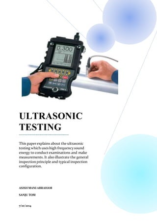
  • 7. ULTRASONIC TESTING EQUIPMENT Principle When ultrasonic waves from a piezo-electric crystal are made to propagate in a material through proper coupling it will be partially reflected or refracted when there is a change in medium or an interface , say the presence of a discontinuity or the opposite surface of the sound entry. The energy of the reflected ultrasonic waves depends upon the severity of the defect, the area or the orientation with respect to the direction of sound entry. The reflected wave is picked by a receiver and amplified for evaluation. Major Components of Ultrasonic Testing Equipment. I. Pulse Generator: It energise the timer and pulser transmitter. II. Pulse Transmitter: It energise the piezoelectric crystal in short pulses of regular interval . III. Probes: It generates the longitudinal sound waves and or shear sound waves. IV. Receiver : It receives the electrical signal and amplify the signals and feed it in to sweep and marker circuits.
  • 8. V. Sweep Circuits: The horizontal line or base line of the ultrasonic testing screen is controlled by sweep circuits. Normally the value of sweep reads from left to right at fixed points. VI. Marker Circuits: The amount of refraction in a particular area is displayed in CRT screen with the help of a marker circuit. VII. Timer: It is the heart of the equipment. It is the source of all timing signals in the UT equipment. PROBES A probe sends a sound wave in to a test material. There are two indications , one from the initial pulse of the probe , and the second due to the backwall echo. A defect creates a third indication and simultaneously reduces the amplitude of the backwall indication.
  • 9. TYPESOF PROBES  Normal Probe  Angular Probe  T-R Probe Normal Probes It is used to inspect thickness and measure flaws on bars, plates, casting, forgings and extrusions. Structure Of Normal Probe
  • 10. Calibration of Normal Probe Calibration Block Used: IIW V1 Block. Input Values: Angle =0 degree Range =100 Velocity =5920 m/s Mode = T+R Steps:  Horizontal Linearity Checking  Vertical Checking H1/H2 = H3/H4
  • 11.  Sensitivity Check S = Wavelength/2 Wavelength = Velocity/Frequency =(6000*1000)/(4*1000000) = 1.5mm S= 1.5/2 =0.75mm  Resolution Check  Amplitude Check dB = 20 log ( H2 /H1)  Penetration Check Set Range=200 and Frequency= 25dB Angle Probes In this the echo of a discontinuity on the instrument display does not give us any direct information about its position in the material. The only available information for determination of the reflector position is the scale position and therefore the sound path, this means the distance of the discontinuity from the index point of the probe. The mathematics of the right angled triangle help us to evaluate the surface distance and the depth of a reflector which are both important for ultrasonic testing.
  • 12. Calibration of Angle Probe Calibration Block Used: IIW V2 Block
  • 13. Input Values: Angle = 70 degree Range = 100mm Velocity = 3250 m/s Mode = T+R Steps:  Horizontal Linearity Checking  Sensitivity Checking