SlideShare a Scribd company logo
1 of 6
Download to read offline
International Research Journal of Engineering and Technology (IRJET) e-ISSN: 2395-0056
Volume: 04 Issue: 09 | Sep -2017 www.irjet.net p-ISSN: 2395-0072
© 2017, IRJET | Impact Factor value: 5.181 | ISO 9001:2008 Certified Journal | Page 1096
A Review of Vortex Tube Refrigeration System
Sufiyan Siddiqui1, Umme Hani Khan2, Ajit Rakhonde3, Shaikh Muzammil4
1,3,4 Student, Dept. of Mechanical Engineering, STC College, Khamgaon, Maharashtra, India.
2Student, Dept. of Mechanical Engineering, GPK College , Khamgaon, Maharashtra, India.
---------------------------------------------------------------------***---------------------------------------------------------------------
Abstract –Refrigeration plays an important role in
developing countries, primarily for the preservation of food,
medicine, and for air conditioning. Conventionalrefrigeration
systems are using Freon as refrigerant. As they are the main
cause for depletion of ozone layer, extensive research work
is going on alternate refrigeration systems. Vortex tube is a
non conventional cooling device, having no moving parts
which will produce cold air and hot air from the source of
compressed air without affecting the environment. When a
high pressure air is tangentially injected into vortex chamber
a strong vortex flow will be created which will besplitintotwo
air streams, one hot stream and the other is cold stream at its
ends. An experimental investigation is to be performed in
order to realize the behavior of a vortex tube system. In this
work attention has to be focused on the classification of the
parameters affecting vortex tube operation. The effective
parameters are divided into two different types, namely
geometrical and thermo-physical ones. A reliable test rig is to
be designed and constructed to investigate the effect of
geometrical parameters i.e. Diameterandlengthof maintube,
diameter of outlet orifice, shape of entrance nozzle. Thermo-
physical parameters are inlet gas pressure, type of gas, cold
gas mass ratio and moisture of inlet gas.
Key Words: Vortex Chamber, Refrigeration System, Vortex
Tube Design, Casing, Cooling Effect, Thermal Separation.
1.INTRODUCTION
The vortex tube was invented by a student named G.J
Ranque in 1932. He was able to create two streams with
different temperatures, using a highly compressed inlet
pressure supply. In 1945, a German physicist Rudolf Hilsch
improved the vortex tube designofRanqueandhe published
his work in a scientific paper. This publication of Hilsch was
widely read and was very well accepted by the scientific
community and thereby the energy separation phenomena
in the vortex tube became a topic of great interest. Even
though, Hilsch fabricated less than optimized vortex tube
geometry, he was able to measure the temperature
difference between the inlet stream and the outlet streams;
however he was not able to explain the physical process
behind this effect. This device was later named the Ranque-
Hilsch Vortex tube acknowledging the work doneby both G.J
Ranque and Hilsch.
Fig -1: Schematic diagram of a Vortex tube and the
Phenomena of flow reversal
The vortex tube functions as a device capable ofseparatinga
compressed air stream into hot and cold streams with
different mass fractions. This phenomenon is referred to as
energy (temperature) separation. A vortex tube consists of
one or more tangential inlet nozzles, an axial tube with a
vortex chamber, a cold gas outlet and a hot gas outlet. Dust
free dehumidified compressed air in the range of 5 to 6 bars
is injected into the vortex chamber tangentially through the
inlet nozzles. As the air acceleratesthroughtheinletnozzles,
it exits into a cylindrical section with a high angular velocity
which generates an intense swirling flow. The gas then
proceeds towards the hot outlet with the conical back
pressure control valve. However, not all the flow exits
through the control valve. A portion of the gas reverses its
direction and moves axially along the center of the tube
towards the cold outlet, against the oncoming hot swirling
flow.
As the reversed flow move towards the cold exit the thermal
energy possessed by the core flow is transferred to the
peripheral region of the flow. This results in the peripheral
flow temperature exceeding the inlet gas temperature. The
peripheral flow exits through the annularspacebetween the
tube wall and the conical valve at the hot outlet, whereasthe
core flow exits through the cold outlet orifice. The relative
mass flow rates of hot and cold gases are controlled by the
conical back pressure valve at the hot outlet. This energy
separation phenomenon is known as Ranque effect.
International Research Journal of Engineering and Technology (IRJET) e-ISSN: 2395-0056
Volume: 04 Issue: 09 | Sep -2017 www.irjet.net p-ISSN: 2395-0072
© 2017, IRJET | Impact Factor value: 5.181 | ISO 9001:2008 Certified Journal | Page 1097
1.1. Literature Review
A Review explained the working principle of vortex tube. A
detailed description of the parts of vortex tube has been
highlighted. Literature review is to understand the effect of
various parameters like inlet pressure of air, number of
nozzles, cold orifice diameter and hot end valve angle on the
performance of vortex tube. Alsobytheliterature reviewitis
clear that there is no theory so perfect, which gives the
satisfactory explanation of the vortex tube phenomenon. A
detailed study has been carriedouttounderstandthereason
of the splitting of air stream. The experimental results show
that the static temperature in the center of vortex tube is
higher than that of the peripheral part.
Construction design of a vortex tube for several inlet
stagnation pressures the report deals with the numerical
models used to analyses the geometrical optimization of the
vortex tube. Turbulence models like ke model and rans
model are briefly described. The mainpurposeofthework is
to increase the amount of energy obtained at cold end.
2. CONSTRUCTION
Fig-2: Actual vortex tube
2.1. Components Of Vortex Tube
Fig -3: Diagrammatic Representation of Vortex Tube
2.1.1. Nozzle
A nozzle is a device designed to control the direction or
characteristics of a fluid flow (especially to increasevelocity)
as it exists (or enters) an enclosed chamber or pipe.
Fig -4: Spiral Nozzle
Fig -5: Nozzle of normal rectangle
2.1.2. Diaphragm
A diaphragm is asheet of a semi flexible materialanchoredat
its periphery and most often round in shape. It serves either
as a barrier between two chambers, moving slightly up into
one chamber down into the other depending on the
differences in pressure, or as a device that vibrates when
certain frequency are applied to it.
2.1.3. Valve
A device used for controlling the flow of fluid in the pipe or
other enclosure. Control is by means of a movable element
that opens, shuts, or partiallyobstructsanopeninginpassage
way.
2.1.4. Hot air side
Hot side is cylindrical in cross section and is of different
length as per design.
2.1.5. Cold air side
Cold side is cylindrical portion through which cold air is
passed.
2.1.6. Chamber
Chamber is portion of nozzle and facilities the tangential
entry of high velocity air stream into hot side. Generally the
International Research Journal of Engineering and Technology (IRJET) e-ISSN: 2395-0056
Volume: 04 Issue: 09 | Sep -2017 www.irjet.net p-ISSN: 2395-0072
© 2017, IRJET | Impact Factor value: 5.181 | ISO 9001:2008 Certified Journal | Page 1098
chambers noncircular form,but theyaregraduallyconverted
into spiral form.
2.1.7. Diffuser
Diffuser is the device that allows the high velocity air to
expand and lowers the temperatureaswellaspressureofthe
air. By the installation of a diffuser it affects the temperature
of cold air.
3. DESIGN AND CONSTRUCTIONAL FEATURES
In general, there are two design features associated with a
vortex tube, namely, maximum temperature drop vortex
tube design for producing small quantity ofairwithverylow
temperatures and maximum cooling effect vortex tube
design for producing large quantity of air with moderate
temperatures. These two design considerations have been
used in study for increasing the heat transfer rate during
forward motion for swirl air and reversed flow of axial air.
The parameters investigated in the study, to understand
their inter-relationships and their effect on theperformance
of the vortex tube are:
 Nozzle diameter
 Cold orifice diameter
 Length of the tube
 Area at the hot end
Fig -6: Modified Casing of Vortex Tube
4. Material Used For Vortex Tube Components
The material for cold end (inlet cap) is MS, while the hot end
is manufactured in Brass for its good thermal conductivity
and rest of part are manufactured in mild steel for reducing
its overall cost and machining cost. A vortex tube of size
11.04 mm diameters of MS was selected. The casing of the
vortex tube was a 27 mm long MS cylinder. Two sets of
nozzles were made and each set consisted of two nozzles.
The first set of nozzles had a 32.7 mm diameterholeandwas
21 mm long, whereas the second set nozzles had a 33.0 mm
Outer diameter and was 12 mm long. Similarly, two cold
orifices are used having taperholediametersfrom4.5mmto
9.0 mm, respectively. A conical valve made of mild steel was
provided on the right hand side of the tube to regulate the
flow.
5. WORKING
Fig -7: Working of Vortex Tube
Compressed air is passed through the nozzle as
shown in Fig. Here, air expands and acquires high velocity
due to particular shape of the nozzle. Avortexflowiscreated
in the chamber and air travels in spiral like motion along the
periphery of the hot side. This flow is restricted by the valve.
When the pressure of the air near valve is made more than
outside by partly closing the valve, a reversed axial flow
through the core of the hot side starts from high-pressure
region to low-pressure region. During this process, heat
transfer takes place between reversed stream and forward
stream. Therefore, air stream through the core gets cooled
below the inlet temperature of the air in the vortex tube,
while air stream in forward direction gets heated up. The
cold stream is escaped through the diaphragm hole into the
cold side, while hot stream is passed through the opening of
the valve. By controlling the opening of the valve, the
quantity of the cold air and its temperature can be varied.
5.1. Temperature Separation Effect
The Vortex Tube Creates two types of vortices: free and
forced. In a free vortex (like a whirlpool)theangularvelocity
of a fluid particle increases as it moves toward the Center of
the vortex-that is, the closer a particle of fluid istothecenter
of a vortex, the faster it rotates. In a forced vortex, the
velocity is directly, proportional to the radius of the vortex-
the closer the center, the slower the velocity. In a vortex
tube, the outer (hot) air stream is a free vortex. The inner
(cold) air stream is a forcedvortex.Therotational movement
of the forced vortex is controlled by the free vortex (hot air
stream). The turbulence of both the hot and cold air streams
causes the layers to be locked together in a single, rotational
International Research Journal of Engineering and Technology (IRJET) e-ISSN: 2395-0056
Volume: 04 Issue: 09 | Sep -2017 www.irjet.net p-ISSN: 2395-0072
© 2017, IRJET | Impact Factor value: 5.181 | ISO 9001:2008 Certified Journal | Page 1099
mass. The inner air stream flows through the hollow core of
the outer air stream at a slower velocity than the outer air
stream. Since the energy is proportional to the square of the
velocity, the cold air stream loses its energy by heattransfer.
This allows energy to flow from the inner air stream to the
outer air stream as heat creating a cold inner air stream.
Fig -8: Temperature Separation in Vortex Tube
6. CLASSIFICATIONS OF THE VORTEX TUBE
Generally, the vortex tube can be classified into two types.
One is the counter-flow type (often referred to as the
standard type) and the other the parallel or uni-flow type.
6.1. Counter-flow vortex tube
Fig -9: Counter-Flow Vortex Tube
The counter-flow vortex tube, as shown in Fig 9 consists of
an entrance block of nozzle connections with a central
orifice, a vortex tube (or hot tube) and a cone-shaped valve.
A source of compressed gas (e.g. air) at high pressure enters
the vortex tube tangentially through one or more inlet
nozzles at a high velocity. The expanding air inside the tube
then creates a rapidly spinning vortex. The airflowsthrough
the tube rather than pass through the central orifice located
next to the nozzles because the orifice is of much smaller
diameter than the tube. The length of the tube is typically
between 30 and 50 tube diameters, and no optimum value
has been determined between these limits. As the air
expands down the tube, the pressure drops sharply to a
value slightly above atmospheric pressure, and the air
velocity can approach the speed of sound. Centrifugal action
will keep this constrained vortex closetotheinnersurface of
the tube.
The air that escapes at the other end of the tube can be
varied by a flow-control valve, usually shaped as a cone. The
amount of air released is between 30% and 70% of the total
airflow in the tube. The remainder of the air is returned
through the centre of the tube, along its axis as a counter-
flowing stream. Once a vortex is set up in the tube, the air
near the axis cools down while the air at periphery heats up
in comparison with the inlet temperature.Thisphenomenon
is known as temperature separation effect (also called the
Ranque–Hilsch effect). As a result, the gas escaping through
the orifice is cold and the hot gas flows out in the other
direction. A remarkable feature of this device is the absence
of moving parts and simplicity of operation.
6.2. Uni-flow vortex tube
Fig -10: Uni-Flow or Parallel Flow Vortex Tube
The uni-flow vortex tube comprises an entrance block of
inlet nozzles, a vortex tube and a cone-shaped valve with a
central orifice. Unlike the more popular counter-flow
version, the cold air exit is located concentrically with the
annular exit for the hot air. The operation of the uni-flow
vortex tube is similar to the operation of the counter-flow
one. The temperatures of the air leaving the hot and cold
ends can differ by as much as 140–160 1C, but extremes of
up to 230 1C have been measured by Comassar. In general,
the practical low-temperature limit for the cold air stream is
_40 1C, although temperatures as low as _50 1C have been
obtained with research equipment. The practical limit for
the high temperature is 190 1C, but temperatures in excess
of 225 1C have been observed by Bruno. The main
applications of the vortex tube are in those areas where
compactness, reliability, and low equipment costs are the
major factors and the operating efficiency is of no
consequence. Some typical applications are cooling devices
for airplanes, space suits and mines; instrumentcooling;and
industrial process coolers.
International Research Journal of Engineering and Technology (IRJET) e-ISSN: 2395-0056
Volume: 04 Issue: 09 | Sep -2017 www.irjet.net p-ISSN: 2395-0072
© 2017, IRJET | Impact Factor value: 5.181 | ISO 9001:2008 Certified Journal | Page 1100
7. ADVANTAGES
1. It uses air as refrigerant, so there is no leakage problem.
2. Vortex tube is simple in design and it avoids control
systems.
3. There are no moving parts in vortex tube.
4. It is light in weight and requires less space.
5. Initial cost is low and its working expenses are also less,
where compressed air is readily available.
6. Maintenance is simple and no skilled labours are
required.
8. DISADVANTAGES
1. It has low co-efficient of performance COP.
2. It has limited capacity and only small portion of the
compressed air appearing as the cold air limits its wide
use in practice.
3. Only used for spot cooling purpose.
4. Required low pressure range.
9. APPLICATIONS
5.
1. Vortex tubes are extremely small and as it produce hot
as well as cold air. It may be of use in industries where
both are simultaneously required.
2. Temperature as low as –500C can be obtained without
any difficulty, so it is very much useful in industries for
spot cooling of electronic components.
3. It is commonly used for body cooling of the workers in
mines.
4. Vortex tubes are used for cooling of cutting tools
(lathes and mills, both manually-operated
and CNC machines) during machining.
5. Commercial vortex tubes are designed for industrial
applications to produce a temperature drop of up to
71 °C (127 °F). With no moving parts, no electricity, and
no Freon, a vortex tube can produce refrigeration up to
6,000 BTU/h (1,800 W) using only filtered compressed
air at 100 PSI (6.9 bar). A control valve in the hot air
exhaust adjusts temperatures, flows and refrigeration
over a wide range.
10. ASSUMPTIONS
1. The working medium is ideal gas-air.
2. There is no heat interaction of the computation domain
with the surroundings.
3. Flow is steady, turbulent and compressible.
4. Body force is negligible.
11. CONCLUSIONS
A simple model of the Vortex Tube isdescribedthatcaptures
the physics related to one possible operating mechanism.
The model is shown to faithfully reproduce a limited set of
data if two empirical parameters are adjusted. The semi-
empirical model is subsequently used to evaluate the
potential performance benefit associated with replacing the
throttling valve in a refrigeration system with an
approximately optimized Vortex Tube. An experimental
study on the temperature separation in the Vortex Tube has
been carried out and this research finding can be
summarized as follows:
1. Temperature difference increases with increase in Inlet
Pressure.
2. Availability destruction decreases with increase in tube
length due to the increase in temperature difference.
3. Efficient working point of the existing design is at a cold
mass fraction 0.84 for an inlet pressure of 5bar.
4. Availability destruction is less in the case ofVortexTube
operation with two nozzles than with one nozzle due to
the increase in temperature difference.
5. The increase of the number of inlet nozzles led tohigher
temperature separation in the Vortex Tube.
6. Using the tube with insulation to reduce energy loss to
surroundings gave a higher temperature separation in
the tube than that without insulation around 2-3℃ for
the cold tube and 2-5℃ for the hot Tube.
7. The performance of a conventional vapor compression
refrigeration cycle cannot be augmented through the
application of a Vortex Tube because no temperature
separation can occur beneath the vapor dome.
8. The performance of a vapor compression cycle
operating in the near supercritical region, such as
carbon dioxide refrigeration cycle, is negligibly
increased by the application of a Vortex Tube.
12. FUTURE SCOPE
As we all know there are no limits for improvements in any
kind of work or we can say nothing is best. There is always
scope for improvements in present work. So, Vortex tube is
not an exception. Several investigators have modified the in
geometric design of present vortextubeandtestedfor better
performance. But there are still somanyoptionsavailableon
which experiments can be done. After some experimental
analysis work studied which is done by various researchers,
on geometrical modificationsforimprovingtheperformance
of vortex tube are as listed below:
1. We can increase number of inlet air entries.
2. Guiding element inside the Vortex tube can be provided
for guiding inlet air circumferentially towards hot end.
3. Experiments are also possible with varyingthelengthof
Cold ends and Hot ends.
4. Same Vortex tube as we have manufactured can be
tested by using water as cooling agent.
5. We can try some modification in the geometry of
convergent nozzle with the help of CFD analysis.
International Research Journal of Engineering and Technology (IRJET) e-ISSN: 2395-0056
Volume: 04 Issue: 09 | Sep -2017 www.irjet.net p-ISSN: 2395-0072
© 2017, IRJET | Impact Factor value: 5.181 | ISO 9001:2008 Certified Journal | Page 1101
6. We can try the same geometry in different material and
compare it to find the dependency on material of the
vortex tube.
ACKNOWLEDGEMENT
I take this opportunity to express my heartfelt gratitude to
my guide Prof. Mandar Tawlarkar and head of department,
Prof. Anand Paralkar, department of Mechanical
Engineering, STC school of poly, Khamgaon, for her kind co-
operation, constant Encouragement and suggestion and
capable guidance during the research without which it
would have been difficult to proceed with.
REFERENCES
[1] G. J.Ranque, “Method and apparatusforobtaining froma
fluid under pressure two outputs of fluid at different
temperatures,” 1934.
[2] G.W.Scheper, “The vortex tube; internal flow data and a
heat transfer theory,” 1951.
[3] Ahlborn and S. Groves, “Flow in a vortex tube,” 1997.
[4] Marquesa C.H., Isoldia L.A., Santos E.D. Rocha L.A,
‘‘Constructional Design of a Vortex Tube,’’2002.
[5] Prof. U.S.P. Shet, Prof. T. Sundararajan and Prof. J.M.
Mallikarjuna, “Working, application & advantages of
vortex tube,” 2004.
[6] N.Pourmahmoud,S.Akhesmeh,“Numerical Investigation
of the Thermal Separation in a Vortex Tube” 1998.
[7] R. Shamsoddini, A. H. Nezhad, ‘‘Numerical analysisofthe
effects of nozzles number on the flow and power of
cooling of a vortex tube, 2010.
[8] S. Nimbalkar and M. R. Muller, “An experimental
investigation of the optimum geometry for the cold end
orifice of a vortex tube, Applied Thermal Engineering,”
2009.
[9] Ahlborn, B. and J. Gordon, “The vortex tube as a
classical thermodynamic refrigeration cycle,” 2000.
[10] A Textbook of Refrigeration andAirConditioning by
Arora & Domkundwar, Section No 2.1, 8.2, 10.8.
[11] Refrigeration and Air Conditioning by R. S. Khurmi,
Section No 1.1, 15.2
BIOGRAPHIES
Sufiyan Siddiqui is a final year
student in Mech Department, STC
school of poly, Khamgaon MS. His
research interest is Vortex Tube
Refrigeration System
Umme Hani Khan is a final year
student in Mech Department,
Government poly, Khamgaon MS.
His research interest is Vortex
Tube Refrigeration System
Ajit Rakhonde is a final year
student in Mech Department, STC
school of poly, Khamgaon MS. His
research interest is Vortex Tube
Refrigeration System
Shaikh Muzammil is a final year
student in Mech Department, STC
school of poly, Khamgaon MS. His
research interest is Vortex Tube
Refrigeration System

More Related Content

What's hot

Energy conservation in compressed air systems
Energy conservation in compressed air systemsEnergy conservation in compressed air systems
Energy conservation in compressed air systemsmohammed kazi
 
Refrigeration Basics
Refrigeration BasicsRefrigeration Basics
Refrigeration BasicsAlvin Bene
 
Condensers and cooling towers
Condensers and cooling towersCondensers and cooling towers
Condensers and cooling towersmrmayurgohil91
 
Difference Between Simple Vapour Compression cycle and simple vapour absorpti...
Difference Between Simple Vapour Compression cycle and simple vapour absorpti...Difference Between Simple Vapour Compression cycle and simple vapour absorpti...
Difference Between Simple Vapour Compression cycle and simple vapour absorpti...prasad ghare
 
Condenser and cooling tower
Condenser and cooling towerCondenser and cooling tower
Condenser and cooling towerYashvir Singh
 
Centrifugal Compressor
Centrifugal CompressorCentrifugal Compressor
Centrifugal CompressorAnkit Singh
 
Gas turbine 2 - regeneration and intercooling
Gas turbine   2 - regeneration and intercoolingGas turbine   2 - regeneration and intercooling
Gas turbine 2 - regeneration and intercoolingNihal Senanayake
 
Vapor Compression Refrigeration System
Vapor Compression Refrigeration System Vapor Compression Refrigeration System
Vapor Compression Refrigeration System Abduljalil Al-Abidi
 
What are the main components of a chiller and what do they do
What are the main components of a chiller and what do they doWhat are the main components of a chiller and what do they do
What are the main components of a chiller and what do they donycritetemp
 
Air refrigeration system by Bell Coleman cycle and Vortex tube
Air refrigeration system by Bell Coleman cycle and Vortex tubeAir refrigeration system by Bell Coleman cycle and Vortex tube
Air refrigeration system by Bell Coleman cycle and Vortex tubeaparnamalyala
 
Steam condensers - Part 5 (Air leakage and Condenser Performance)
Steam condensers - Part 5 (Air leakage and Condenser Performance)Steam condensers - Part 5 (Air leakage and Condenser Performance)
Steam condensers - Part 5 (Air leakage and Condenser Performance)AVDHESH TYAGI
 
Vapor compression refrigeration cycle
Vapor compression refrigeration cycleVapor compression refrigeration cycle
Vapor compression refrigeration cyclepradosh a c
 
PROJECT REPORT ON PELTIER REFRIGERATOR
PROJECT REPORT ON PELTIER REFRIGERATORPROJECT REPORT ON PELTIER REFRIGERATOR
PROJECT REPORT ON PELTIER REFRIGERATORram143526
 
Vapour compression refrigeration system
Vapour compression refrigeration systemVapour compression refrigeration system
Vapour compression refrigeration systemnaphis ahamad
 

What's hot (20)

Energy conservation in compressed air systems
Energy conservation in compressed air systemsEnergy conservation in compressed air systems
Energy conservation in compressed air systems
 
Refrigeration Basics
Refrigeration BasicsRefrigeration Basics
Refrigeration Basics
 
Condensers and cooling towers
Condensers and cooling towersCondensers and cooling towers
Condensers and cooling towers
 
Difference Between Simple Vapour Compression cycle and simple vapour absorpti...
Difference Between Simple Vapour Compression cycle and simple vapour absorpti...Difference Between Simple Vapour Compression cycle and simple vapour absorpti...
Difference Between Simple Vapour Compression cycle and simple vapour absorpti...
 
Chiller ppt
Chiller pptChiller ppt
Chiller ppt
 
Condenser and cooling tower
Condenser and cooling towerCondenser and cooling tower
Condenser and cooling tower
 
Centrifugal Compressor
Centrifugal CompressorCentrifugal Compressor
Centrifugal Compressor
 
Gas turbine 2 - regeneration and intercooling
Gas turbine   2 - regeneration and intercoolingGas turbine   2 - regeneration and intercooling
Gas turbine 2 - regeneration and intercooling
 
Vapor Compression Refrigeration System
Vapor Compression Refrigeration System Vapor Compression Refrigeration System
Vapor Compression Refrigeration System
 
Steam Turbines
Steam TurbinesSteam Turbines
Steam Turbines
 
What are the main components of a chiller and what do they do
What are the main components of a chiller and what do they doWhat are the main components of a chiller and what do they do
What are the main components of a chiller and what do they do
 
cooling tower
cooling towercooling tower
cooling tower
 
Air refrigeration system by Bell Coleman cycle and Vortex tube
Air refrigeration system by Bell Coleman cycle and Vortex tubeAir refrigeration system by Bell Coleman cycle and Vortex tube
Air refrigeration system by Bell Coleman cycle and Vortex tube
 
Steam condensers - Part 5 (Air leakage and Condenser Performance)
Steam condensers - Part 5 (Air leakage and Condenser Performance)Steam condensers - Part 5 (Air leakage and Condenser Performance)
Steam condensers - Part 5 (Air leakage and Condenser Performance)
 
Fan and Blowers
 Fan and Blowers Fan and Blowers
Fan and Blowers
 
Vapor compression refrigeration cycle
Vapor compression refrigeration cycleVapor compression refrigeration cycle
Vapor compression refrigeration cycle
 
Refrigeration
RefrigerationRefrigeration
Refrigeration
 
PROJECT REPORT ON PELTIER REFRIGERATOR
PROJECT REPORT ON PELTIER REFRIGERATORPROJECT REPORT ON PELTIER REFRIGERATOR
PROJECT REPORT ON PELTIER REFRIGERATOR
 
Vapour compression refrigeration system
Vapour compression refrigeration systemVapour compression refrigeration system
Vapour compression refrigeration system
 
VAM ppt
VAM  pptVAM  ppt
VAM ppt
 

Similar to A Review of Vortex Tube Refrigeration System

IRJET- Analysis & Testing Of Vortex Tube By Optimization Of Material
IRJET-  	  Analysis & Testing Of Vortex Tube By Optimization Of MaterialIRJET-  	  Analysis & Testing Of Vortex Tube By Optimization Of Material
IRJET- Analysis & Testing Of Vortex Tube By Optimization Of MaterialIRJET Journal
 
Experimental Analysis of Vortex Tube for Different Parameters
Experimental Analysis of  Vortex Tube for Different ParametersExperimental Analysis of  Vortex Tube for Different Parameters
Experimental Analysis of Vortex Tube for Different ParametersIRJET Journal
 
Vortex Tube Refrigeration: Research, Design and Fabrication
Vortex Tube Refrigeration: Research, Design and FabricationVortex Tube Refrigeration: Research, Design and Fabrication
Vortex Tube Refrigeration: Research, Design and FabricationIRJET Journal
 
IRJET- A Review Paper on Analysis of Vortex Tube Cold Outlet for Radiator...
IRJET-  	  A Review Paper on Analysis of Vortex Tube Cold Outlet for Radiator...IRJET-  	  A Review Paper on Analysis of Vortex Tube Cold Outlet for Radiator...
IRJET- A Review Paper on Analysis of Vortex Tube Cold Outlet for Radiator...IRJET Journal
 
IRJET- Design and Analysis of Vortex Tube Refrigeration
IRJET-  	  Design and Analysis of Vortex Tube RefrigerationIRJET-  	  Design and Analysis of Vortex Tube Refrigeration
IRJET- Design and Analysis of Vortex Tube RefrigerationIRJET Journal
 
Ijri te-03-011 performance testing of vortex tubes with variable parameters
Ijri te-03-011 performance testing of vortex tubes with variable parametersIjri te-03-011 performance testing of vortex tubes with variable parameters
Ijri te-03-011 performance testing of vortex tubes with variable parametersIjripublishers Ijri
 
Review Paper on Experimental Analysis of Vortex Tube
Review Paper on Experimental Analysis of Vortex TubeReview Paper on Experimental Analysis of Vortex Tube
Review Paper on Experimental Analysis of Vortex TubeIRJET Journal
 
CONVECTIVE HEAT TRANSFER ANALYSIS IN A HELICAL COIL
CONVECTIVE HEAT TRANSFER ANALYSIS IN A HELICAL COILCONVECTIVE HEAT TRANSFER ANALYSIS IN A HELICAL COIL
CONVECTIVE HEAT TRANSFER ANALYSIS IN A HELICAL COILIRJET Journal
 
Study and Analysis of Vortex Tube
Study and Analysis of Vortex TubeStudy and Analysis of Vortex Tube
Study and Analysis of Vortex Tubeinventionjournals
 
IRJET- Analysis of Temperature Decrement of Engine Coolant by Utilizing Vorte...
IRJET- Analysis of Temperature Decrement of Engine Coolant by Utilizing Vorte...IRJET- Analysis of Temperature Decrement of Engine Coolant by Utilizing Vorte...
IRJET- Analysis of Temperature Decrement of Engine Coolant by Utilizing Vorte...IRJET Journal
 
K10945 rac gajendra meena
K10945 rac gajendra meenaK10945 rac gajendra meena
K10945 rac gajendra meenagajendra005
 
IRJET- Modelling and CFD Simulation of Prototype of AC Plant Chiller On-Board...
IRJET- Modelling and CFD Simulation of Prototype of AC Plant Chiller On-Board...IRJET- Modelling and CFD Simulation of Prototype of AC Plant Chiller On-Board...
IRJET- Modelling and CFD Simulation of Prototype of AC Plant Chiller On-Board...IRJET Journal
 
IRJET-Experimental Study on Helical Tube Heat Exchanger by Varying Cross Sect...
IRJET-Experimental Study on Helical Tube Heat Exchanger by Varying Cross Sect...IRJET-Experimental Study on Helical Tube Heat Exchanger by Varying Cross Sect...
IRJET-Experimental Study on Helical Tube Heat Exchanger by Varying Cross Sect...IRJET Journal
 
IRJET- Analysis of Shell and Tube Heat Exchangers
IRJET- Analysis of Shell and Tube Heat ExchangersIRJET- Analysis of Shell and Tube Heat Exchangers
IRJET- Analysis of Shell and Tube Heat ExchangersIRJET Journal
 
ANALYSIS OF VAPOR COMPRESSION REFRIGERATION SYSTEM WITH DIFFERENT CONFIGURATI...
ANALYSIS OF VAPOR COMPRESSION REFRIGERATION SYSTEM WITH DIFFERENT CONFIGURATI...ANALYSIS OF VAPOR COMPRESSION REFRIGERATION SYSTEM WITH DIFFERENT CONFIGURATI...
ANALYSIS OF VAPOR COMPRESSION REFRIGERATION SYSTEM WITH DIFFERENT CONFIGURATI...ijiert bestjournal
 
Design and demonstration of heat pipe based waste heat recovery system
Design and demonstration of heat pipe based waste heat recovery systemDesign and demonstration of heat pipe based waste heat recovery system
Design and demonstration of heat pipe based waste heat recovery systemIRJET Journal
 
IRJET- An Experimental Study of the Effect of Capillary Tube in Different...
IRJET-  	  An Experimental Study of the Effect of Capillary Tube in Different...IRJET-  	  An Experimental Study of the Effect of Capillary Tube in Different...
IRJET- An Experimental Study of the Effect of Capillary Tube in Different...IRJET Journal
 

Similar to A Review of Vortex Tube Refrigeration System (20)

IRJET- Analysis & Testing Of Vortex Tube By Optimization Of Material
IRJET-  	  Analysis & Testing Of Vortex Tube By Optimization Of MaterialIRJET-  	  Analysis & Testing Of Vortex Tube By Optimization Of Material
IRJET- Analysis & Testing Of Vortex Tube By Optimization Of Material
 
Experimental Analysis of Vortex Tube for Different Parameters
Experimental Analysis of  Vortex Tube for Different ParametersExperimental Analysis of  Vortex Tube for Different Parameters
Experimental Analysis of Vortex Tube for Different Parameters
 
Vortex Tube Refrigeration: Research, Design and Fabrication
Vortex Tube Refrigeration: Research, Design and FabricationVortex Tube Refrigeration: Research, Design and Fabrication
Vortex Tube Refrigeration: Research, Design and Fabrication
 
IRJET- A Review Paper on Analysis of Vortex Tube Cold Outlet for Radiator...
IRJET-  	  A Review Paper on Analysis of Vortex Tube Cold Outlet for Radiator...IRJET-  	  A Review Paper on Analysis of Vortex Tube Cold Outlet for Radiator...
IRJET- A Review Paper on Analysis of Vortex Tube Cold Outlet for Radiator...
 
IRJET- Design and Analysis of Vortex Tube Refrigeration
IRJET-  	  Design and Analysis of Vortex Tube RefrigerationIRJET-  	  Design and Analysis of Vortex Tube Refrigeration
IRJET- Design and Analysis of Vortex Tube Refrigeration
 
Ijri te-03-011 performance testing of vortex tubes with variable parameters
Ijri te-03-011 performance testing of vortex tubes with variable parametersIjri te-03-011 performance testing of vortex tubes with variable parameters
Ijri te-03-011 performance testing of vortex tubes with variable parameters
 
Review Paper on Experimental Analysis of Vortex Tube
Review Paper on Experimental Analysis of Vortex TubeReview Paper on Experimental Analysis of Vortex Tube
Review Paper on Experimental Analysis of Vortex Tube
 
IJETAE_0416_55
IJETAE_0416_55IJETAE_0416_55
IJETAE_0416_55
 
CONVECTIVE HEAT TRANSFER ANALYSIS IN A HELICAL COIL
CONVECTIVE HEAT TRANSFER ANALYSIS IN A HELICAL COILCONVECTIVE HEAT TRANSFER ANALYSIS IN A HELICAL COIL
CONVECTIVE HEAT TRANSFER ANALYSIS IN A HELICAL COIL
 
Study and Analysis of Vortex Tube
Study and Analysis of Vortex TubeStudy and Analysis of Vortex Tube
Study and Analysis of Vortex Tube
 
IRJET- Analysis of Temperature Decrement of Engine Coolant by Utilizing Vorte...
IRJET- Analysis of Temperature Decrement of Engine Coolant by Utilizing Vorte...IRJET- Analysis of Temperature Decrement of Engine Coolant by Utilizing Vorte...
IRJET- Analysis of Temperature Decrement of Engine Coolant by Utilizing Vorte...
 
main
mainmain
main
 
K10945 rac gajendra meena
K10945 rac gajendra meenaK10945 rac gajendra meena
K10945 rac gajendra meena
 
IRJET- Modelling and CFD Simulation of Prototype of AC Plant Chiller On-Board...
IRJET- Modelling and CFD Simulation of Prototype of AC Plant Chiller On-Board...IRJET- Modelling and CFD Simulation of Prototype of AC Plant Chiller On-Board...
IRJET- Modelling and CFD Simulation of Prototype of AC Plant Chiller On-Board...
 
IRJET-Experimental Study on Helical Tube Heat Exchanger by Varying Cross Sect...
IRJET-Experimental Study on Helical Tube Heat Exchanger by Varying Cross Sect...IRJET-Experimental Study on Helical Tube Heat Exchanger by Varying Cross Sect...
IRJET-Experimental Study on Helical Tube Heat Exchanger by Varying Cross Sect...
 
IRJET- Analysis of Shell and Tube Heat Exchangers
IRJET- Analysis of Shell and Tube Heat ExchangersIRJET- Analysis of Shell and Tube Heat Exchangers
IRJET- Analysis of Shell and Tube Heat Exchangers
 
Seminar Report on heat pipes
Seminar Report on heat pipesSeminar Report on heat pipes
Seminar Report on heat pipes
 
ANALYSIS OF VAPOR COMPRESSION REFRIGERATION SYSTEM WITH DIFFERENT CONFIGURATI...
ANALYSIS OF VAPOR COMPRESSION REFRIGERATION SYSTEM WITH DIFFERENT CONFIGURATI...ANALYSIS OF VAPOR COMPRESSION REFRIGERATION SYSTEM WITH DIFFERENT CONFIGURATI...
ANALYSIS OF VAPOR COMPRESSION REFRIGERATION SYSTEM WITH DIFFERENT CONFIGURATI...
 
Design and demonstration of heat pipe based waste heat recovery system
Design and demonstration of heat pipe based waste heat recovery systemDesign and demonstration of heat pipe based waste heat recovery system
Design and demonstration of heat pipe based waste heat recovery system
 
IRJET- An Experimental Study of the Effect of Capillary Tube in Different...
IRJET-  	  An Experimental Study of the Effect of Capillary Tube in Different...IRJET-  	  An Experimental Study of the Effect of Capillary Tube in Different...
IRJET- An Experimental Study of the Effect of Capillary Tube in Different...
 

More from IRJET Journal

TUNNELING IN HIMALAYAS WITH NATM METHOD: A SPECIAL REFERENCES TO SUNGAL TUNNE...
TUNNELING IN HIMALAYAS WITH NATM METHOD: A SPECIAL REFERENCES TO SUNGAL TUNNE...TUNNELING IN HIMALAYAS WITH NATM METHOD: A SPECIAL REFERENCES TO SUNGAL TUNNE...
TUNNELING IN HIMALAYAS WITH NATM METHOD: A SPECIAL REFERENCES TO SUNGAL TUNNE...IRJET Journal
 
STUDY THE EFFECT OF RESPONSE REDUCTION FACTOR ON RC FRAMED STRUCTURE
STUDY THE EFFECT OF RESPONSE REDUCTION FACTOR ON RC FRAMED STRUCTURESTUDY THE EFFECT OF RESPONSE REDUCTION FACTOR ON RC FRAMED STRUCTURE
STUDY THE EFFECT OF RESPONSE REDUCTION FACTOR ON RC FRAMED STRUCTUREIRJET Journal
 
A COMPARATIVE ANALYSIS OF RCC ELEMENT OF SLAB WITH STARK STEEL (HYSD STEEL) A...
A COMPARATIVE ANALYSIS OF RCC ELEMENT OF SLAB WITH STARK STEEL (HYSD STEEL) A...A COMPARATIVE ANALYSIS OF RCC ELEMENT OF SLAB WITH STARK STEEL (HYSD STEEL) A...
A COMPARATIVE ANALYSIS OF RCC ELEMENT OF SLAB WITH STARK STEEL (HYSD STEEL) A...IRJET Journal
 
Effect of Camber and Angles of Attack on Airfoil Characteristics
Effect of Camber and Angles of Attack on Airfoil CharacteristicsEffect of Camber and Angles of Attack on Airfoil Characteristics
Effect of Camber and Angles of Attack on Airfoil CharacteristicsIRJET Journal
 
A Review on the Progress and Challenges of Aluminum-Based Metal Matrix Compos...
A Review on the Progress and Challenges of Aluminum-Based Metal Matrix Compos...A Review on the Progress and Challenges of Aluminum-Based Metal Matrix Compos...
A Review on the Progress and Challenges of Aluminum-Based Metal Matrix Compos...IRJET Journal
 
Dynamic Urban Transit Optimization: A Graph Neural Network Approach for Real-...
Dynamic Urban Transit Optimization: A Graph Neural Network Approach for Real-...Dynamic Urban Transit Optimization: A Graph Neural Network Approach for Real-...
Dynamic Urban Transit Optimization: A Graph Neural Network Approach for Real-...IRJET Journal
 
Structural Analysis and Design of Multi-Storey Symmetric and Asymmetric Shape...
Structural Analysis and Design of Multi-Storey Symmetric and Asymmetric Shape...Structural Analysis and Design of Multi-Storey Symmetric and Asymmetric Shape...
Structural Analysis and Design of Multi-Storey Symmetric and Asymmetric Shape...IRJET Journal
 
A Review of “Seismic Response of RC Structures Having Plan and Vertical Irreg...
A Review of “Seismic Response of RC Structures Having Plan and Vertical Irreg...A Review of “Seismic Response of RC Structures Having Plan and Vertical Irreg...
A Review of “Seismic Response of RC Structures Having Plan and Vertical Irreg...IRJET Journal
 
A REVIEW ON MACHINE LEARNING IN ADAS
A REVIEW ON MACHINE LEARNING IN ADASA REVIEW ON MACHINE LEARNING IN ADAS
A REVIEW ON MACHINE LEARNING IN ADASIRJET Journal
 
Long Term Trend Analysis of Precipitation and Temperature for Asosa district,...
Long Term Trend Analysis of Precipitation and Temperature for Asosa district,...Long Term Trend Analysis of Precipitation and Temperature for Asosa district,...
Long Term Trend Analysis of Precipitation and Temperature for Asosa district,...IRJET Journal
 
P.E.B. Framed Structure Design and Analysis Using STAAD Pro
P.E.B. Framed Structure Design and Analysis Using STAAD ProP.E.B. Framed Structure Design and Analysis Using STAAD Pro
P.E.B. Framed Structure Design and Analysis Using STAAD ProIRJET Journal
 
A Review on Innovative Fiber Integration for Enhanced Reinforcement of Concre...
A Review on Innovative Fiber Integration for Enhanced Reinforcement of Concre...A Review on Innovative Fiber Integration for Enhanced Reinforcement of Concre...
A Review on Innovative Fiber Integration for Enhanced Reinforcement of Concre...IRJET Journal
 
Survey Paper on Cloud-Based Secured Healthcare System
Survey Paper on Cloud-Based Secured Healthcare SystemSurvey Paper on Cloud-Based Secured Healthcare System
Survey Paper on Cloud-Based Secured Healthcare SystemIRJET Journal
 
Review on studies and research on widening of existing concrete bridges
Review on studies and research on widening of existing concrete bridgesReview on studies and research on widening of existing concrete bridges
Review on studies and research on widening of existing concrete bridgesIRJET Journal
 
React based fullstack edtech web application
React based fullstack edtech web applicationReact based fullstack edtech web application
React based fullstack edtech web applicationIRJET Journal
 
A Comprehensive Review of Integrating IoT and Blockchain Technologies in the ...
A Comprehensive Review of Integrating IoT and Blockchain Technologies in the ...A Comprehensive Review of Integrating IoT and Blockchain Technologies in the ...
A Comprehensive Review of Integrating IoT and Blockchain Technologies in the ...IRJET Journal
 
A REVIEW ON THE PERFORMANCE OF COCONUT FIBRE REINFORCED CONCRETE.
A REVIEW ON THE PERFORMANCE OF COCONUT FIBRE REINFORCED CONCRETE.A REVIEW ON THE PERFORMANCE OF COCONUT FIBRE REINFORCED CONCRETE.
A REVIEW ON THE PERFORMANCE OF COCONUT FIBRE REINFORCED CONCRETE.IRJET Journal
 
Optimizing Business Management Process Workflows: The Dynamic Influence of Mi...
Optimizing Business Management Process Workflows: The Dynamic Influence of Mi...Optimizing Business Management Process Workflows: The Dynamic Influence of Mi...
Optimizing Business Management Process Workflows: The Dynamic Influence of Mi...IRJET Journal
 
Multistoried and Multi Bay Steel Building Frame by using Seismic Design
Multistoried and Multi Bay Steel Building Frame by using Seismic DesignMultistoried and Multi Bay Steel Building Frame by using Seismic Design
Multistoried and Multi Bay Steel Building Frame by using Seismic DesignIRJET Journal
 
Cost Optimization of Construction Using Plastic Waste as a Sustainable Constr...
Cost Optimization of Construction Using Plastic Waste as a Sustainable Constr...Cost Optimization of Construction Using Plastic Waste as a Sustainable Constr...
Cost Optimization of Construction Using Plastic Waste as a Sustainable Constr...IRJET Journal
 

More from IRJET Journal (20)

TUNNELING IN HIMALAYAS WITH NATM METHOD: A SPECIAL REFERENCES TO SUNGAL TUNNE...
TUNNELING IN HIMALAYAS WITH NATM METHOD: A SPECIAL REFERENCES TO SUNGAL TUNNE...TUNNELING IN HIMALAYAS WITH NATM METHOD: A SPECIAL REFERENCES TO SUNGAL TUNNE...
TUNNELING IN HIMALAYAS WITH NATM METHOD: A SPECIAL REFERENCES TO SUNGAL TUNNE...
 
STUDY THE EFFECT OF RESPONSE REDUCTION FACTOR ON RC FRAMED STRUCTURE
STUDY THE EFFECT OF RESPONSE REDUCTION FACTOR ON RC FRAMED STRUCTURESTUDY THE EFFECT OF RESPONSE REDUCTION FACTOR ON RC FRAMED STRUCTURE
STUDY THE EFFECT OF RESPONSE REDUCTION FACTOR ON RC FRAMED STRUCTURE
 
A COMPARATIVE ANALYSIS OF RCC ELEMENT OF SLAB WITH STARK STEEL (HYSD STEEL) A...
A COMPARATIVE ANALYSIS OF RCC ELEMENT OF SLAB WITH STARK STEEL (HYSD STEEL) A...A COMPARATIVE ANALYSIS OF RCC ELEMENT OF SLAB WITH STARK STEEL (HYSD STEEL) A...
A COMPARATIVE ANALYSIS OF RCC ELEMENT OF SLAB WITH STARK STEEL (HYSD STEEL) A...
 
Effect of Camber and Angles of Attack on Airfoil Characteristics
Effect of Camber and Angles of Attack on Airfoil CharacteristicsEffect of Camber and Angles of Attack on Airfoil Characteristics
Effect of Camber and Angles of Attack on Airfoil Characteristics
 
A Review on the Progress and Challenges of Aluminum-Based Metal Matrix Compos...
A Review on the Progress and Challenges of Aluminum-Based Metal Matrix Compos...A Review on the Progress and Challenges of Aluminum-Based Metal Matrix Compos...
A Review on the Progress and Challenges of Aluminum-Based Metal Matrix Compos...
 
Dynamic Urban Transit Optimization: A Graph Neural Network Approach for Real-...
Dynamic Urban Transit Optimization: A Graph Neural Network Approach for Real-...Dynamic Urban Transit Optimization: A Graph Neural Network Approach for Real-...
Dynamic Urban Transit Optimization: A Graph Neural Network Approach for Real-...
 
Structural Analysis and Design of Multi-Storey Symmetric and Asymmetric Shape...
Structural Analysis and Design of Multi-Storey Symmetric and Asymmetric Shape...Structural Analysis and Design of Multi-Storey Symmetric and Asymmetric Shape...
Structural Analysis and Design of Multi-Storey Symmetric and Asymmetric Shape...
 
A Review of “Seismic Response of RC Structures Having Plan and Vertical Irreg...
A Review of “Seismic Response of RC Structures Having Plan and Vertical Irreg...A Review of “Seismic Response of RC Structures Having Plan and Vertical Irreg...
A Review of “Seismic Response of RC Structures Having Plan and Vertical Irreg...
 
A REVIEW ON MACHINE LEARNING IN ADAS
A REVIEW ON MACHINE LEARNING IN ADASA REVIEW ON MACHINE LEARNING IN ADAS
A REVIEW ON MACHINE LEARNING IN ADAS
 
Long Term Trend Analysis of Precipitation and Temperature for Asosa district,...
Long Term Trend Analysis of Precipitation and Temperature for Asosa district,...Long Term Trend Analysis of Precipitation and Temperature for Asosa district,...
Long Term Trend Analysis of Precipitation and Temperature for Asosa district,...
 
P.E.B. Framed Structure Design and Analysis Using STAAD Pro
P.E.B. Framed Structure Design and Analysis Using STAAD ProP.E.B. Framed Structure Design and Analysis Using STAAD Pro
P.E.B. Framed Structure Design and Analysis Using STAAD Pro
 
A Review on Innovative Fiber Integration for Enhanced Reinforcement of Concre...
A Review on Innovative Fiber Integration for Enhanced Reinforcement of Concre...A Review on Innovative Fiber Integration for Enhanced Reinforcement of Concre...
A Review on Innovative Fiber Integration for Enhanced Reinforcement of Concre...
 
Survey Paper on Cloud-Based Secured Healthcare System
Survey Paper on Cloud-Based Secured Healthcare SystemSurvey Paper on Cloud-Based Secured Healthcare System
Survey Paper on Cloud-Based Secured Healthcare System
 
Review on studies and research on widening of existing concrete bridges
Review on studies and research on widening of existing concrete bridgesReview on studies and research on widening of existing concrete bridges
Review on studies and research on widening of existing concrete bridges
 
React based fullstack edtech web application
React based fullstack edtech web applicationReact based fullstack edtech web application
React based fullstack edtech web application
 
A Comprehensive Review of Integrating IoT and Blockchain Technologies in the ...
A Comprehensive Review of Integrating IoT and Blockchain Technologies in the ...A Comprehensive Review of Integrating IoT and Blockchain Technologies in the ...
A Comprehensive Review of Integrating IoT and Blockchain Technologies in the ...
 
A REVIEW ON THE PERFORMANCE OF COCONUT FIBRE REINFORCED CONCRETE.
A REVIEW ON THE PERFORMANCE OF COCONUT FIBRE REINFORCED CONCRETE.A REVIEW ON THE PERFORMANCE OF COCONUT FIBRE REINFORCED CONCRETE.
A REVIEW ON THE PERFORMANCE OF COCONUT FIBRE REINFORCED CONCRETE.
 
Optimizing Business Management Process Workflows: The Dynamic Influence of Mi...
Optimizing Business Management Process Workflows: The Dynamic Influence of Mi...Optimizing Business Management Process Workflows: The Dynamic Influence of Mi...
Optimizing Business Management Process Workflows: The Dynamic Influence of Mi...
 
Multistoried and Multi Bay Steel Building Frame by using Seismic Design
Multistoried and Multi Bay Steel Building Frame by using Seismic DesignMultistoried and Multi Bay Steel Building Frame by using Seismic Design
Multistoried and Multi Bay Steel Building Frame by using Seismic Design
 
Cost Optimization of Construction Using Plastic Waste as a Sustainable Constr...
Cost Optimization of Construction Using Plastic Waste as a Sustainable Constr...Cost Optimization of Construction Using Plastic Waste as a Sustainable Constr...
Cost Optimization of Construction Using Plastic Waste as a Sustainable Constr...
 

Recently uploaded

Learn the concepts of Thermodynamics on Magic Marks
Learn the concepts of Thermodynamics on Magic MarksLearn the concepts of Thermodynamics on Magic Marks
Learn the concepts of Thermodynamics on Magic MarksMagic Marks
 
Bridge Jacking Design Sample Calculation.pptx
Bridge Jacking Design Sample Calculation.pptxBridge Jacking Design Sample Calculation.pptx
Bridge Jacking Design Sample Calculation.pptxnuruddin69
 
COST-EFFETIVE and Energy Efficient BUILDINGS ptx
COST-EFFETIVE  and Energy Efficient BUILDINGS ptxCOST-EFFETIVE  and Energy Efficient BUILDINGS ptx
COST-EFFETIVE and Energy Efficient BUILDINGS ptxJIT KUMAR GUPTA
 
"Lesotho Leaps Forward: A Chronicle of Transformative Developments"
"Lesotho Leaps Forward: A Chronicle of Transformative Developments""Lesotho Leaps Forward: A Chronicle of Transformative Developments"
"Lesotho Leaps Forward: A Chronicle of Transformative Developments"mphochane1998
 
Computer Lecture 01.pptxIntroduction to Computers
Computer Lecture 01.pptxIntroduction to ComputersComputer Lecture 01.pptxIntroduction to Computers
Computer Lecture 01.pptxIntroduction to ComputersMairaAshraf6
 
Engineering Drawing focus on projection of planes
Engineering Drawing focus on projection of planesEngineering Drawing focus on projection of planes
Engineering Drawing focus on projection of planesRAJNEESHKUMAR341697
 
kiln thermal load.pptx kiln tgermal load
kiln thermal load.pptx kiln tgermal loadkiln thermal load.pptx kiln tgermal load
kiln thermal load.pptx kiln tgermal loadhamedmustafa094
 
Design For Accessibility: Getting it right from the start
Design For Accessibility: Getting it right from the startDesign For Accessibility: Getting it right from the start
Design For Accessibility: Getting it right from the startQuintin Balsdon
 
S1S2 B.Arch MGU - HOA1&2 Module 3 -Temple Architecture of Kerala.pptx
S1S2 B.Arch MGU - HOA1&2 Module 3 -Temple Architecture of Kerala.pptxS1S2 B.Arch MGU - HOA1&2 Module 3 -Temple Architecture of Kerala.pptx
S1S2 B.Arch MGU - HOA1&2 Module 3 -Temple Architecture of Kerala.pptxSCMS School of Architecture
 
Minimum and Maximum Modes of microprocessor 8086
Minimum and Maximum Modes of microprocessor 8086Minimum and Maximum Modes of microprocessor 8086
Minimum and Maximum Modes of microprocessor 8086anil_gaur
 
+97470301568>> buy weed in qatar,buy thc oil qatar,buy weed and vape oil in d...
+97470301568>> buy weed in qatar,buy thc oil qatar,buy weed and vape oil in d...+97470301568>> buy weed in qatar,buy thc oil qatar,buy weed and vape oil in d...
+97470301568>> buy weed in qatar,buy thc oil qatar,buy weed and vape oil in d...Health
 
HAND TOOLS USED AT ELECTRONICS WORK PRESENTED BY KOUSTAV SARKAR
HAND TOOLS USED AT ELECTRONICS WORK PRESENTED BY KOUSTAV SARKARHAND TOOLS USED AT ELECTRONICS WORK PRESENTED BY KOUSTAV SARKAR
HAND TOOLS USED AT ELECTRONICS WORK PRESENTED BY KOUSTAV SARKARKOUSTAV SARKAR
 
Navigating Complexity: The Role of Trusted Partners and VIAS3D in Dassault Sy...
Navigating Complexity: The Role of Trusted Partners and VIAS3D in Dassault Sy...Navigating Complexity: The Role of Trusted Partners and VIAS3D in Dassault Sy...
Navigating Complexity: The Role of Trusted Partners and VIAS3D in Dassault Sy...Arindam Chakraborty, Ph.D., P.E. (CA, TX)
 
Standard vs Custom Battery Packs - Decoding the Power Play
Standard vs Custom Battery Packs - Decoding the Power PlayStandard vs Custom Battery Packs - Decoding the Power Play
Standard vs Custom Battery Packs - Decoding the Power PlayEpec Engineered Technologies
 
Hazard Identification (HAZID) vs. Hazard and Operability (HAZOP): A Comparati...
Hazard Identification (HAZID) vs. Hazard and Operability (HAZOP): A Comparati...Hazard Identification (HAZID) vs. Hazard and Operability (HAZOP): A Comparati...
Hazard Identification (HAZID) vs. Hazard and Operability (HAZOP): A Comparati...soginsider
 
data_management_and _data_science_cheat_sheet.pdf
data_management_and _data_science_cheat_sheet.pdfdata_management_and _data_science_cheat_sheet.pdf
data_management_and _data_science_cheat_sheet.pdfJiananWang21
 
School management system project Report.pdf
School management system project Report.pdfSchool management system project Report.pdf
School management system project Report.pdfKamal Acharya
 
2016EF22_0 solar project report rooftop projects
2016EF22_0 solar project report rooftop projects2016EF22_0 solar project report rooftop projects
2016EF22_0 solar project report rooftop projectssmsksolar
 
Rums floating Omkareshwar FSPV IM_16112021.pdf
Rums floating Omkareshwar FSPV IM_16112021.pdfRums floating Omkareshwar FSPV IM_16112021.pdf
Rums floating Omkareshwar FSPV IM_16112021.pdfsmsksolar
 

Recently uploaded (20)

Learn the concepts of Thermodynamics on Magic Marks
Learn the concepts of Thermodynamics on Magic MarksLearn the concepts of Thermodynamics on Magic Marks
Learn the concepts of Thermodynamics on Magic Marks
 
Bridge Jacking Design Sample Calculation.pptx
Bridge Jacking Design Sample Calculation.pptxBridge Jacking Design Sample Calculation.pptx
Bridge Jacking Design Sample Calculation.pptx
 
COST-EFFETIVE and Energy Efficient BUILDINGS ptx
COST-EFFETIVE  and Energy Efficient BUILDINGS ptxCOST-EFFETIVE  and Energy Efficient BUILDINGS ptx
COST-EFFETIVE and Energy Efficient BUILDINGS ptx
 
"Lesotho Leaps Forward: A Chronicle of Transformative Developments"
"Lesotho Leaps Forward: A Chronicle of Transformative Developments""Lesotho Leaps Forward: A Chronicle of Transformative Developments"
"Lesotho Leaps Forward: A Chronicle of Transformative Developments"
 
Computer Lecture 01.pptxIntroduction to Computers
Computer Lecture 01.pptxIntroduction to ComputersComputer Lecture 01.pptxIntroduction to Computers
Computer Lecture 01.pptxIntroduction to Computers
 
Engineering Drawing focus on projection of planes
Engineering Drawing focus on projection of planesEngineering Drawing focus on projection of planes
Engineering Drawing focus on projection of planes
 
kiln thermal load.pptx kiln tgermal load
kiln thermal load.pptx kiln tgermal loadkiln thermal load.pptx kiln tgermal load
kiln thermal load.pptx kiln tgermal load
 
Design For Accessibility: Getting it right from the start
Design For Accessibility: Getting it right from the startDesign For Accessibility: Getting it right from the start
Design For Accessibility: Getting it right from the start
 
FEA Based Level 3 Assessment of Deformed Tanks with Fluid Induced Loads
FEA Based Level 3 Assessment of Deformed Tanks with Fluid Induced LoadsFEA Based Level 3 Assessment of Deformed Tanks with Fluid Induced Loads
FEA Based Level 3 Assessment of Deformed Tanks with Fluid Induced Loads
 
S1S2 B.Arch MGU - HOA1&2 Module 3 -Temple Architecture of Kerala.pptx
S1S2 B.Arch MGU - HOA1&2 Module 3 -Temple Architecture of Kerala.pptxS1S2 B.Arch MGU - HOA1&2 Module 3 -Temple Architecture of Kerala.pptx
S1S2 B.Arch MGU - HOA1&2 Module 3 -Temple Architecture of Kerala.pptx
 
Minimum and Maximum Modes of microprocessor 8086
Minimum and Maximum Modes of microprocessor 8086Minimum and Maximum Modes of microprocessor 8086
Minimum and Maximum Modes of microprocessor 8086
 
+97470301568>> buy weed in qatar,buy thc oil qatar,buy weed and vape oil in d...
+97470301568>> buy weed in qatar,buy thc oil qatar,buy weed and vape oil in d...+97470301568>> buy weed in qatar,buy thc oil qatar,buy weed and vape oil in d...
+97470301568>> buy weed in qatar,buy thc oil qatar,buy weed and vape oil in d...
 
HAND TOOLS USED AT ELECTRONICS WORK PRESENTED BY KOUSTAV SARKAR
HAND TOOLS USED AT ELECTRONICS WORK PRESENTED BY KOUSTAV SARKARHAND TOOLS USED AT ELECTRONICS WORK PRESENTED BY KOUSTAV SARKAR
HAND TOOLS USED AT ELECTRONICS WORK PRESENTED BY KOUSTAV SARKAR
 
Navigating Complexity: The Role of Trusted Partners and VIAS3D in Dassault Sy...
Navigating Complexity: The Role of Trusted Partners and VIAS3D in Dassault Sy...Navigating Complexity: The Role of Trusted Partners and VIAS3D in Dassault Sy...
Navigating Complexity: The Role of Trusted Partners and VIAS3D in Dassault Sy...
 
Standard vs Custom Battery Packs - Decoding the Power Play
Standard vs Custom Battery Packs - Decoding the Power PlayStandard vs Custom Battery Packs - Decoding the Power Play
Standard vs Custom Battery Packs - Decoding the Power Play
 
Hazard Identification (HAZID) vs. Hazard and Operability (HAZOP): A Comparati...
Hazard Identification (HAZID) vs. Hazard and Operability (HAZOP): A Comparati...Hazard Identification (HAZID) vs. Hazard and Operability (HAZOP): A Comparati...
Hazard Identification (HAZID) vs. Hazard and Operability (HAZOP): A Comparati...
 
data_management_and _data_science_cheat_sheet.pdf
data_management_and _data_science_cheat_sheet.pdfdata_management_and _data_science_cheat_sheet.pdf
data_management_and _data_science_cheat_sheet.pdf
 
School management system project Report.pdf
School management system project Report.pdfSchool management system project Report.pdf
School management system project Report.pdf
 
2016EF22_0 solar project report rooftop projects
2016EF22_0 solar project report rooftop projects2016EF22_0 solar project report rooftop projects
2016EF22_0 solar project report rooftop projects
 
Rums floating Omkareshwar FSPV IM_16112021.pdf
Rums floating Omkareshwar FSPV IM_16112021.pdfRums floating Omkareshwar FSPV IM_16112021.pdf
Rums floating Omkareshwar FSPV IM_16112021.pdf
 

A Review of Vortex Tube Refrigeration System

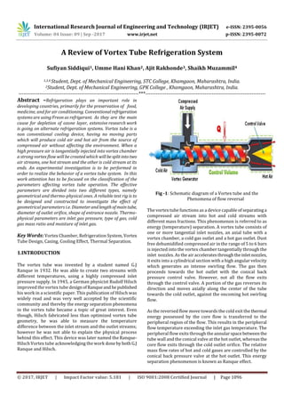
  • 1. International Research Journal of Engineering and Technology (IRJET) e-ISSN: 2395-0056 Volume: 04 Issue: 09 | Sep -2017 www.irjet.net p-ISSN: 2395-0072 © 2017, IRJET | Impact Factor value: 5.181 | ISO 9001:2008 Certified Journal | Page 1096 A Review of Vortex Tube Refrigeration System Sufiyan Siddiqui1, Umme Hani Khan2, Ajit Rakhonde3, Shaikh Muzammil4 1,3,4 Student, Dept. of Mechanical Engineering, STC College, Khamgaon, Maharashtra, India. 2Student, Dept. of Mechanical Engineering, GPK College , Khamgaon, Maharashtra, India. ---------------------------------------------------------------------***--------------------------------------------------------------------- Abstract –Refrigeration plays an important role in developing countries, primarily for the preservation of food, medicine, and for air conditioning. Conventionalrefrigeration systems are using Freon as refrigerant. As they are the main cause for depletion of ozone layer, extensive research work is going on alternate refrigeration systems. Vortex tube is a non conventional cooling device, having no moving parts which will produce cold air and hot air from the source of compressed air without affecting the environment. When a high pressure air is tangentially injected into vortex chamber a strong vortex flow will be created which will besplitintotwo air streams, one hot stream and the other is cold stream at its ends. An experimental investigation is to be performed in order to realize the behavior of a vortex tube system. In this work attention has to be focused on the classification of the parameters affecting vortex tube operation. The effective parameters are divided into two different types, namely geometrical and thermo-physical ones. A reliable test rig is to be designed and constructed to investigate the effect of geometrical parameters i.e. Diameterandlengthof maintube, diameter of outlet orifice, shape of entrance nozzle. Thermo- physical parameters are inlet gas pressure, type of gas, cold gas mass ratio and moisture of inlet gas. Key Words: Vortex Chamber, Refrigeration System, Vortex Tube Design, Casing, Cooling Effect, Thermal Separation. 1.INTRODUCTION The vortex tube was invented by a student named G.J Ranque in 1932. He was able to create two streams with different temperatures, using a highly compressed inlet pressure supply. In 1945, a German physicist Rudolf Hilsch improved the vortex tube designofRanqueandhe published his work in a scientific paper. This publication of Hilsch was widely read and was very well accepted by the scientific community and thereby the energy separation phenomena in the vortex tube became a topic of great interest. Even though, Hilsch fabricated less than optimized vortex tube geometry, he was able to measure the temperature difference between the inlet stream and the outlet streams; however he was not able to explain the physical process behind this effect. This device was later named the Ranque- Hilsch Vortex tube acknowledging the work doneby both G.J Ranque and Hilsch. Fig -1: Schematic diagram of a Vortex tube and the Phenomena of flow reversal The vortex tube functions as a device capable ofseparatinga compressed air stream into hot and cold streams with different mass fractions. This phenomenon is referred to as energy (temperature) separation. A vortex tube consists of one or more tangential inlet nozzles, an axial tube with a vortex chamber, a cold gas outlet and a hot gas outlet. Dust free dehumidified compressed air in the range of 5 to 6 bars is injected into the vortex chamber tangentially through the inlet nozzles. As the air acceleratesthroughtheinletnozzles, it exits into a cylindrical section with a high angular velocity which generates an intense swirling flow. The gas then proceeds towards the hot outlet with the conical back pressure control valve. However, not all the flow exits through the control valve. A portion of the gas reverses its direction and moves axially along the center of the tube towards the cold outlet, against the oncoming hot swirling flow. As the reversed flow move towards the cold exit the thermal energy possessed by the core flow is transferred to the peripheral region of the flow. This results in the peripheral flow temperature exceeding the inlet gas temperature. The peripheral flow exits through the annularspacebetween the tube wall and the conical valve at the hot outlet, whereasthe core flow exits through the cold outlet orifice. The relative mass flow rates of hot and cold gases are controlled by the conical back pressure valve at the hot outlet. This energy separation phenomenon is known as Ranque effect.
  • 2. International Research Journal of Engineering and Technology (IRJET) e-ISSN: 2395-0056 Volume: 04 Issue: 09 | Sep -2017 www.irjet.net p-ISSN: 2395-0072 © 2017, IRJET | Impact Factor value: 5.181 | ISO 9001:2008 Certified Journal | Page 1097 1.1. Literature Review A Review explained the working principle of vortex tube. A detailed description of the parts of vortex tube has been highlighted. Literature review is to understand the effect of various parameters like inlet pressure of air, number of nozzles, cold orifice diameter and hot end valve angle on the performance of vortex tube. Alsobytheliterature reviewitis clear that there is no theory so perfect, which gives the satisfactory explanation of the vortex tube phenomenon. A detailed study has been carriedouttounderstandthereason of the splitting of air stream. The experimental results show that the static temperature in the center of vortex tube is higher than that of the peripheral part. Construction design of a vortex tube for several inlet stagnation pressures the report deals with the numerical models used to analyses the geometrical optimization of the vortex tube. Turbulence models like ke model and rans model are briefly described. The mainpurposeofthework is to increase the amount of energy obtained at cold end. 2. CONSTRUCTION Fig-2: Actual vortex tube 2.1. Components Of Vortex Tube Fig -3: Diagrammatic Representation of Vortex Tube 2.1.1. Nozzle A nozzle is a device designed to control the direction or characteristics of a fluid flow (especially to increasevelocity) as it exists (or enters) an enclosed chamber or pipe. Fig -4: Spiral Nozzle Fig -5: Nozzle of normal rectangle 2.1.2. Diaphragm A diaphragm is asheet of a semi flexible materialanchoredat its periphery and most often round in shape. It serves either as a barrier between two chambers, moving slightly up into one chamber down into the other depending on the differences in pressure, or as a device that vibrates when certain frequency are applied to it. 2.1.3. Valve A device used for controlling the flow of fluid in the pipe or other enclosure. Control is by means of a movable element that opens, shuts, or partiallyobstructsanopeninginpassage way. 2.1.4. Hot air side Hot side is cylindrical in cross section and is of different length as per design. 2.1.5. Cold air side Cold side is cylindrical portion through which cold air is passed. 2.1.6. Chamber Chamber is portion of nozzle and facilities the tangential entry of high velocity air stream into hot side. Generally the
  • 3. International Research Journal of Engineering and Technology (IRJET) e-ISSN: 2395-0056 Volume: 04 Issue: 09 | Sep -2017 www.irjet.net p-ISSN: 2395-0072 © 2017, IRJET | Impact Factor value: 5.181 | ISO 9001:2008 Certified Journal | Page 1098 chambers noncircular form,but theyaregraduallyconverted into spiral form. 2.1.7. Diffuser Diffuser is the device that allows the high velocity air to expand and lowers the temperatureaswellaspressureofthe air. By the installation of a diffuser it affects the temperature of cold air. 3. DESIGN AND CONSTRUCTIONAL FEATURES In general, there are two design features associated with a vortex tube, namely, maximum temperature drop vortex tube design for producing small quantity ofairwithverylow temperatures and maximum cooling effect vortex tube design for producing large quantity of air with moderate temperatures. These two design considerations have been used in study for increasing the heat transfer rate during forward motion for swirl air and reversed flow of axial air. The parameters investigated in the study, to understand their inter-relationships and their effect on theperformance of the vortex tube are:  Nozzle diameter  Cold orifice diameter  Length of the tube  Area at the hot end Fig -6: Modified Casing of Vortex Tube 4. Material Used For Vortex Tube Components The material for cold end (inlet cap) is MS, while the hot end is manufactured in Brass for its good thermal conductivity and rest of part are manufactured in mild steel for reducing its overall cost and machining cost. A vortex tube of size 11.04 mm diameters of MS was selected. The casing of the vortex tube was a 27 mm long MS cylinder. Two sets of nozzles were made and each set consisted of two nozzles. The first set of nozzles had a 32.7 mm diameterholeandwas 21 mm long, whereas the second set nozzles had a 33.0 mm Outer diameter and was 12 mm long. Similarly, two cold orifices are used having taperholediametersfrom4.5mmto 9.0 mm, respectively. A conical valve made of mild steel was provided on the right hand side of the tube to regulate the flow. 5. WORKING Fig -7: Working of Vortex Tube Compressed air is passed through the nozzle as shown in Fig. Here, air expands and acquires high velocity due to particular shape of the nozzle. Avortexflowiscreated in the chamber and air travels in spiral like motion along the periphery of the hot side. This flow is restricted by the valve. When the pressure of the air near valve is made more than outside by partly closing the valve, a reversed axial flow through the core of the hot side starts from high-pressure region to low-pressure region. During this process, heat transfer takes place between reversed stream and forward stream. Therefore, air stream through the core gets cooled below the inlet temperature of the air in the vortex tube, while air stream in forward direction gets heated up. The cold stream is escaped through the diaphragm hole into the cold side, while hot stream is passed through the opening of the valve. By controlling the opening of the valve, the quantity of the cold air and its temperature can be varied. 5.1. Temperature Separation Effect The Vortex Tube Creates two types of vortices: free and forced. In a free vortex (like a whirlpool)theangularvelocity of a fluid particle increases as it moves toward the Center of the vortex-that is, the closer a particle of fluid istothecenter of a vortex, the faster it rotates. In a forced vortex, the velocity is directly, proportional to the radius of the vortex- the closer the center, the slower the velocity. In a vortex tube, the outer (hot) air stream is a free vortex. The inner (cold) air stream is a forcedvortex.Therotational movement of the forced vortex is controlled by the free vortex (hot air stream). The turbulence of both the hot and cold air streams causes the layers to be locked together in a single, rotational
  • 4. International Research Journal of Engineering and Technology (IRJET) e-ISSN: 2395-0056 Volume: 04 Issue: 09 | Sep -2017 www.irjet.net p-ISSN: 2395-0072 © 2017, IRJET | Impact Factor value: 5.181 | ISO 9001:2008 Certified Journal | Page 1099 mass. The inner air stream flows through the hollow core of the outer air stream at a slower velocity than the outer air stream. Since the energy is proportional to the square of the velocity, the cold air stream loses its energy by heattransfer. This allows energy to flow from the inner air stream to the outer air stream as heat creating a cold inner air stream. Fig -8: Temperature Separation in Vortex Tube 6. CLASSIFICATIONS OF THE VORTEX TUBE Generally, the vortex tube can be classified into two types. One is the counter-flow type (often referred to as the standard type) and the other the parallel or uni-flow type. 6.1. Counter-flow vortex tube Fig -9: Counter-Flow Vortex Tube The counter-flow vortex tube, as shown in Fig 9 consists of an entrance block of nozzle connections with a central orifice, a vortex tube (or hot tube) and a cone-shaped valve. A source of compressed gas (e.g. air) at high pressure enters the vortex tube tangentially through one or more inlet nozzles at a high velocity. The expanding air inside the tube then creates a rapidly spinning vortex. The airflowsthrough the tube rather than pass through the central orifice located next to the nozzles because the orifice is of much smaller diameter than the tube. The length of the tube is typically between 30 and 50 tube diameters, and no optimum value has been determined between these limits. As the air expands down the tube, the pressure drops sharply to a value slightly above atmospheric pressure, and the air velocity can approach the speed of sound. Centrifugal action will keep this constrained vortex closetotheinnersurface of the tube. The air that escapes at the other end of the tube can be varied by a flow-control valve, usually shaped as a cone. The amount of air released is between 30% and 70% of the total airflow in the tube. The remainder of the air is returned through the centre of the tube, along its axis as a counter- flowing stream. Once a vortex is set up in the tube, the air near the axis cools down while the air at periphery heats up in comparison with the inlet temperature.Thisphenomenon is known as temperature separation effect (also called the Ranque–Hilsch effect). As a result, the gas escaping through the orifice is cold and the hot gas flows out in the other direction. A remarkable feature of this device is the absence of moving parts and simplicity of operation. 6.2. Uni-flow vortex tube Fig -10: Uni-Flow or Parallel Flow Vortex Tube The uni-flow vortex tube comprises an entrance block of inlet nozzles, a vortex tube and a cone-shaped valve with a central orifice. Unlike the more popular counter-flow version, the cold air exit is located concentrically with the annular exit for the hot air. The operation of the uni-flow vortex tube is similar to the operation of the counter-flow one. The temperatures of the air leaving the hot and cold ends can differ by as much as 140–160 1C, but extremes of up to 230 1C have been measured by Comassar. In general, the practical low-temperature limit for the cold air stream is _40 1C, although temperatures as low as _50 1C have been obtained with research equipment. The practical limit for the high temperature is 190 1C, but temperatures in excess of 225 1C have been observed by Bruno. The main applications of the vortex tube are in those areas where compactness, reliability, and low equipment costs are the major factors and the operating efficiency is of no consequence. Some typical applications are cooling devices for airplanes, space suits and mines; instrumentcooling;and industrial process coolers.
  • 5. International Research Journal of Engineering and Technology (IRJET) e-ISSN: 2395-0056 Volume: 04 Issue: 09 | Sep -2017 www.irjet.net p-ISSN: 2395-0072 © 2017, IRJET | Impact Factor value: 5.181 | ISO 9001:2008 Certified Journal | Page 1100 7. ADVANTAGES 1. It uses air as refrigerant, so there is no leakage problem. 2. Vortex tube is simple in design and it avoids control systems. 3. There are no moving parts in vortex tube. 4. It is light in weight and requires less space. 5. Initial cost is low and its working expenses are also less, where compressed air is readily available. 6. Maintenance is simple and no skilled labours are required. 8. DISADVANTAGES 1. It has low co-efficient of performance COP. 2. It has limited capacity and only small portion of the compressed air appearing as the cold air limits its wide use in practice. 3. Only used for spot cooling purpose. 4. Required low pressure range. 9. APPLICATIONS 5. 1. Vortex tubes are extremely small and as it produce hot as well as cold air. It may be of use in industries where both are simultaneously required. 2. Temperature as low as –500C can be obtained without any difficulty, so it is very much useful in industries for spot cooling of electronic components. 3. It is commonly used for body cooling of the workers in mines. 4. Vortex tubes are used for cooling of cutting tools (lathes and mills, both manually-operated and CNC machines) during machining. 5. Commercial vortex tubes are designed for industrial applications to produce a temperature drop of up to 71 °C (127 °F). With no moving parts, no electricity, and no Freon, a vortex tube can produce refrigeration up to 6,000 BTU/h (1,800 W) using only filtered compressed air at 100 PSI (6.9 bar). A control valve in the hot air exhaust adjusts temperatures, flows and refrigeration over a wide range. 10. ASSUMPTIONS 1. The working medium is ideal gas-air. 2. There is no heat interaction of the computation domain with the surroundings. 3. Flow is steady, turbulent and compressible. 4. Body force is negligible. 11. CONCLUSIONS A simple model of the Vortex Tube isdescribedthatcaptures the physics related to one possible operating mechanism. The model is shown to faithfully reproduce a limited set of data if two empirical parameters are adjusted. The semi- empirical model is subsequently used to evaluate the potential performance benefit associated with replacing the throttling valve in a refrigeration system with an approximately optimized Vortex Tube. An experimental study on the temperature separation in the Vortex Tube has been carried out and this research finding can be summarized as follows: 1. Temperature difference increases with increase in Inlet Pressure. 2. Availability destruction decreases with increase in tube length due to the increase in temperature difference. 3. Efficient working point of the existing design is at a cold mass fraction 0.84 for an inlet pressure of 5bar. 4. Availability destruction is less in the case ofVortexTube operation with two nozzles than with one nozzle due to the increase in temperature difference. 5. The increase of the number of inlet nozzles led tohigher temperature separation in the Vortex Tube. 6. Using the tube with insulation to reduce energy loss to surroundings gave a higher temperature separation in the tube than that without insulation around 2-3℃ for the cold tube and 2-5℃ for the hot Tube. 7. The performance of a conventional vapor compression refrigeration cycle cannot be augmented through the application of a Vortex Tube because no temperature separation can occur beneath the vapor dome. 8. The performance of a vapor compression cycle operating in the near supercritical region, such as carbon dioxide refrigeration cycle, is negligibly increased by the application of a Vortex Tube. 12. FUTURE SCOPE As we all know there are no limits for improvements in any kind of work or we can say nothing is best. There is always scope for improvements in present work. So, Vortex tube is not an exception. Several investigators have modified the in geometric design of present vortextubeandtestedfor better performance. But there are still somanyoptionsavailableon which experiments can be done. After some experimental analysis work studied which is done by various researchers, on geometrical modificationsforimprovingtheperformance of vortex tube are as listed below: 1. We can increase number of inlet air entries. 2. Guiding element inside the Vortex tube can be provided for guiding inlet air circumferentially towards hot end. 3. Experiments are also possible with varyingthelengthof Cold ends and Hot ends. 4. Same Vortex tube as we have manufactured can be tested by using water as cooling agent. 5. We can try some modification in the geometry of convergent nozzle with the help of CFD analysis.
  • 6. International Research Journal of Engineering and Technology (IRJET) e-ISSN: 2395-0056 Volume: 04 Issue: 09 | Sep -2017 www.irjet.net p-ISSN: 2395-0072 © 2017, IRJET | Impact Factor value: 5.181 | ISO 9001:2008 Certified Journal | Page 1101 6. We can try the same geometry in different material and compare it to find the dependency on material of the vortex tube. ACKNOWLEDGEMENT I take this opportunity to express my heartfelt gratitude to my guide Prof. Mandar Tawlarkar and head of department, Prof. Anand Paralkar, department of Mechanical Engineering, STC school of poly, Khamgaon, for her kind co- operation, constant Encouragement and suggestion and capable guidance during the research without which it would have been difficult to proceed with. REFERENCES [1] G. J.Ranque, “Method and apparatusforobtaining froma fluid under pressure two outputs of fluid at different temperatures,” 1934. [2] G.W.Scheper, “The vortex tube; internal flow data and a heat transfer theory,” 1951. [3] Ahlborn and S. Groves, “Flow in a vortex tube,” 1997. [4] Marquesa C.H., Isoldia L.A., Santos E.D. Rocha L.A, ‘‘Constructional Design of a Vortex Tube,’’2002. [5] Prof. U.S.P. Shet, Prof. T. Sundararajan and Prof. J.M. Mallikarjuna, “Working, application & advantages of vortex tube,” 2004. [6] N.Pourmahmoud,S.Akhesmeh,“Numerical Investigation of the Thermal Separation in a Vortex Tube” 1998. [7] R. Shamsoddini, A. H. Nezhad, ‘‘Numerical analysisofthe effects of nozzles number on the flow and power of cooling of a vortex tube, 2010. [8] S. Nimbalkar and M. R. Muller, “An experimental investigation of the optimum geometry for the cold end orifice of a vortex tube, Applied Thermal Engineering,” 2009. [9] Ahlborn, B. and J. Gordon, “The vortex tube as a classical thermodynamic refrigeration cycle,” 2000. [10] A Textbook of Refrigeration andAirConditioning by Arora & Domkundwar, Section No 2.1, 8.2, 10.8. [11] Refrigeration and Air Conditioning by R. S. Khurmi, Section No 1.1, 15.2 BIOGRAPHIES Sufiyan Siddiqui is a final year student in Mech Department, STC school of poly, Khamgaon MS. His research interest is Vortex Tube Refrigeration System Umme Hani Khan is a final year student in Mech Department, Government poly, Khamgaon MS. His research interest is Vortex Tube Refrigeration System Ajit Rakhonde is a final year student in Mech Department, STC school of poly, Khamgaon MS. His research interest is Vortex Tube Refrigeration System Shaikh Muzammil is a final year student in Mech Department, STC school of poly, Khamgaon MS. His research interest is Vortex Tube Refrigeration System