This document serves as a detailed guide for designers and engineers on bridge jacking and blocking systems, outlining structural requirements, load considerations, and procedural guidelines. It covers various scenarios including new bridge designs and maintenance of existing structures, emphasizing the need for proper jacking arrangements and calculations. Additionally, it provides specific information on commercially available jacking cylinders suitable for different jacking situations.


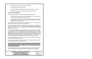


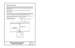

![Check Concrete Bearing:
With close proximity of jacks to each other and the edge of pier cap, assume the notional loaded
area A2 equal the loaded area A1 with uniform bearing as an initial assumption for sizing the
jacking baseplate.
[AASHTO 5.6.5]
Where per baseplate
per initial assumption
[AASHTO 5.5.4.2]
Try using a 10” x 10” steel baseplate, , and investigate A2.
The notional loaded area A2 is determined at a level beneath the loaded surface A1 as measured
by projecting the loads at a 2:1 slope as shown below.
The modification factor, m, is calculated two ways depending upon whether the loaded area is
subject to uniformly or non-uniformly distributed bearing stresses. Since two jacking cylinders are
required at a close spacing, let’s evaluated the concrete bearing requirements in two cases:
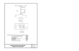
BRIDGE JACKING AND BLOCKING
SAMPLE CALCULATIONS
PART 2
DATE: 31Oct2019
SHEET 4 of 9
FILE NO. 28.04-4](https://image.slidesharecdn.com/bridgejackingsamplecalculation-240504062722-d9e6603c/85/Bridge-Jacking-Design-Sample-Calculation-pptx-31-320.jpg)
![Analysis Case 1 – Determine A2 and m assuming uniformly distributed bearing stress.
per baseplate
[AASHTO 5.6.5-3]
required per jack, OK
Analysis Case 2 – Determine A2 and m assuming non-uniformly distributed bearing stress.
per baseplate
[AASHTO 5.6.5-4]
required per jack, OK
BRIDGE JACKING AND BLOCKING
SAMPLE CALCULATIONS
PART 2
DATE: 31Oct2019
SHEET 5 of 9
FILE NO. 28.04-5](https://image.slidesharecdn.com/bridgejackingsamplecalculation-240504062722-d9e6603c/85/Bridge-Jacking-Design-Sample-Calculation-pptx-32-320.jpg)