The document discusses CT numbers, window width, and window level in computed tomography (CT) imaging. It provides the following key points:
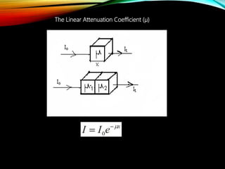
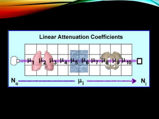
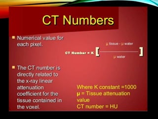
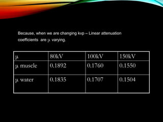
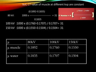
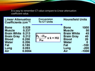
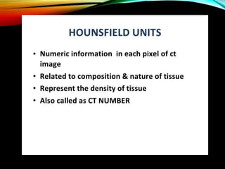
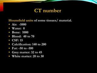
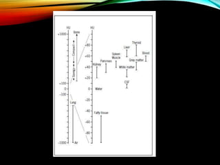
1) The linear attenuation coefficient describes how much a beam of radiation is absorbed or scattered as it passes through a medium. CT numbers represent differences from the linear attenuation coefficient of water.
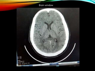
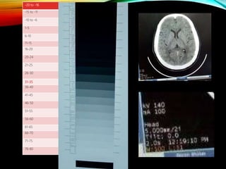
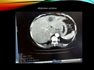
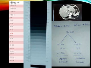
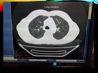
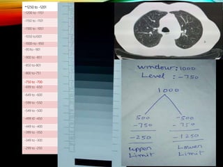
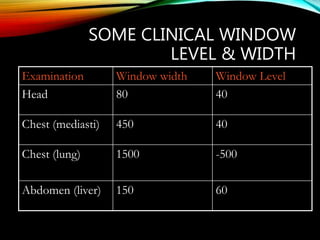
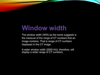
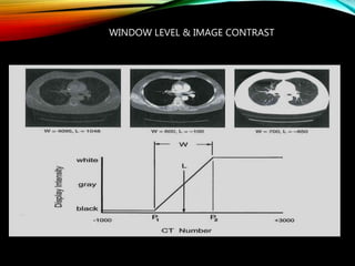
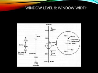
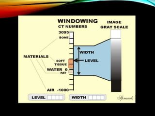
2) Window width determines the range and contrast of CT numbers displayed. A narrow width provides higher contrast than a wide width.
3) Window level sets the midpoint brightness level of the displayed CT numbers. It controls the brightness of the CT image.