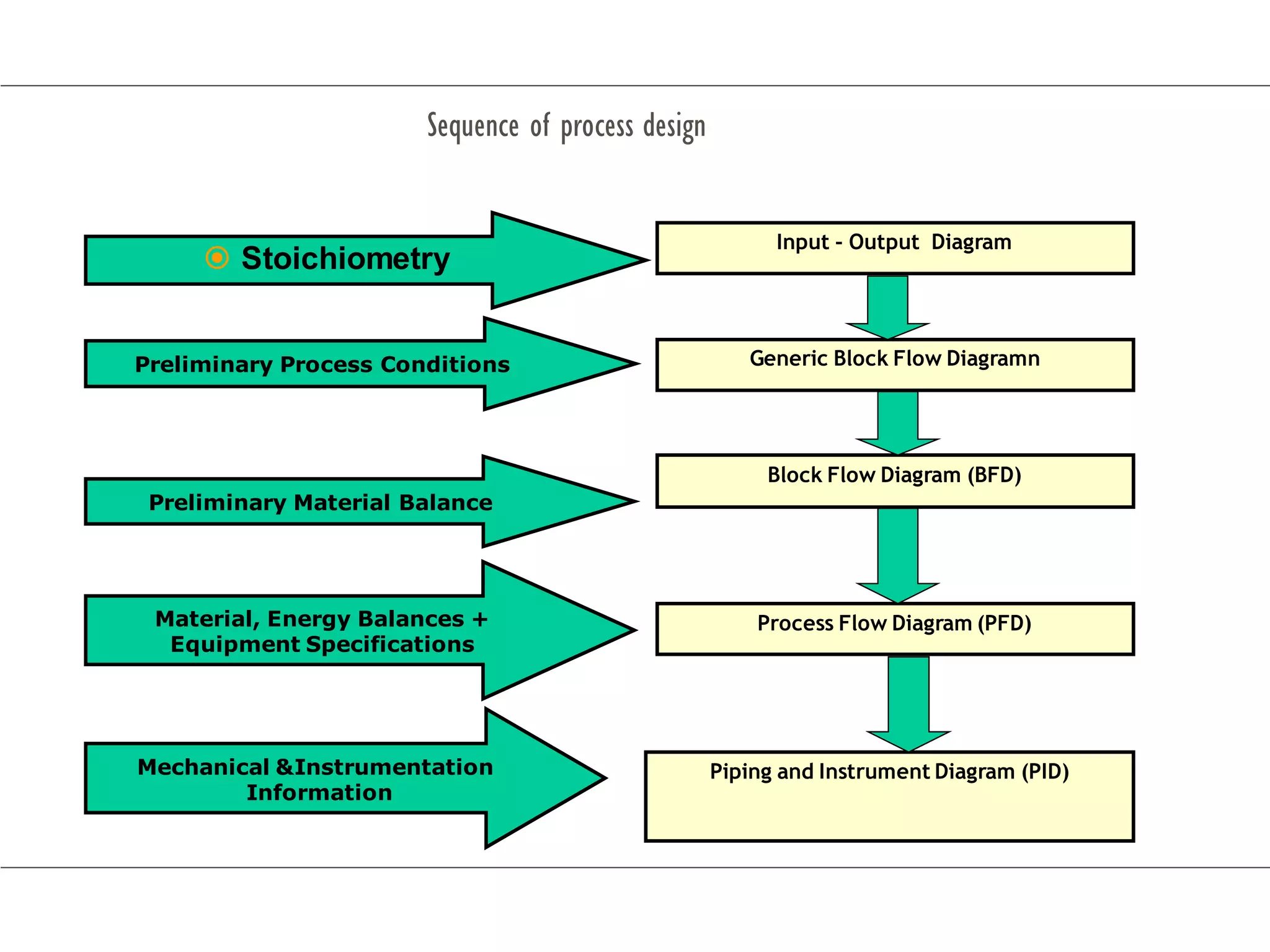
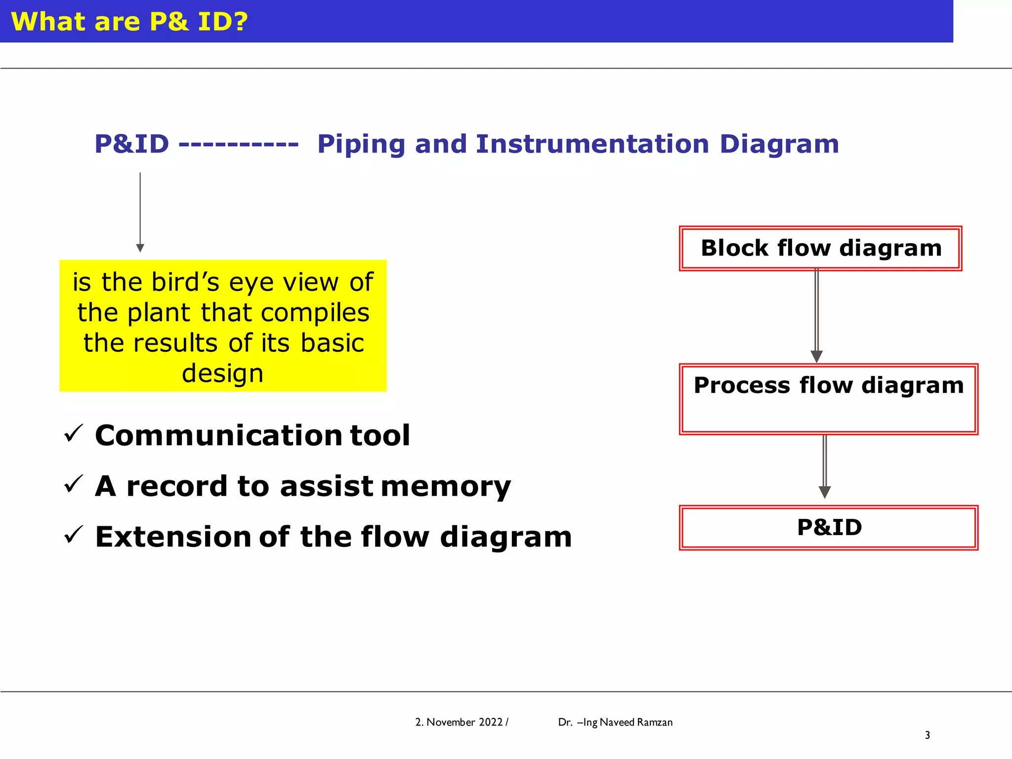
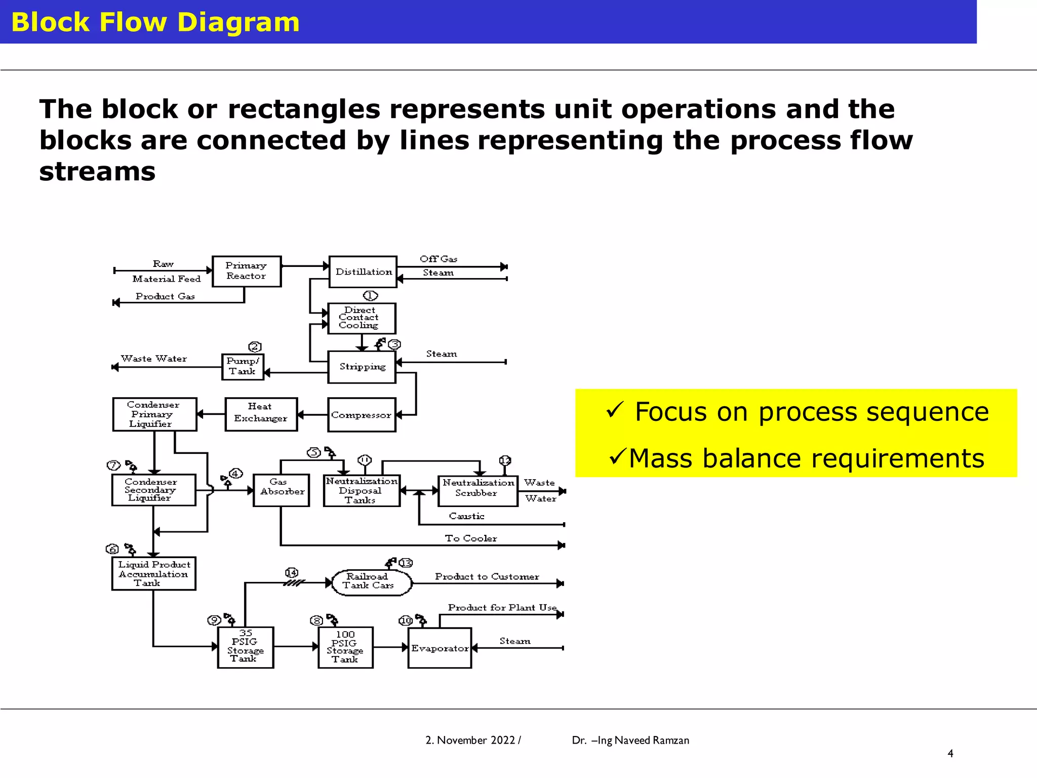
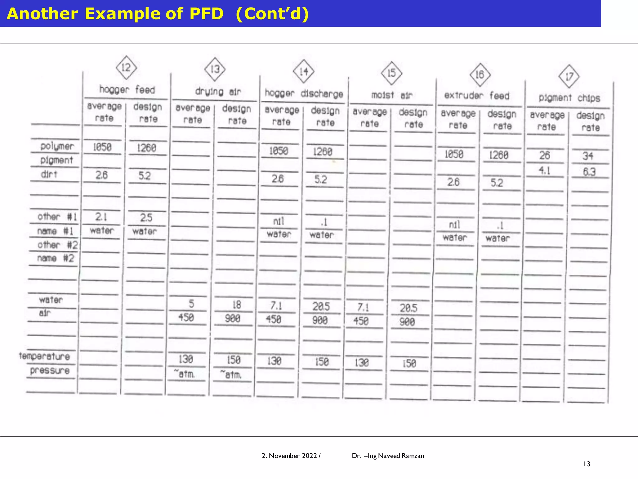
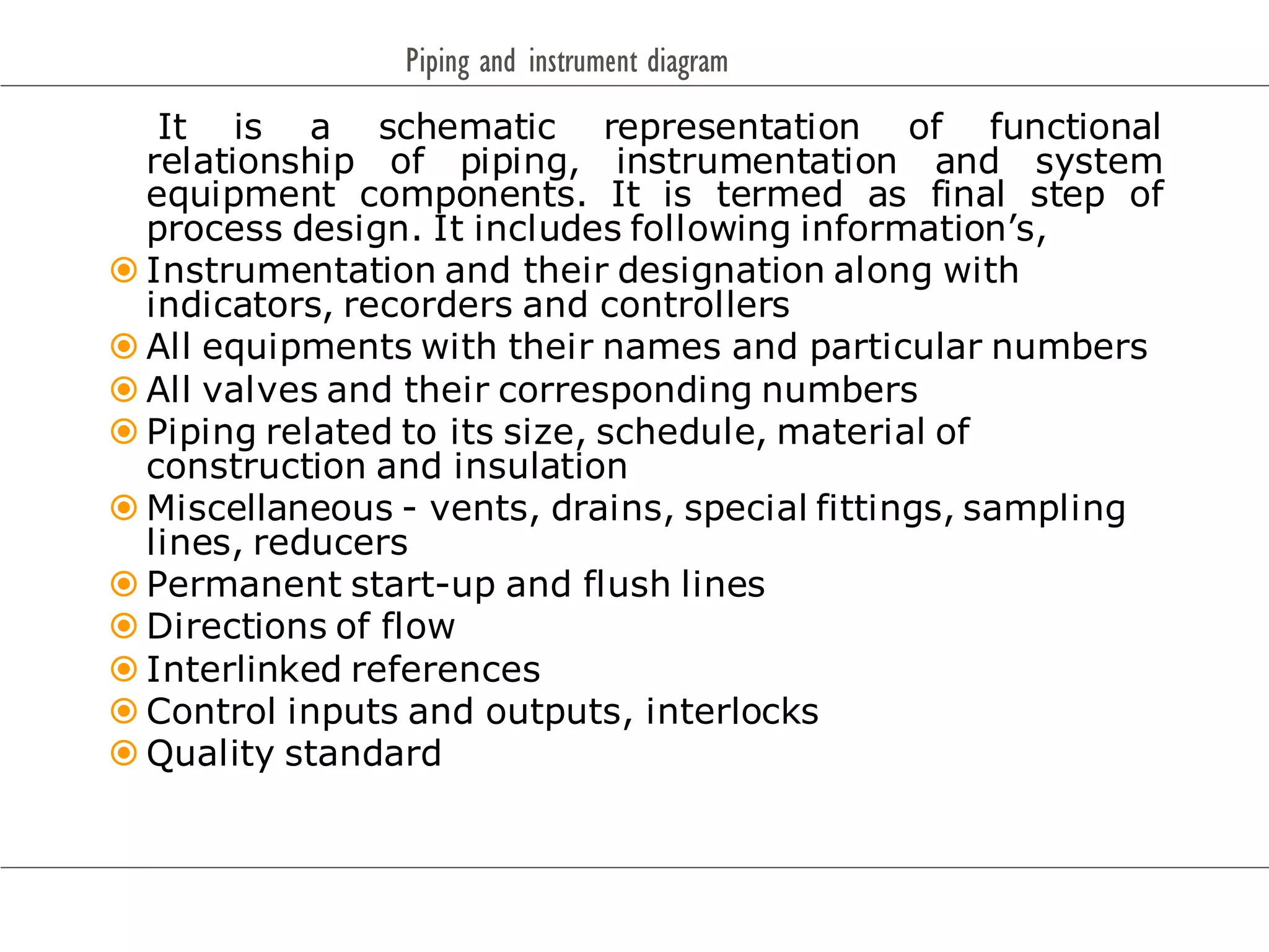
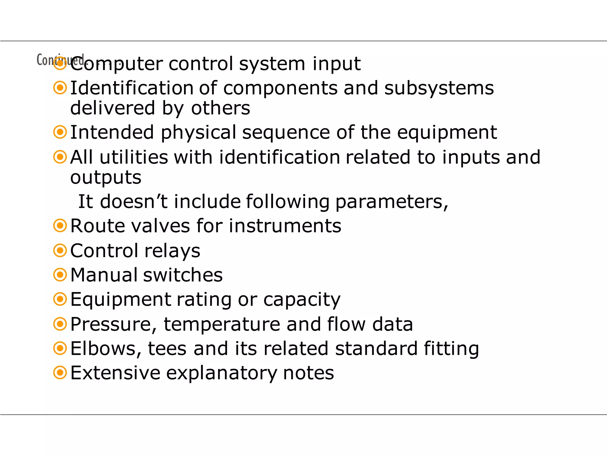
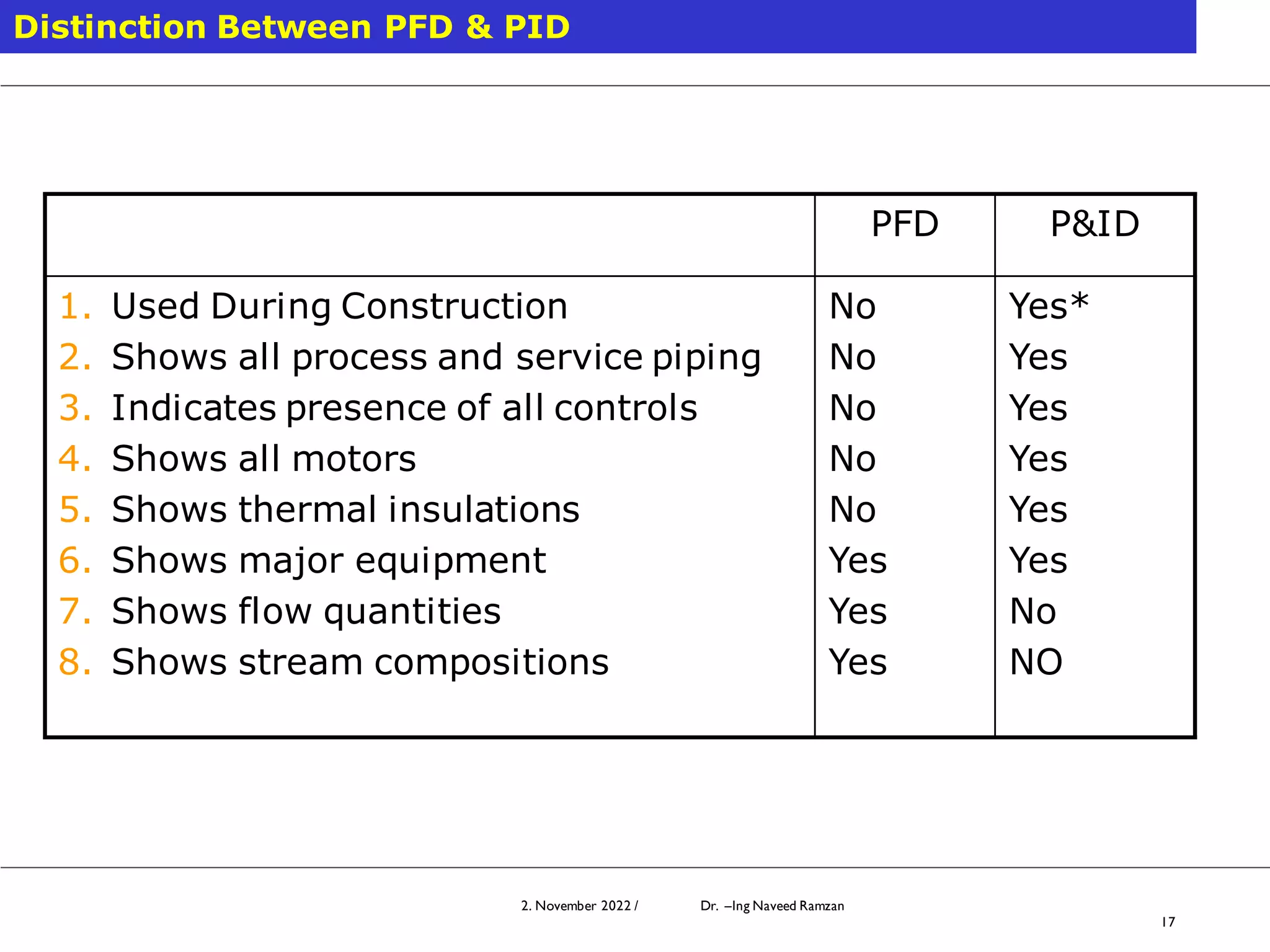
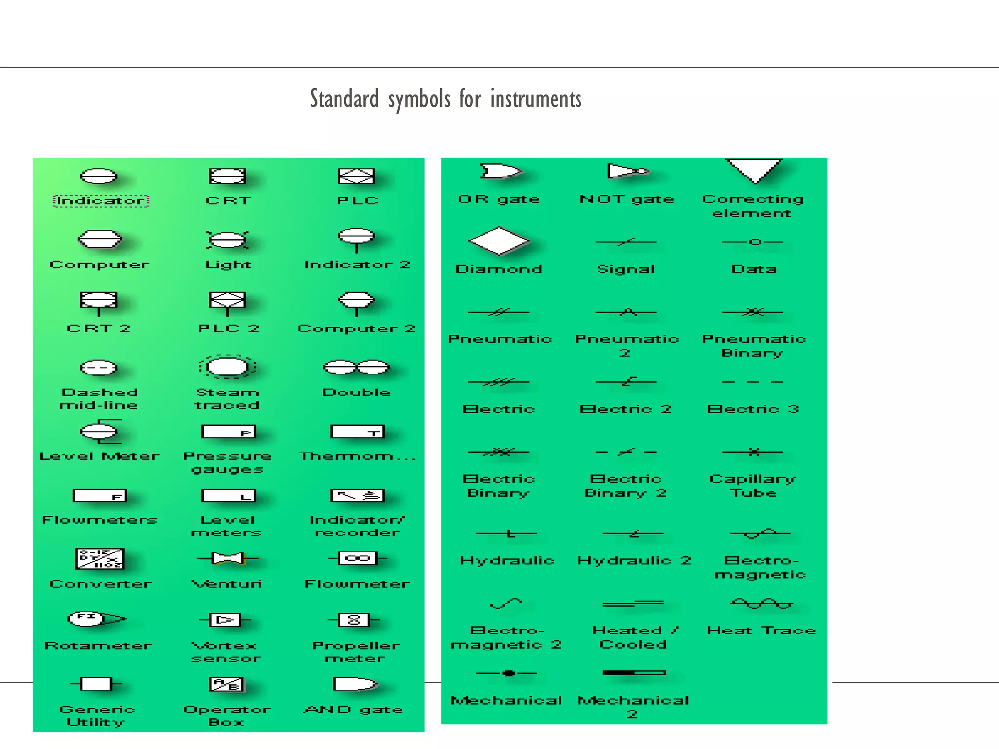
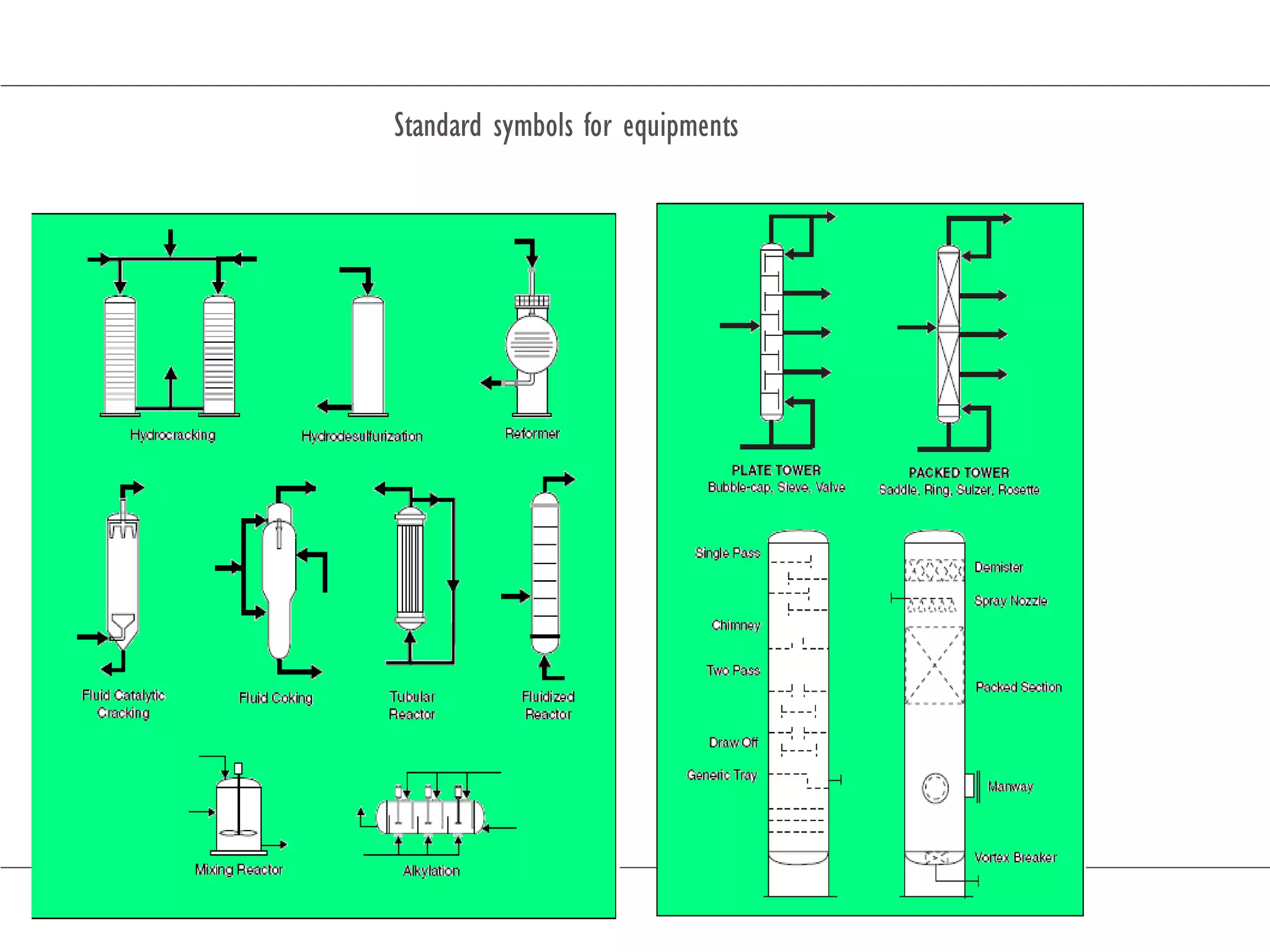
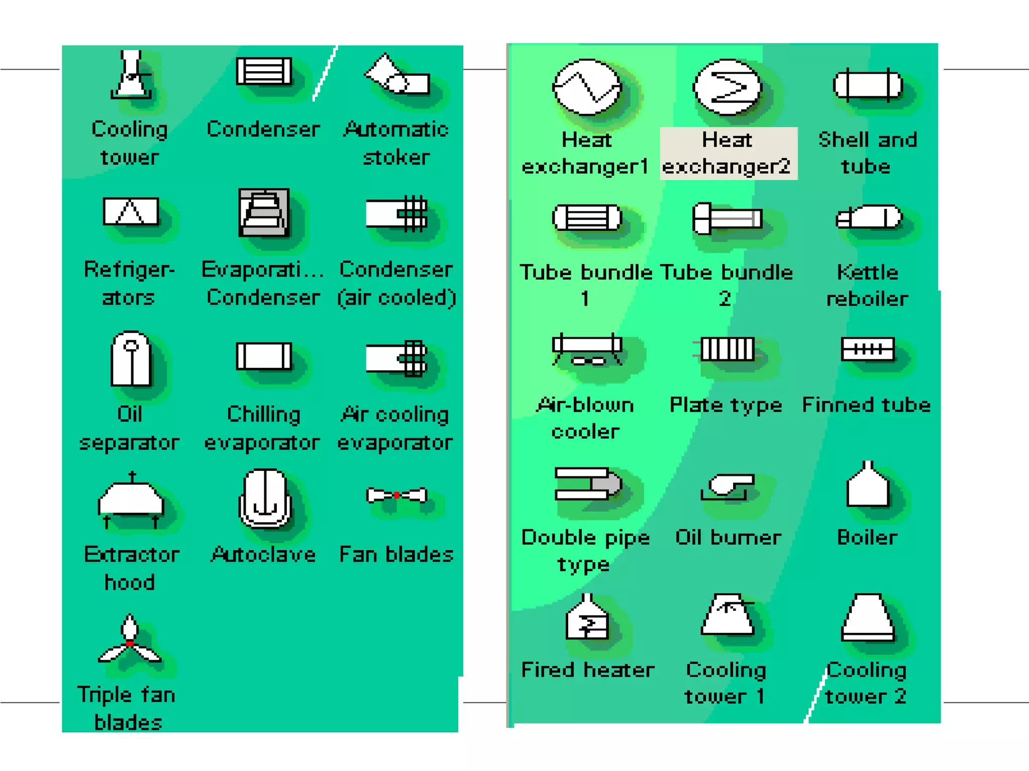
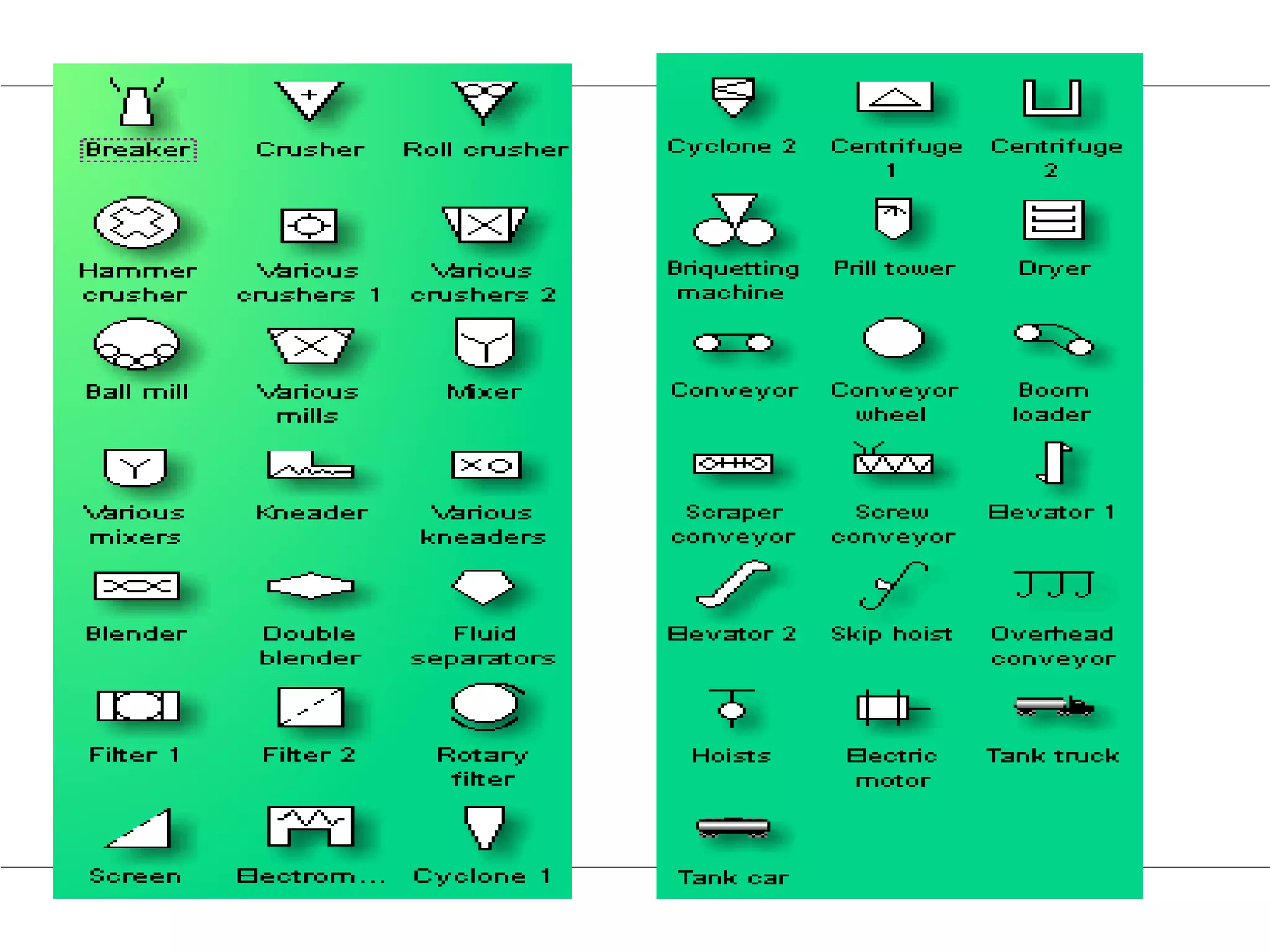
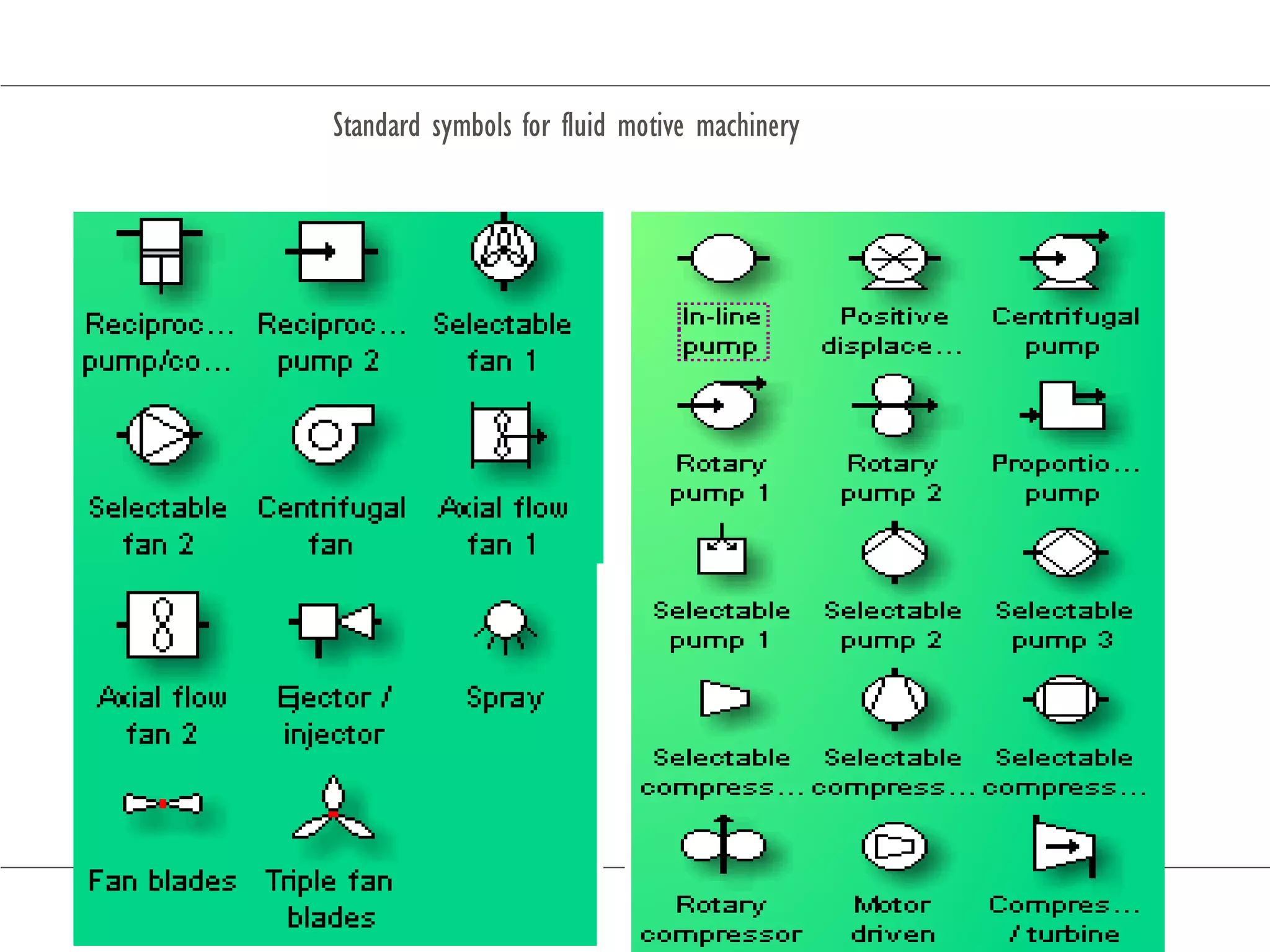
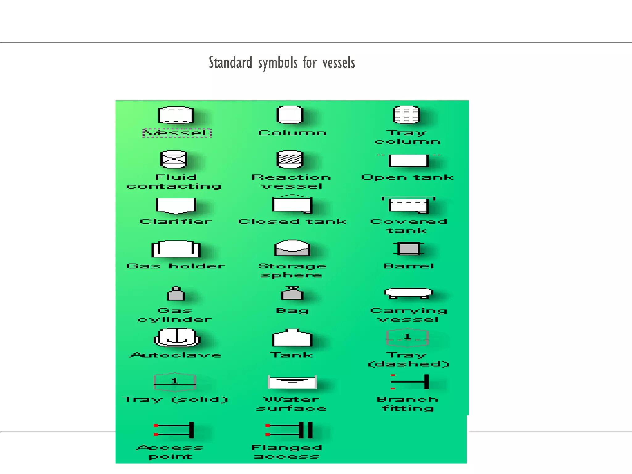
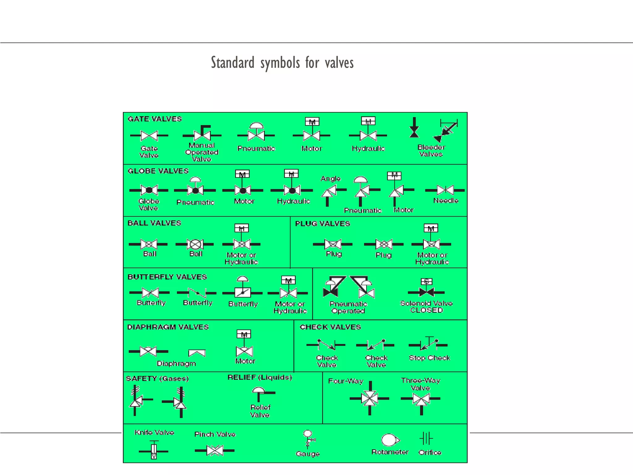
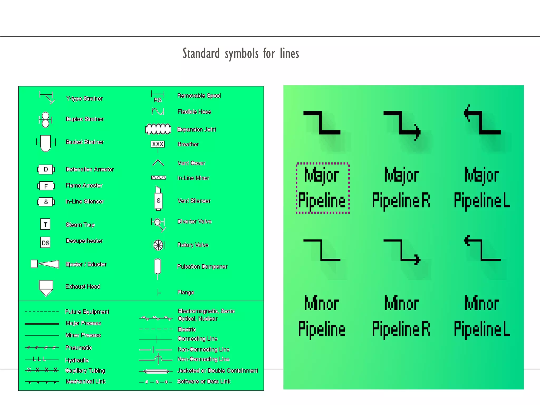
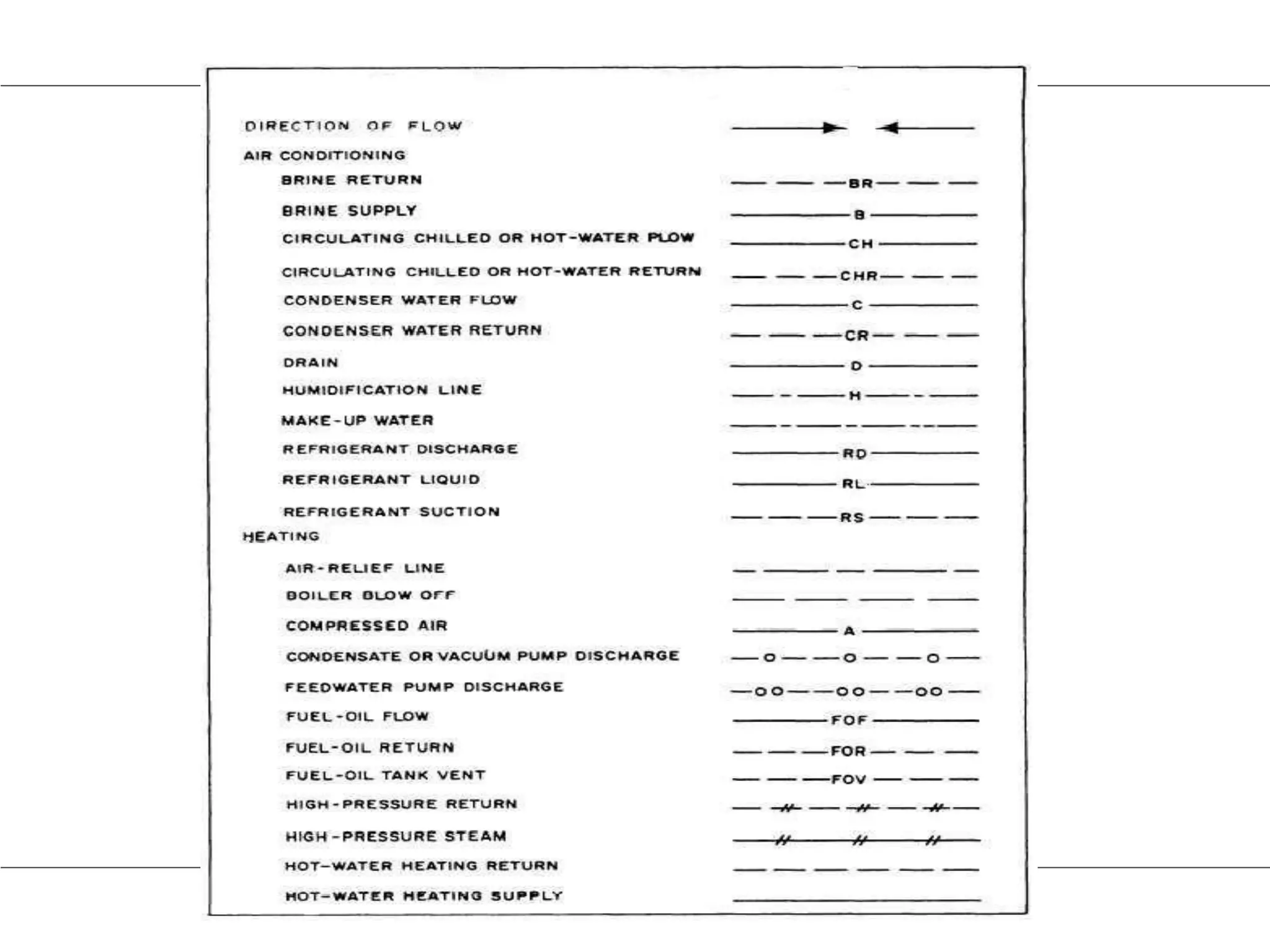
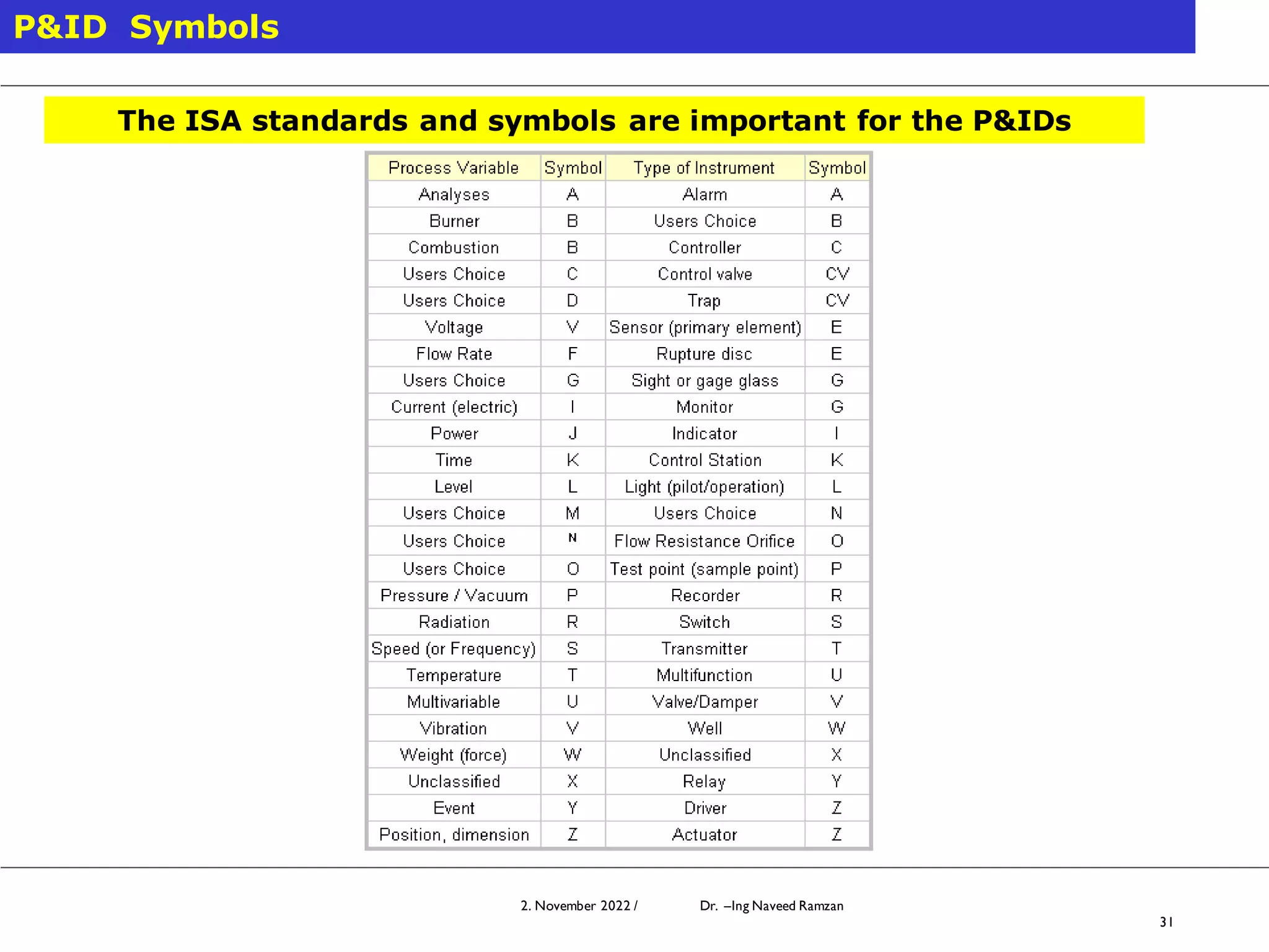
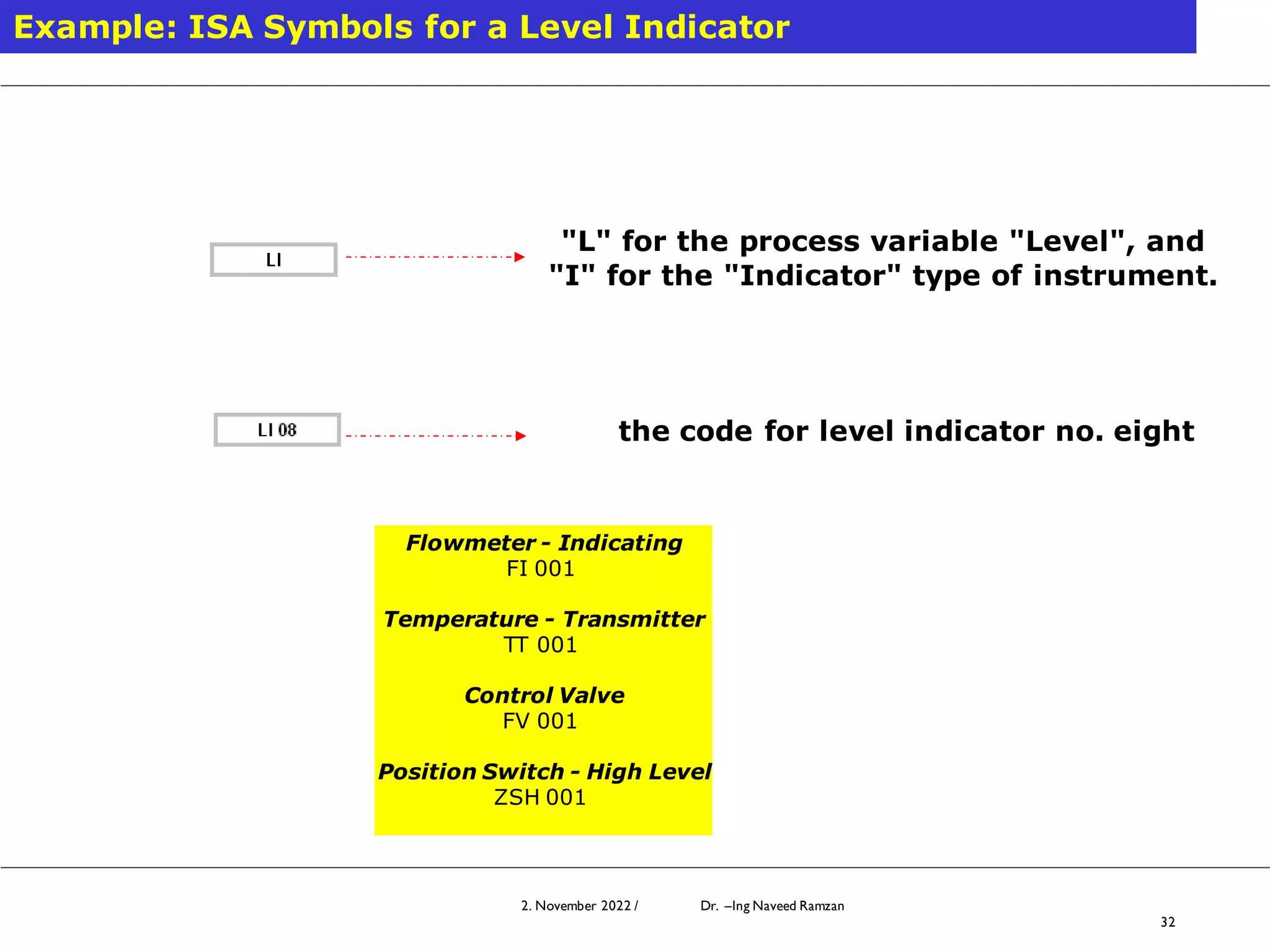
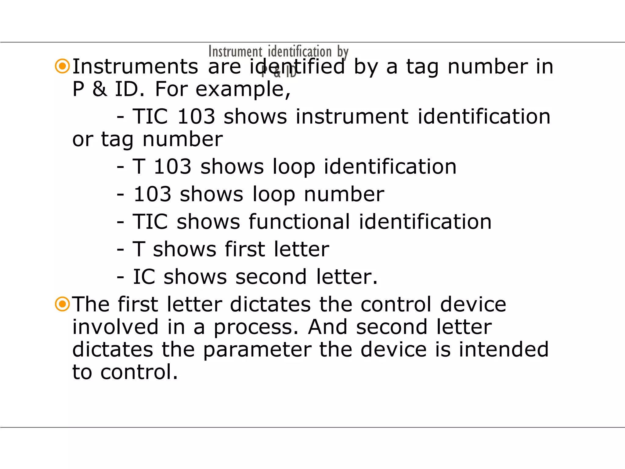
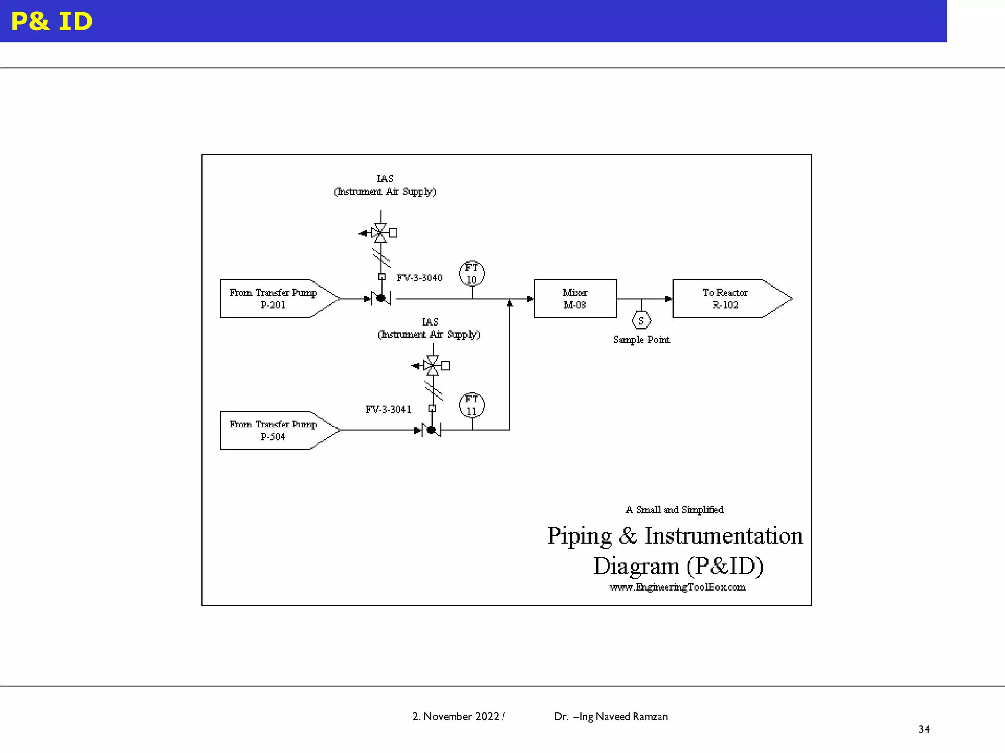
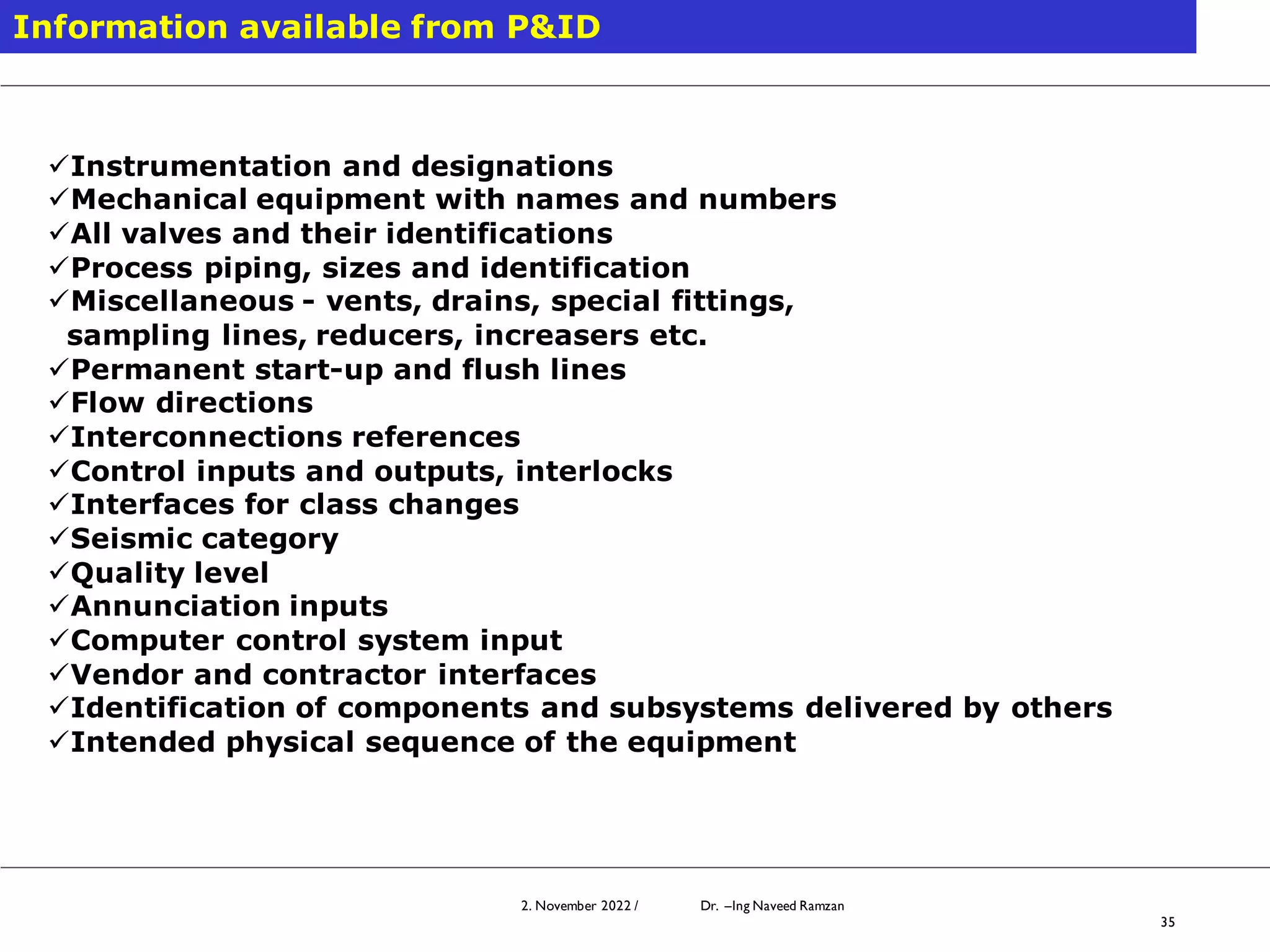
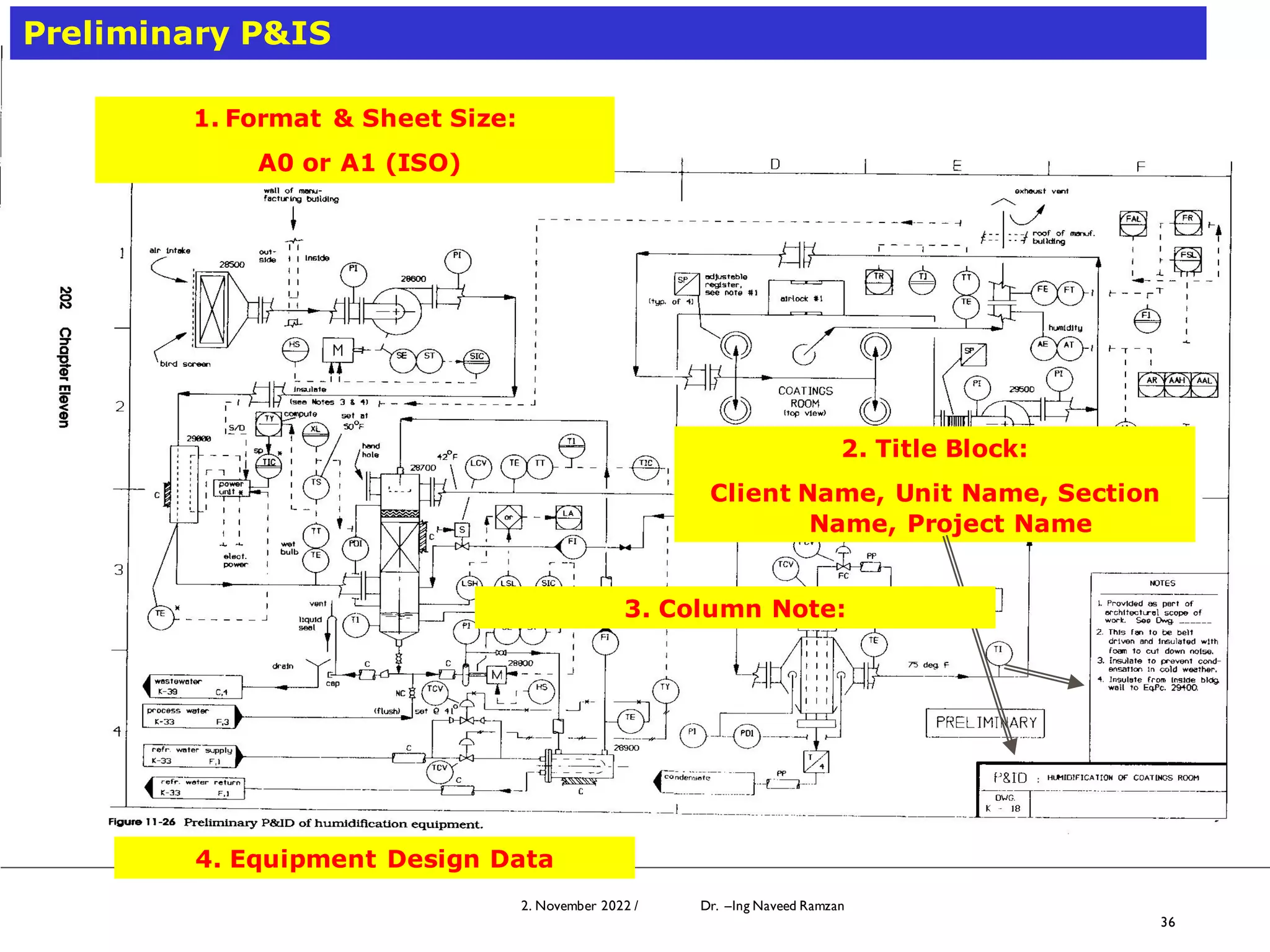
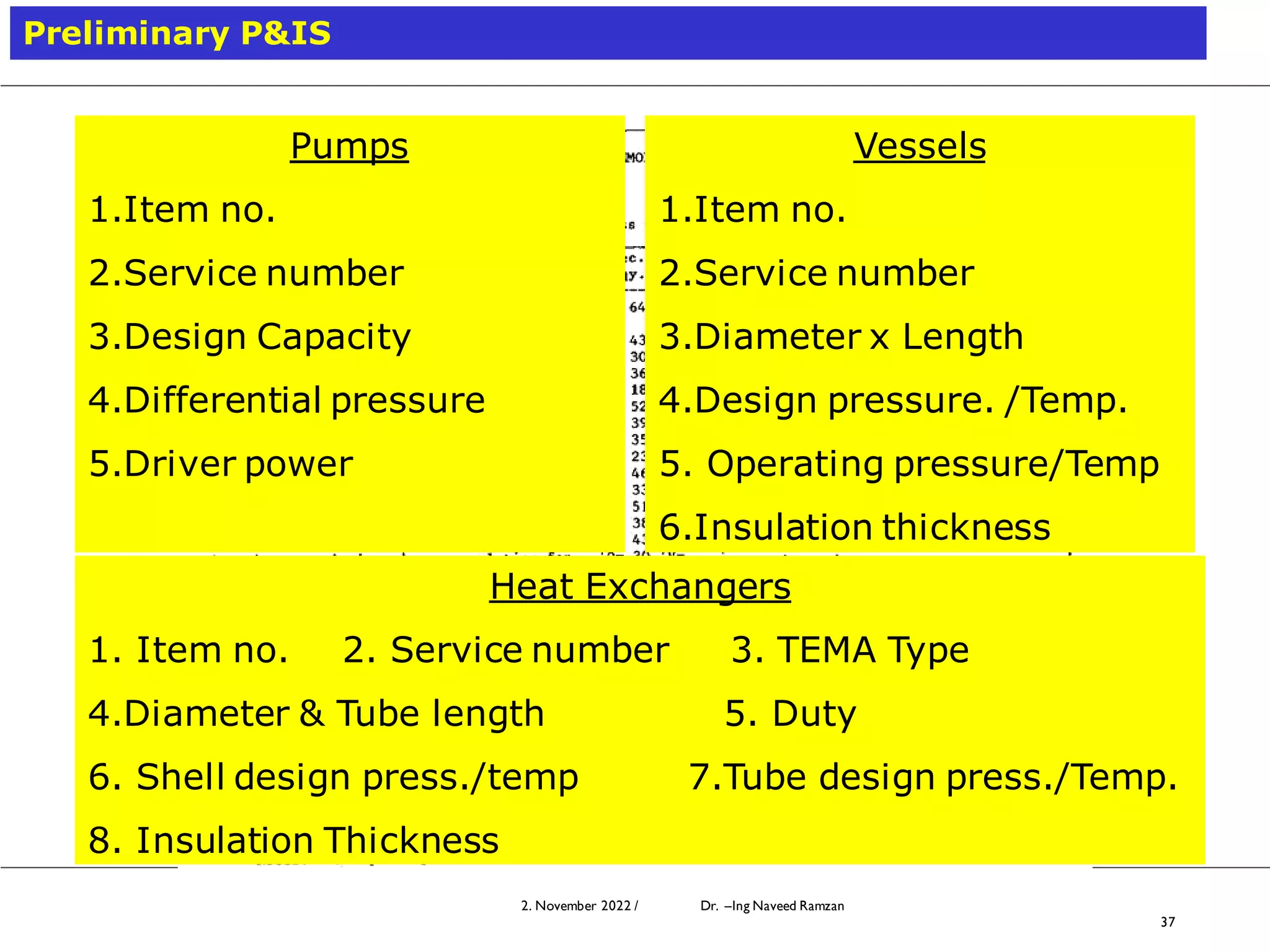
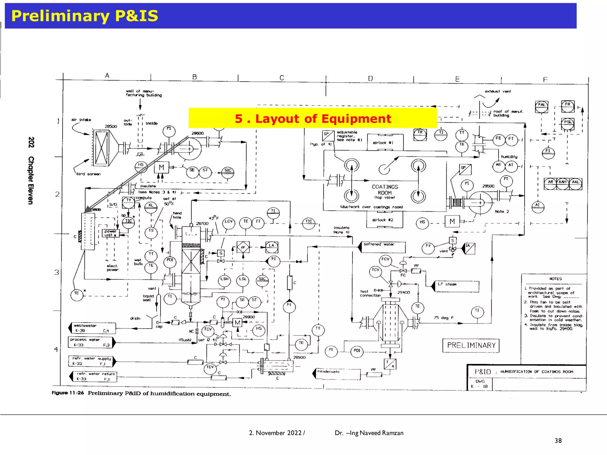
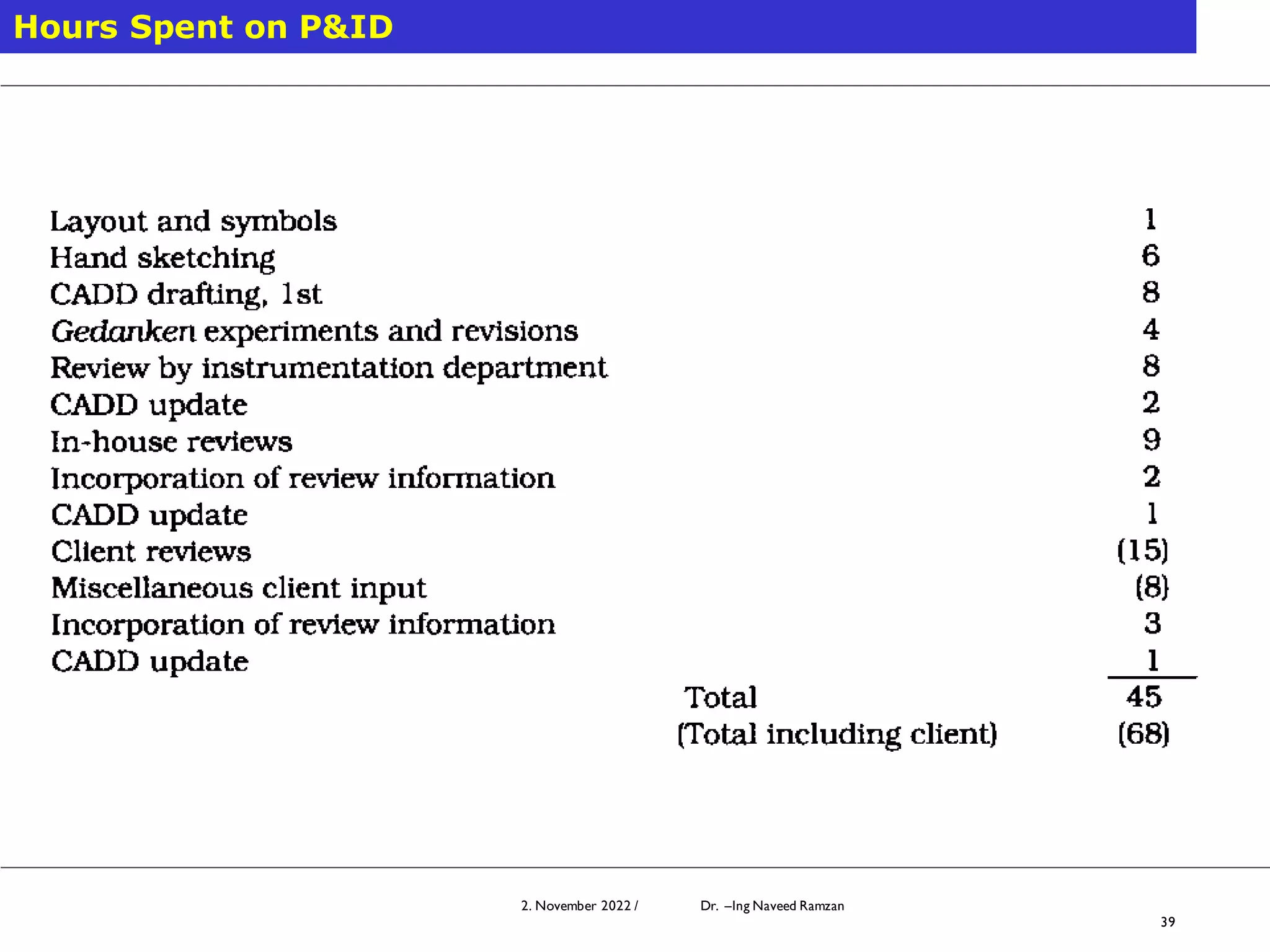
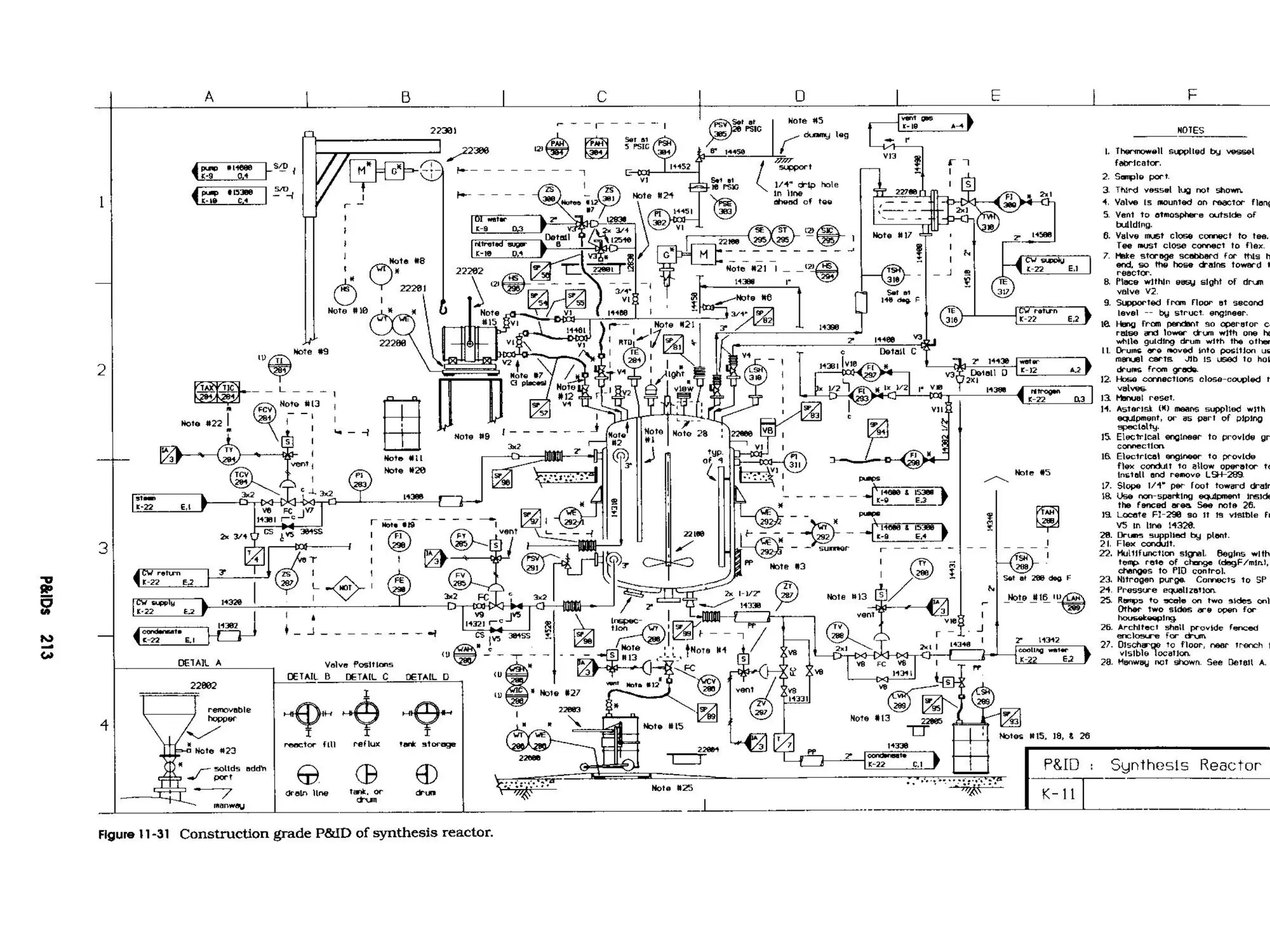
Modelling and Simulation 2. November 2022 / Dr. –Ing Naveed Ramzan
1
2. November 2022 / Dr. –Ing Naveed Ramzan
1
Instrumentation and control
Department of Chemical Engineering, U.E.T. Lahore Pakistan
Dr. –Ing. Naveed Ramzan
Piping & Instrumentation Diagram
P&ID
Sequence of process design
 Stoichiometry
Preliminary Process Conditions
Preliminary Material Balance
Material, Energy Balances +
Equipment Specifications
Mechanical &Instrumentation
Information
Input - Output Diagram
Generic Block Flow Diagramn
Block Flow Diagram (BFD)
Process Flow Diagram (PFD)
Piping and Instrument Diagram (PID)
2. November 2022 / Dr. –Ing Naveed Ramzan
3
What are P& ID?
P&ID ---------- Piping and Instrumentation Diagram
is the bird’s eye view of
the plant that compiles
the results of its basic
design
✓ Communication tool
✓ A record to assist memory
✓ Extension of the flow diagram
Block flow diagram
Process flow diagram
P&ID
2. November 2022 / Dr. –Ing Naveed Ramzan
4
Block Flow Diagram
The block or rectangles represents unit operations and the
blocks are connected by lines representing the process flow
streams
✓ Focus on process sequence
✓Mass balance requirements
Block flow diagram
It consists of simple block elements that are
connected with an arrow. It describes following
information’s,
o Each block represents a process function which in
reality may consist of several pieces of equipment.
o Gives a clear overview uncluttered by details.
o Effective for conceptualizing a new process or a
PFD.
o Major flow lines shown with arrows giving direction
of flow.
o Flow goes from left to right whenever possible.
o Light streams (gases, vapors) move towards top
and heavy streams (solid, liquid) go towards
bottom.
o If lines cross each other then, horizontal line is
continuous and vertical line is broken.
o Provides preliminary material balance.
Air
Ammonia
Carbon Dioxide
Urea Prills
Ammonia
Unit
Urea
Unit
Bagging
&
Shipping
Utility
Unit
Fuel Gas Utility
Unit
2. November 2022 / Dr. –Ing Naveed Ramzan
7
Process Flow Diagram or Flow Sheet
✓ Relationships between the major components in the system
✓ Tabulate process design values for the components
Process flow diagram
It is a diagram of fluid flow system showing the
equipment items connected by major process pipes
and containing data on essential process control
circuits or major process requirements. It would
include following details.
Process piping
Major equipment names
Major equipment numbers
Major equipment identification numbers
Control valves
Interconnection with other system
Major bypass and circulation lines
System rating and operational values as maximum,
minimum and normal flow
Continued…….
Process parameters i.e. temperature and
pressure
Composition of fluids
A process flow diagram does not following
details,
Pipe class
Pipe line number
Maintenance vents and drains
Relief and safety valves
Code class information
Seismic class information
Instruments
2. November 2022 / Dr. –Ing Naveed Ramzan
10
Process Flow Diagram or Flow Sheet (Cont’d)
2. November 2022 / Dr. –Ing Naveed Ramzan
11
Process Flow Diagram or Flow Sheet (Cont’d)
Classic Symbols
Assignment:
A– Each team come up with symbols of other equipments
2. November 2022 / Dr. –Ing Naveed Ramzan
12
Another Example of PFD
2. November 2022 / Dr. –Ing Naveed Ramzan
13
Another Example of PFD (Cont’d)
2. November 2022 / Dr. –Ing Naveed Ramzan
14
Another Example of PFD (Cont’d)
Piping and instrument diagram
It is a schematic representation of functional
relationship of piping, instrumentation and system
equipment components. It is termed as final step of
process design. It includes following information’s,
 Instrumentation and their designation along with
indicators, recorders and controllers
 All equipments with their names and particular numbers
 All valves and their corresponding numbers
 Piping related to its size, schedule, material of
construction and insulation
 Miscellaneous - vents, drains, special fittings, sampling
lines, reducers
 Permanent start-up and flush lines
 Directions of flow
 Interlinked references
 Control inputs and outputs, interlocks
 Quality standard
Continued…….
Computer control system input
Identification of components and subsystems
delivered by others
Intended physical sequence of the equipment
All utilities with identification related to inputs and
outputs
It doesn’t include following parameters,
Route valves for instruments
Control relays
Manual switches
Equipment rating or capacity
Pressure, temperature and flow data
Elbows, tees and its related standard fitting
Extensive explanatory notes
2. November 2022 / Dr. –Ing Naveed Ramzan
17
Distinction Between PFD & PID
PFD P&ID
1. Used During Construction
2. Shows all process and service piping
3. Indicates presence of all controls
4. Shows all motors
5. Shows thermal insulations
6. Shows major equipment
7. Shows flow quantities
8. Shows stream compositions
No
No
No
No
No
Yes
Yes
Yes
Yes*
Yes
Yes
Yes
Yes
Yes
No
NO
2. November 2022 / Dr. –Ing Naveed Ramzan
18
P&ID
P&ID quality determines whether the projects succeeds or fails
Types of P&ID
✓P&ID for Individual Units
✓P&ID for Utility Distribution
✓P&ID for Interconnecting Pipe work
✓P&ID for Tie-in Connection
✓P&ID for Auxiliary facilties
✓P&ID for packaged units
Not all of the above P&IDs are always prepared in a project
Composing the onsite & offsite facilities
UFD ; flow of utilities in onsite facilities
Coordination flow diagram;
interconnection B/W units & offsite
,onsite facilities
Tie in points of new units with existing
Detailed information for equipments can
not be shown on P&ID for individual units
P& ID for units such as compressor,
refrigeration etc.
2. November 2022 / Dr. –Ing Naveed Ramzan
19
P&ID Symbols
Good symbols are essential to helping the reader of P&ID
2. November 2022 / Dr. –Ing Naveed Ramzan
20
P&ID Symbols
A symbol expresses or suggests an idea by standing for it
Assignment:
A– Come with as much symbols as you can
Winner who come with more symbols
Standard symbols for instruments
Standard symbols for equipments
Standard symbols for fluid motive machinery
Standard symbols for vessels
Standard symbols for valves
Standard symbols for lines
2. November 2022 / Dr. –Ing Naveed Ramzan
31
P&ID Symbols
The ISA standards and symbols are important for the P&IDs
2. November 2022 / Dr. –Ing Naveed Ramzan
32
Example: ISA Symbols for a Level Indicator
"L" for the process variable "Level", and
"I" for the "Indicator" type of instrument.
the code for level indicator no. eight
Flowmeter - Indicating
FI 001
Temperature - Transmitter
TT 001
Control Valve
FV 001
Position Switch - High Level
ZSH 001
Instrument identification by
P & ID
Instruments are identified by a tag number in
P & ID. For example,
- TIC 103 shows instrument identification
or tag number
- T 103 shows loop identification
- 103 shows loop number
- TIC shows functional identification
- T shows first letter
- IC shows second letter.
The first letter dictates the control device
involved in a process. And second letter
dictates the parameter the device is intended
to control.
2. November 2022 / Dr. –Ing Naveed Ramzan
34
P& ID
2. November 2022 / Dr. –Ing Naveed Ramzan
35
Information available from P&ID
✓Instrumentation and designations
✓Mechanical equipment with names and numbers
✓All valves and their identifications
✓Process piping, sizes and identification
✓Miscellaneous - vents, drains, special fittings,
sampling lines, reducers, increasers etc.
✓Permanent start-up and flush lines
✓Flow directions
✓Interconnections references
✓Control inputs and outputs, interlocks
✓Interfaces for class changes
✓Seismic category
✓Quality level
✓Annunciation inputs
✓Computer control system input
✓Vendor and contractor interfaces
✓Identification of components and subsystems delivered by others
✓Intended physical sequence of the equipment
2. November 2022 / Dr. –Ing Naveed Ramzan
36
Preliminary P&IS
1. Format & Sheet Size:
A0 or A1 (ISO)
2. Title Block:
Client Name, Unit Name, Section
Name, Project Name
3. Column Note:
4. Equipment Design Data
2. November 2022 / Dr. –Ing Naveed Ramzan
37
Preliminary P&IS
Pumps
1.Item no.
2.Service number
3.Design Capacity
4.Differential pressure
5.Driver power
Vessels
1.Item no.
2.Service number
3.Diameter x Length
4.Design pressure. /Temp.
5. Operating pressure/Temp
6.Insulation thickness
Heat Exchangers
1. Item no. 2. Service number 3. TEMA Type
4.Diameter & Tube length 5. Duty
6. Shell design press./temp 7.Tube design press./Temp.
8. Insulation Thickness
2. November 2022 / Dr. –Ing Naveed Ramzan
38
Preliminary P&IS
5 . Layout of Equipment
2. November 2022 / Dr. –Ing Naveed Ramzan
39
Hours Spent on P&ID
2. November 2022 / Dr. –Ing Naveed Ramzan
40
Modelling and Simulation 2. November 2022 / Dr. –Ing Naveed Ramzan
41
2. November 2022 / Dr. –Ing Naveed Ramzan
41

PIPING AND INSTRUMENTATION DIAGRAMS PRESENTATION.pdf

  • 1.
    Modelling and Simulation2. November 2022 / Dr. –Ing Naveed Ramzan 1 2. November 2022 / Dr. –Ing Naveed Ramzan 1 Instrumentation and control Department of Chemical Engineering, U.E.T. Lahore Pakistan Dr. –Ing. Naveed Ramzan Piping & Instrumentation Diagram P&ID
  • 2.
    Sequence of processdesign  Stoichiometry Preliminary Process Conditions Preliminary Material Balance Material, Energy Balances + Equipment Specifications Mechanical &Instrumentation Information Input - Output Diagram Generic Block Flow Diagramn Block Flow Diagram (BFD) Process Flow Diagram (PFD) Piping and Instrument Diagram (PID)
  • 3.
    2. November 2022/ Dr. –Ing Naveed Ramzan 3 What are P& ID? P&ID ---------- Piping and Instrumentation Diagram is the bird’s eye view of the plant that compiles the results of its basic design ✓ Communication tool ✓ A record to assist memory ✓ Extension of the flow diagram Block flow diagram Process flow diagram P&ID
  • 4.
    2. November 2022/ Dr. –Ing Naveed Ramzan 4 Block Flow Diagram The block or rectangles represents unit operations and the blocks are connected by lines representing the process flow streams ✓ Focus on process sequence ✓Mass balance requirements
  • 5.
    Block flow diagram Itconsists of simple block elements that are connected with an arrow. It describes following information’s, o Each block represents a process function which in reality may consist of several pieces of equipment. o Gives a clear overview uncluttered by details. o Effective for conceptualizing a new process or a PFD. o Major flow lines shown with arrows giving direction of flow. o Flow goes from left to right whenever possible. o Light streams (gases, vapors) move towards top and heavy streams (solid, liquid) go towards bottom. o If lines cross each other then, horizontal line is continuous and vertical line is broken. o Provides preliminary material balance.
  • 6.
  • 7.
    2. November 2022/ Dr. –Ing Naveed Ramzan 7 Process Flow Diagram or Flow Sheet ✓ Relationships between the major components in the system ✓ Tabulate process design values for the components
  • 8.
    Process flow diagram Itis a diagram of fluid flow system showing the equipment items connected by major process pipes and containing data on essential process control circuits or major process requirements. It would include following details. Process piping Major equipment names Major equipment numbers Major equipment identification numbers Control valves Interconnection with other system Major bypass and circulation lines System rating and operational values as maximum, minimum and normal flow
  • 9.
    Continued……. Process parameters i.e.temperature and pressure Composition of fluids A process flow diagram does not following details, Pipe class Pipe line number Maintenance vents and drains Relief and safety valves Code class information Seismic class information Instruments
  • 10.
    2. November 2022/ Dr. –Ing Naveed Ramzan 10 Process Flow Diagram or Flow Sheet (Cont’d)
  • 11.
    2. November 2022/ Dr. –Ing Naveed Ramzan 11 Process Flow Diagram or Flow Sheet (Cont’d) Classic Symbols Assignment: A– Each team come up with symbols of other equipments
  • 12.
    2. November 2022/ Dr. –Ing Naveed Ramzan 12 Another Example of PFD
  • 13.
    2. November 2022/ Dr. –Ing Naveed Ramzan 13 Another Example of PFD (Cont’d)
  • 14.
    2. November 2022/ Dr. –Ing Naveed Ramzan 14 Another Example of PFD (Cont’d)
  • 15.
    Piping and instrumentdiagram It is a schematic representation of functional relationship of piping, instrumentation and system equipment components. It is termed as final step of process design. It includes following information’s,  Instrumentation and their designation along with indicators, recorders and controllers  All equipments with their names and particular numbers  All valves and their corresponding numbers  Piping related to its size, schedule, material of construction and insulation  Miscellaneous - vents, drains, special fittings, sampling lines, reducers  Permanent start-up and flush lines  Directions of flow  Interlinked references  Control inputs and outputs, interlocks  Quality standard
  • 16.
    Continued……. Computer control systeminput Identification of components and subsystems delivered by others Intended physical sequence of the equipment All utilities with identification related to inputs and outputs It doesn’t include following parameters, Route valves for instruments Control relays Manual switches Equipment rating or capacity Pressure, temperature and flow data Elbows, tees and its related standard fitting Extensive explanatory notes
  • 17.
    2. November 2022/ Dr. –Ing Naveed Ramzan 17 Distinction Between PFD & PID PFD P&ID 1. Used During Construction 2. Shows all process and service piping 3. Indicates presence of all controls 4. Shows all motors 5. Shows thermal insulations 6. Shows major equipment 7. Shows flow quantities 8. Shows stream compositions No No No No No Yes Yes Yes Yes* Yes Yes Yes Yes Yes No NO
  • 18.
    2. November 2022/ Dr. –Ing Naveed Ramzan 18 P&ID P&ID quality determines whether the projects succeeds or fails Types of P&ID ✓P&ID for Individual Units ✓P&ID for Utility Distribution ✓P&ID for Interconnecting Pipe work ✓P&ID for Tie-in Connection ✓P&ID for Auxiliary facilties ✓P&ID for packaged units Not all of the above P&IDs are always prepared in a project Composing the onsite & offsite facilities UFD ; flow of utilities in onsite facilities Coordination flow diagram; interconnection B/W units & offsite ,onsite facilities Tie in points of new units with existing Detailed information for equipments can not be shown on P&ID for individual units P& ID for units such as compressor, refrigeration etc.
  • 19.
    2. November 2022/ Dr. –Ing Naveed Ramzan 19 P&ID Symbols Good symbols are essential to helping the reader of P&ID
  • 20.
    2. November 2022/ Dr. –Ing Naveed Ramzan 20 P&ID Symbols A symbol expresses or suggests an idea by standing for it Assignment: A– Come with as much symbols as you can Winner who come with more symbols
  • 22.
  • 23.
  • 26.
    Standard symbols forfluid motive machinery
  • 27.
  • 28.
  • 29.
  • 31.
    2. November 2022/ Dr. –Ing Naveed Ramzan 31 P&ID Symbols The ISA standards and symbols are important for the P&IDs
  • 32.
    2. November 2022/ Dr. –Ing Naveed Ramzan 32 Example: ISA Symbols for a Level Indicator "L" for the process variable "Level", and "I" for the "Indicator" type of instrument. the code for level indicator no. eight Flowmeter - Indicating FI 001 Temperature - Transmitter TT 001 Control Valve FV 001 Position Switch - High Level ZSH 001
  • 33.
    Instrument identification by P& ID Instruments are identified by a tag number in P & ID. For example, - TIC 103 shows instrument identification or tag number - T 103 shows loop identification - 103 shows loop number - TIC shows functional identification - T shows first letter - IC shows second letter. The first letter dictates the control device involved in a process. And second letter dictates the parameter the device is intended to control.
  • 34.
    2. November 2022/ Dr. –Ing Naveed Ramzan 34 P& ID
  • 35.
    2. November 2022/ Dr. –Ing Naveed Ramzan 35 Information available from P&ID ✓Instrumentation and designations ✓Mechanical equipment with names and numbers ✓All valves and their identifications ✓Process piping, sizes and identification ✓Miscellaneous - vents, drains, special fittings, sampling lines, reducers, increasers etc. ✓Permanent start-up and flush lines ✓Flow directions ✓Interconnections references ✓Control inputs and outputs, interlocks ✓Interfaces for class changes ✓Seismic category ✓Quality level ✓Annunciation inputs ✓Computer control system input ✓Vendor and contractor interfaces ✓Identification of components and subsystems delivered by others ✓Intended physical sequence of the equipment
  • 36.
    2. November 2022/ Dr. –Ing Naveed Ramzan 36 Preliminary P&IS 1. Format & Sheet Size: A0 or A1 (ISO) 2. Title Block: Client Name, Unit Name, Section Name, Project Name 3. Column Note: 4. Equipment Design Data
  • 37.
    2. November 2022/ Dr. –Ing Naveed Ramzan 37 Preliminary P&IS Pumps 1.Item no. 2.Service number 3.Design Capacity 4.Differential pressure 5.Driver power Vessels 1.Item no. 2.Service number 3.Diameter x Length 4.Design pressure. /Temp. 5. Operating pressure/Temp 6.Insulation thickness Heat Exchangers 1. Item no. 2. Service number 3. TEMA Type 4.Diameter & Tube length 5. Duty 6. Shell design press./temp 7.Tube design press./Temp. 8. Insulation Thickness
  • 38.
    2. November 2022/ Dr. –Ing Naveed Ramzan 38 Preliminary P&IS 5 . Layout of Equipment
  • 39.
    2. November 2022/ Dr. –Ing Naveed Ramzan 39 Hours Spent on P&ID
  • 40.
    2. November 2022/ Dr. –Ing Naveed Ramzan 40
  • 41.
    Modelling and Simulation2. November 2022 / Dr. –Ing Naveed Ramzan 41 2. November 2022 / Dr. –Ing Naveed Ramzan 41