Downloaded 698 times
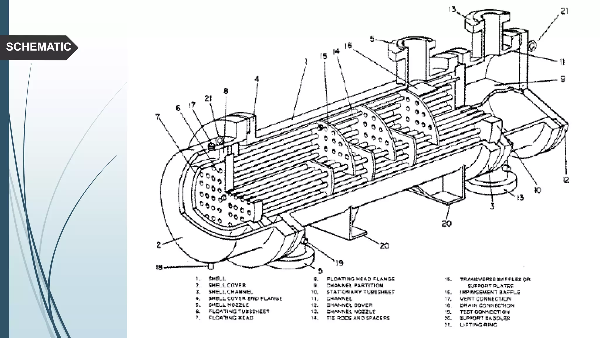
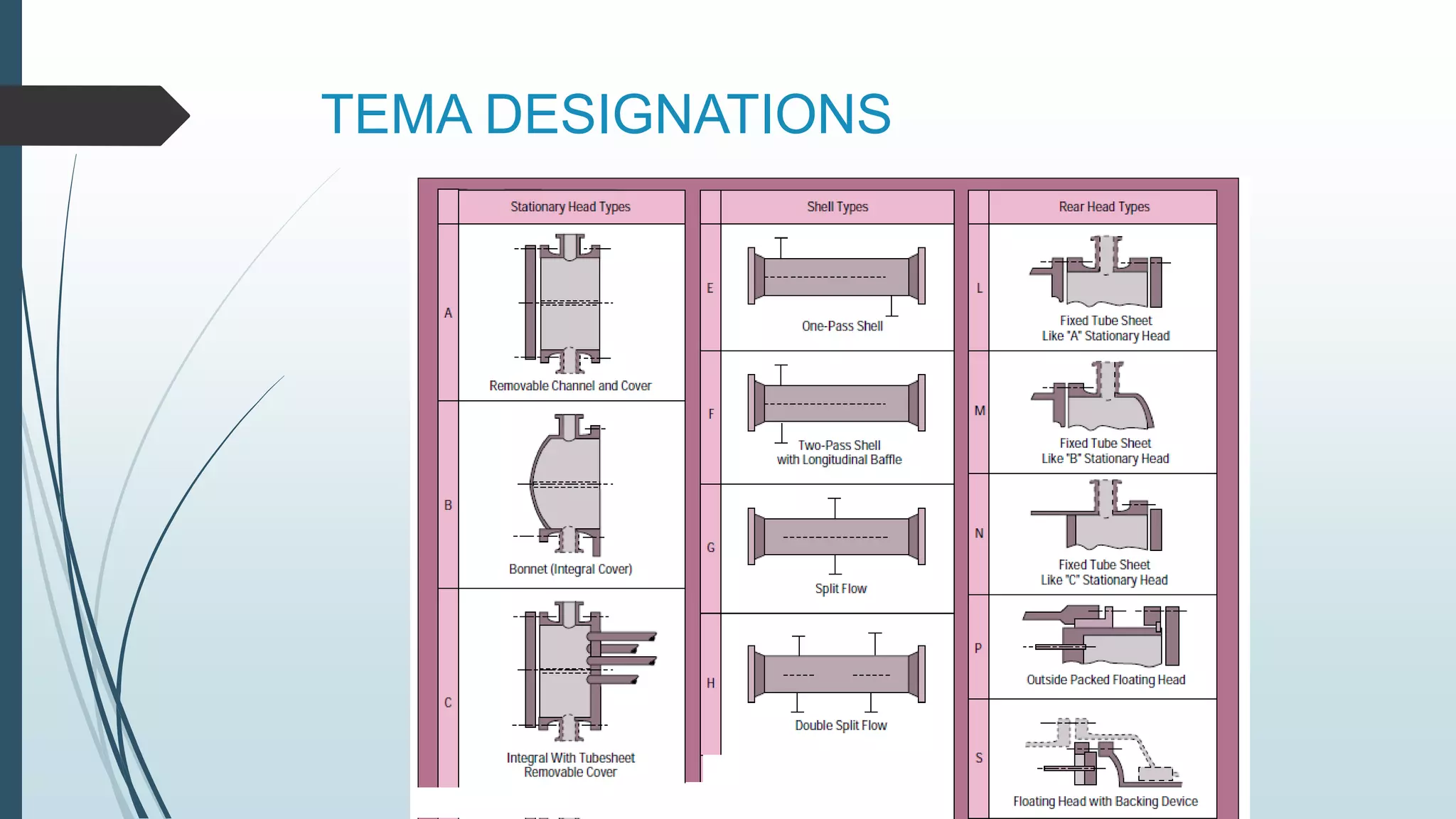
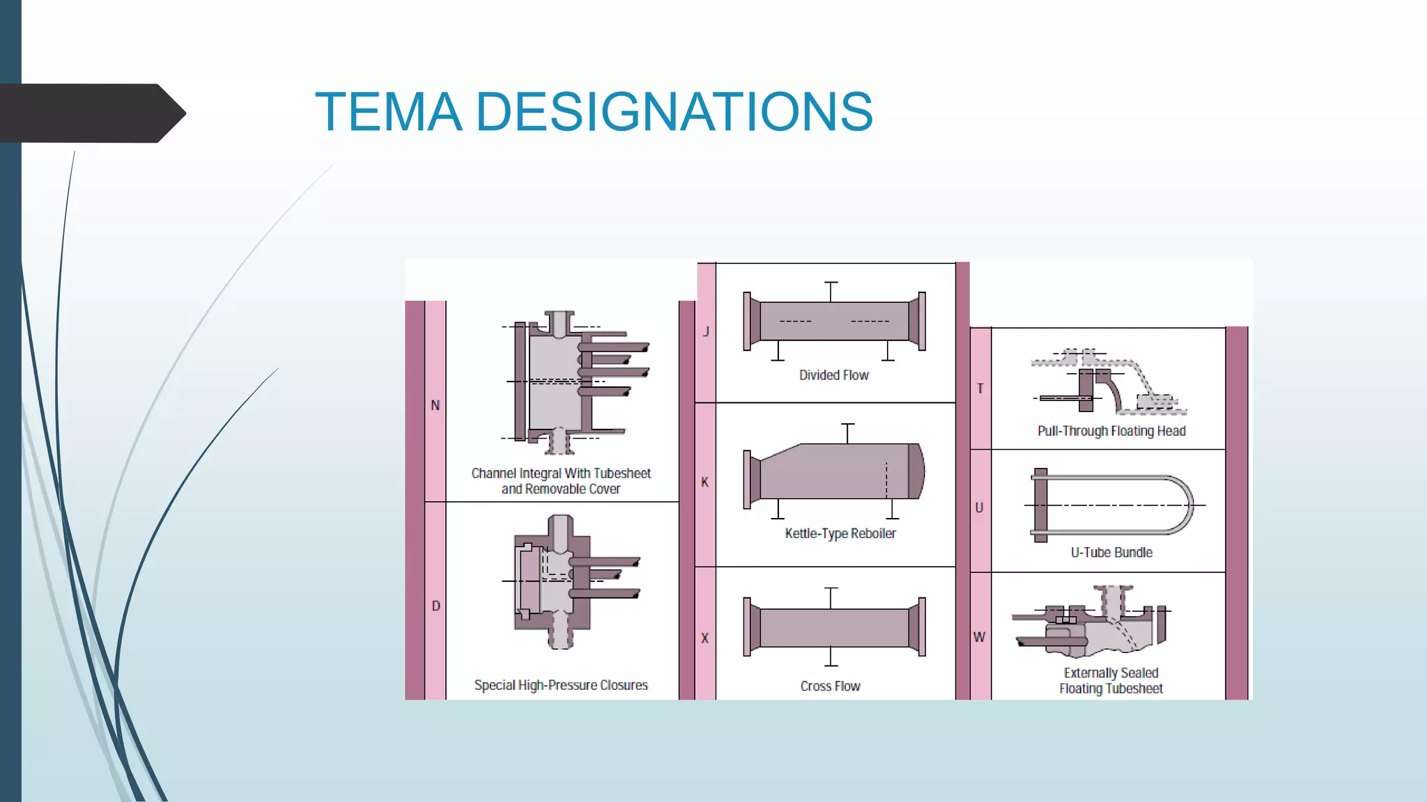
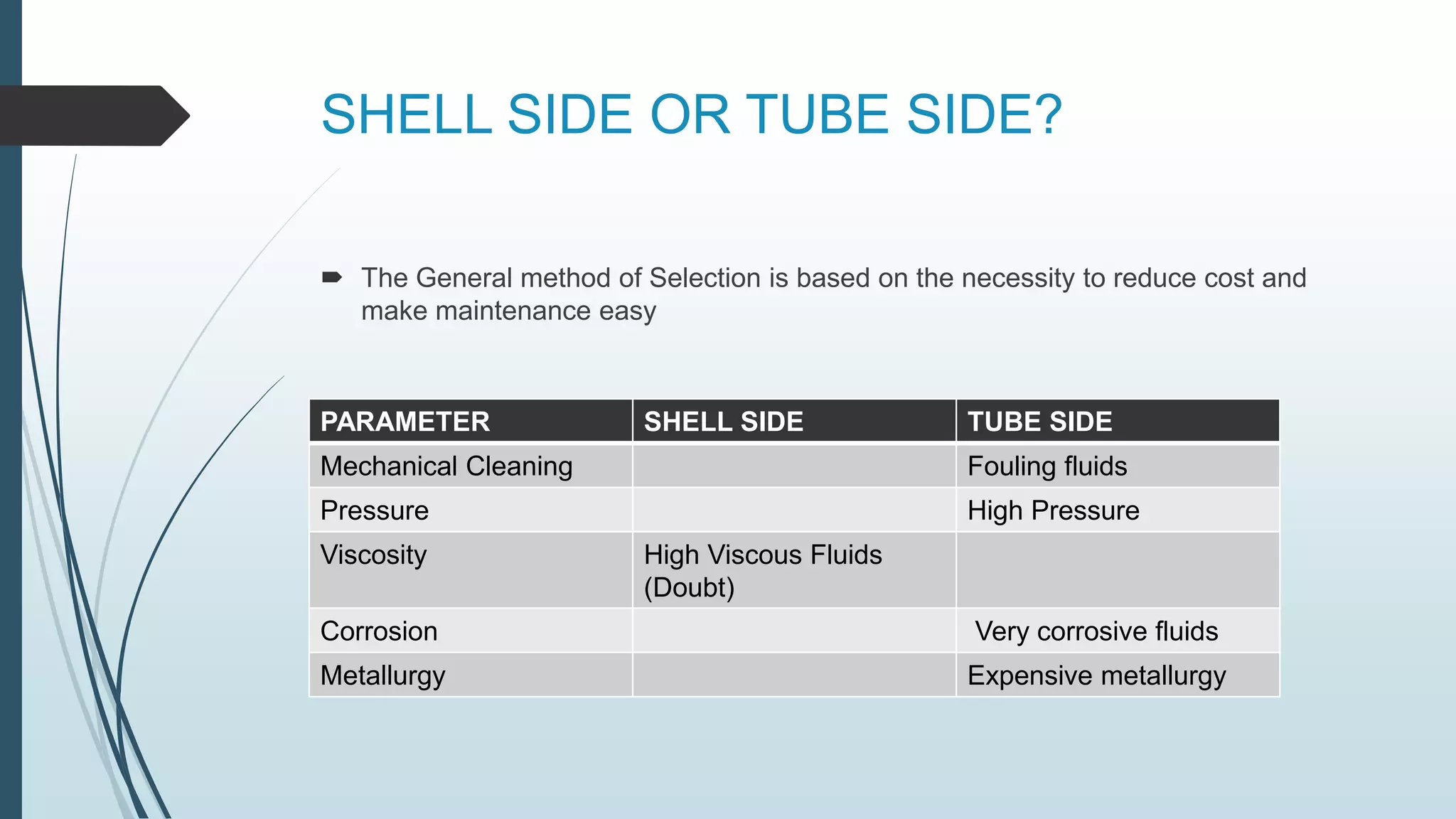
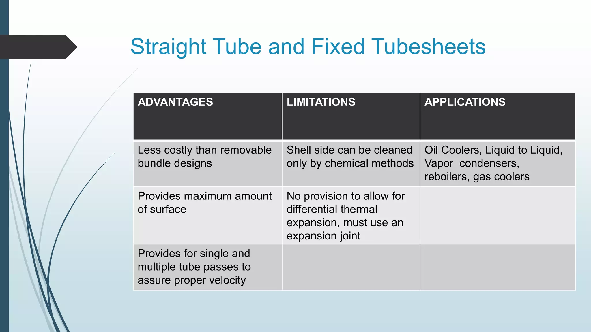
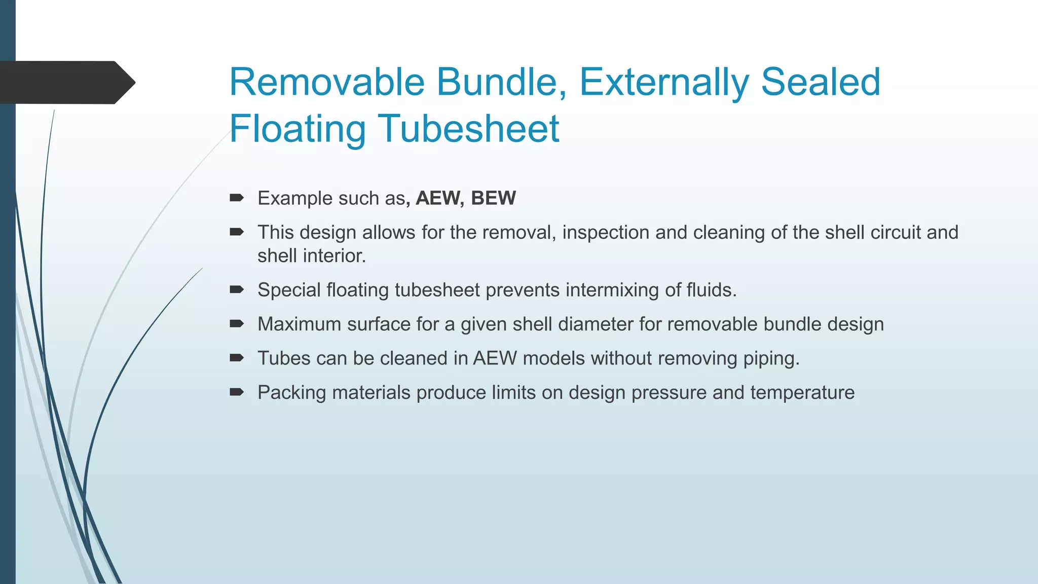
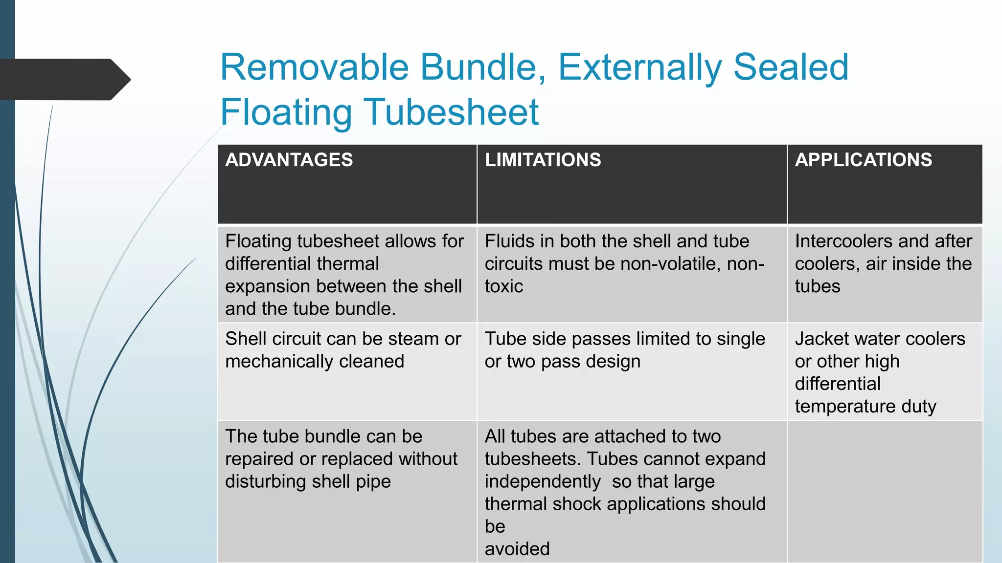
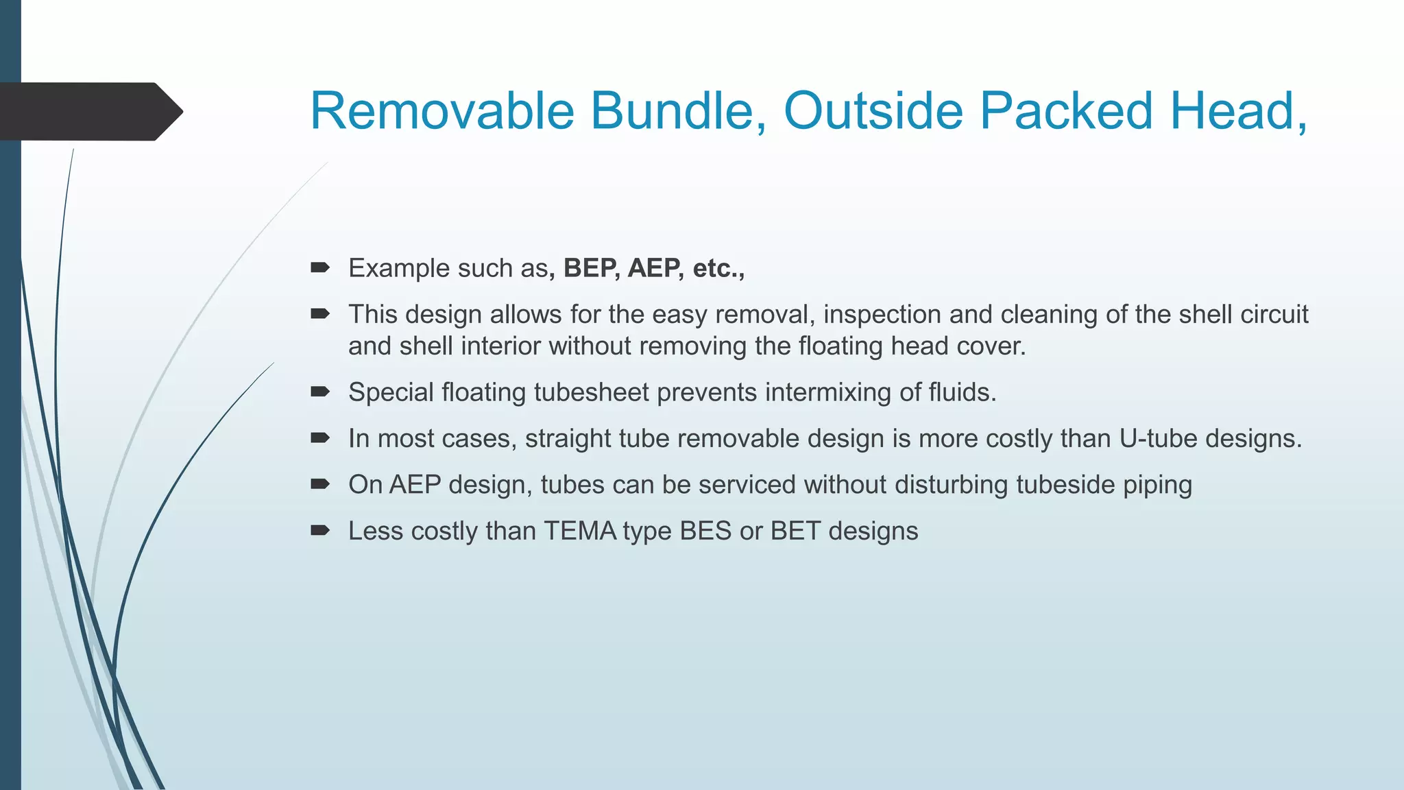
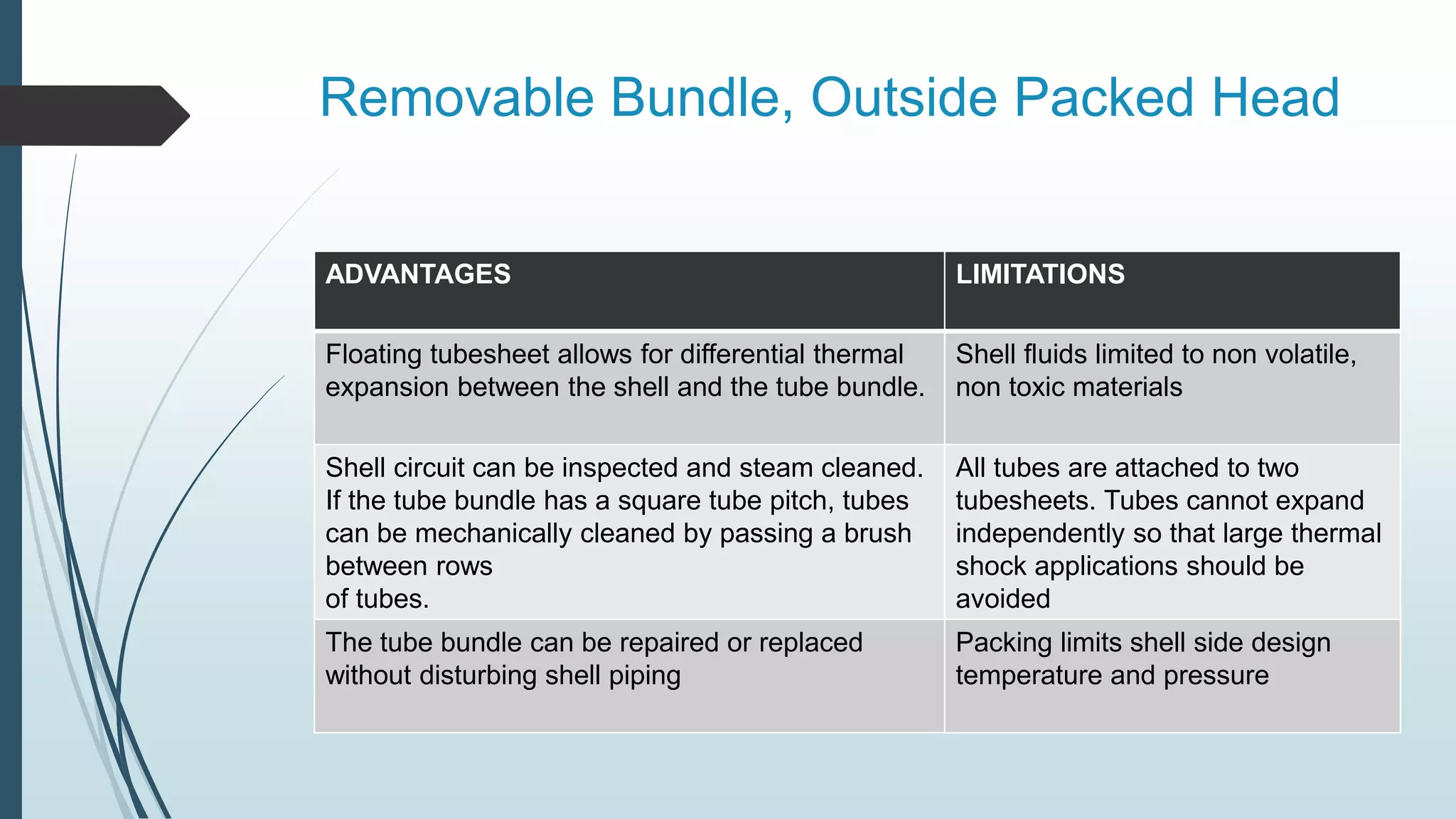
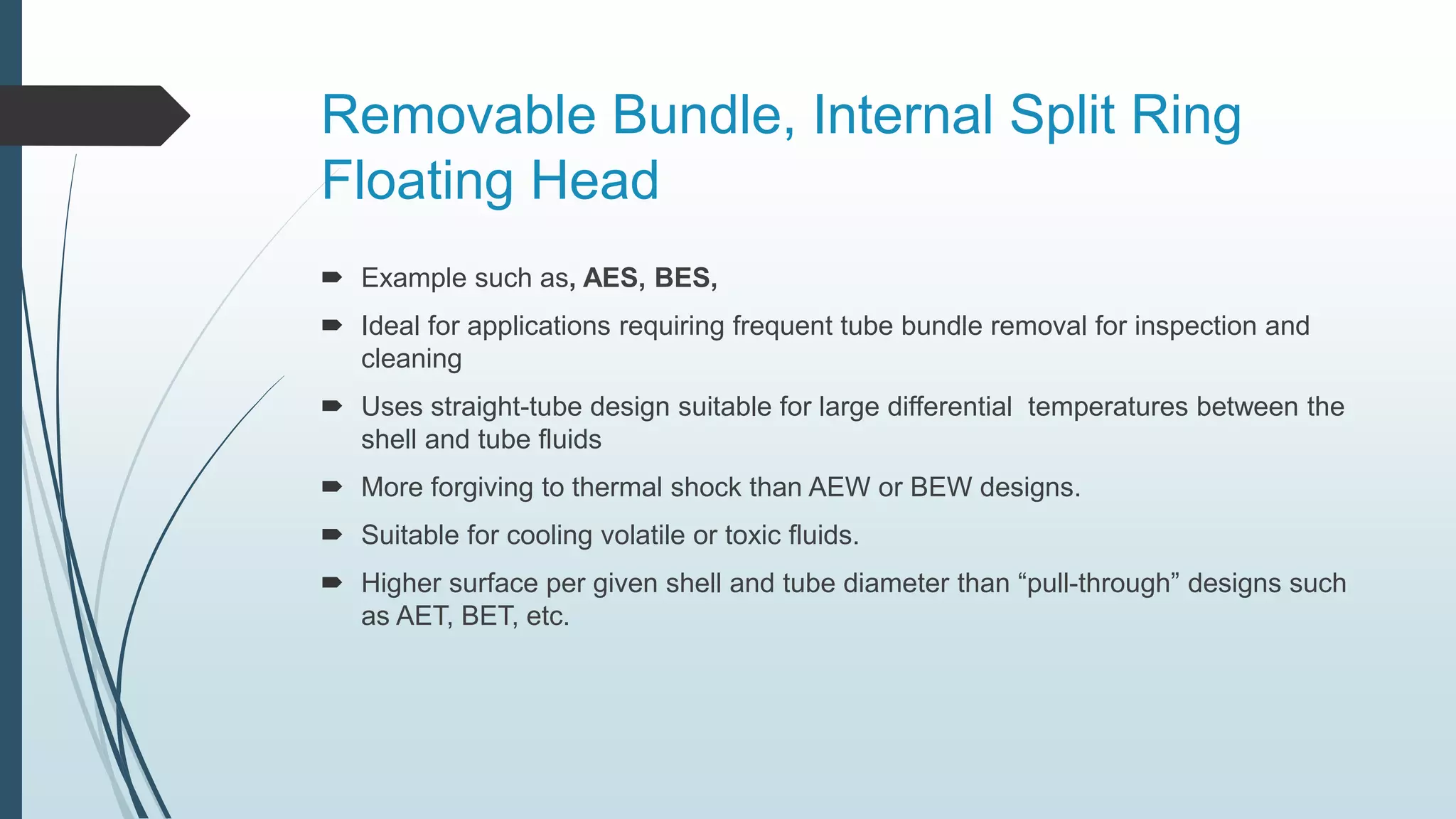
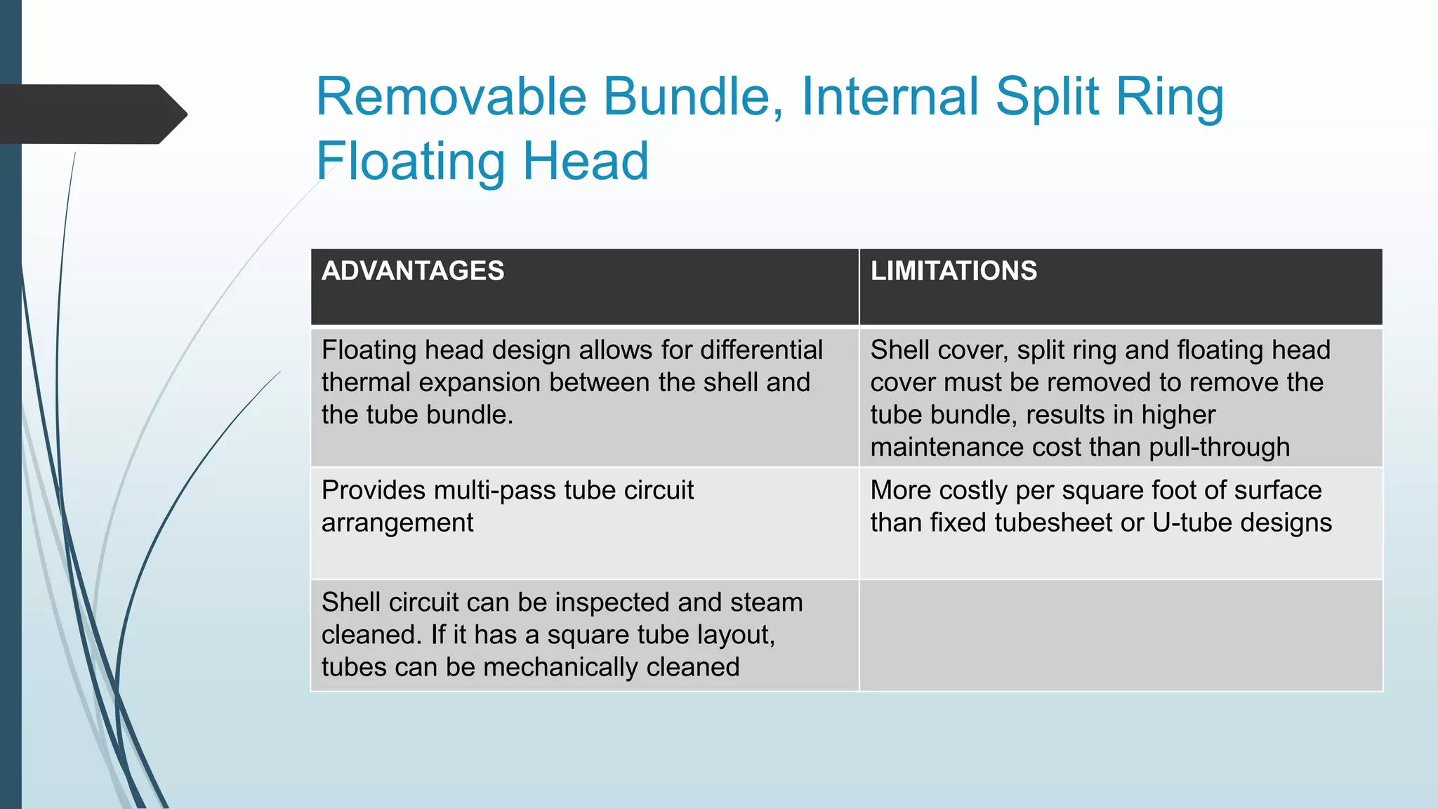
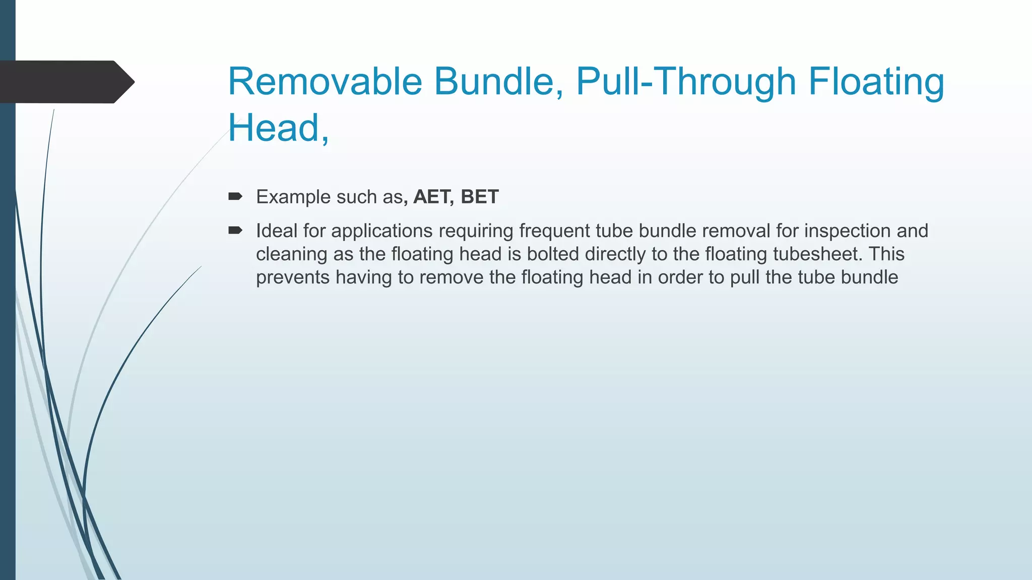
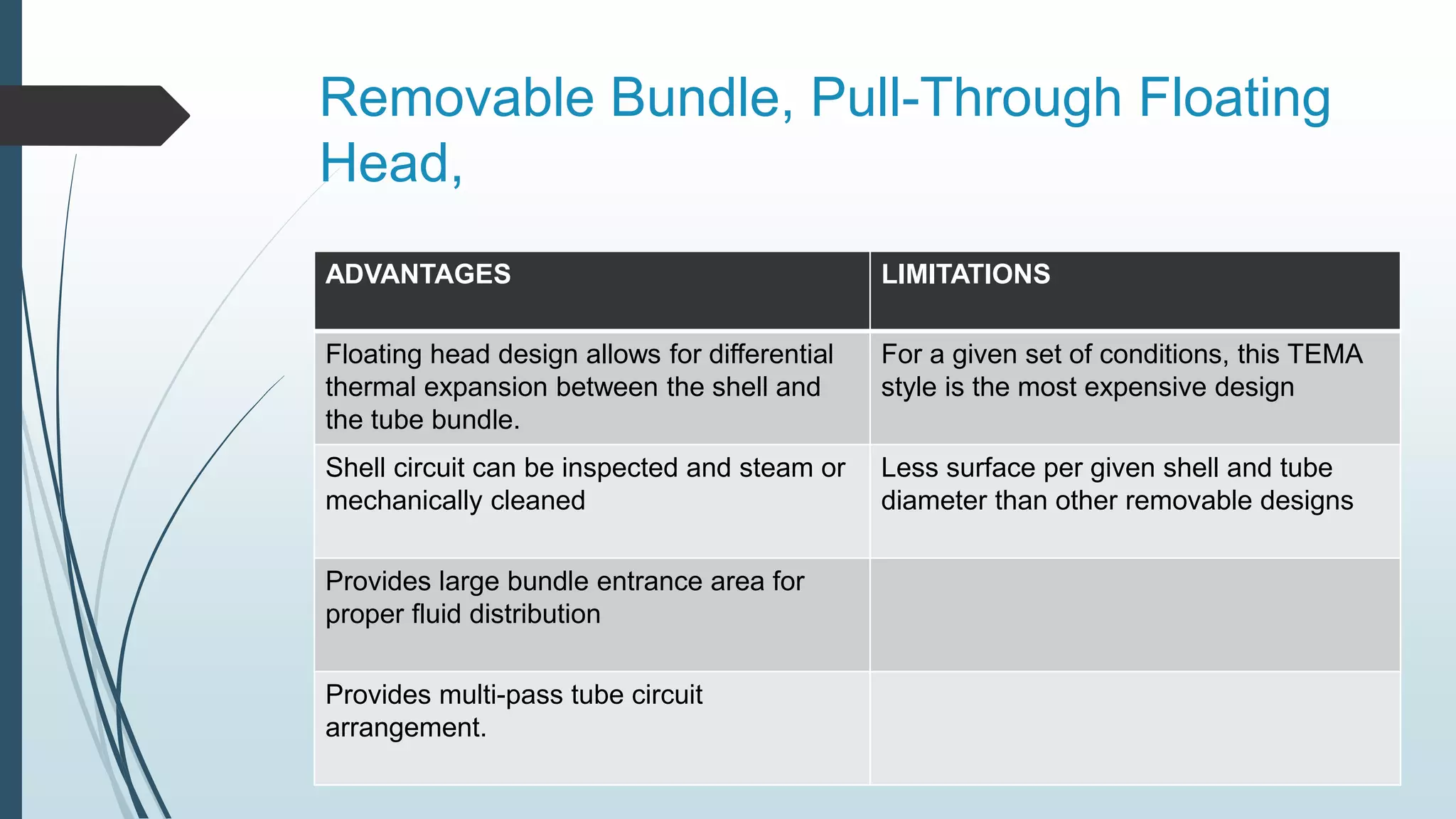
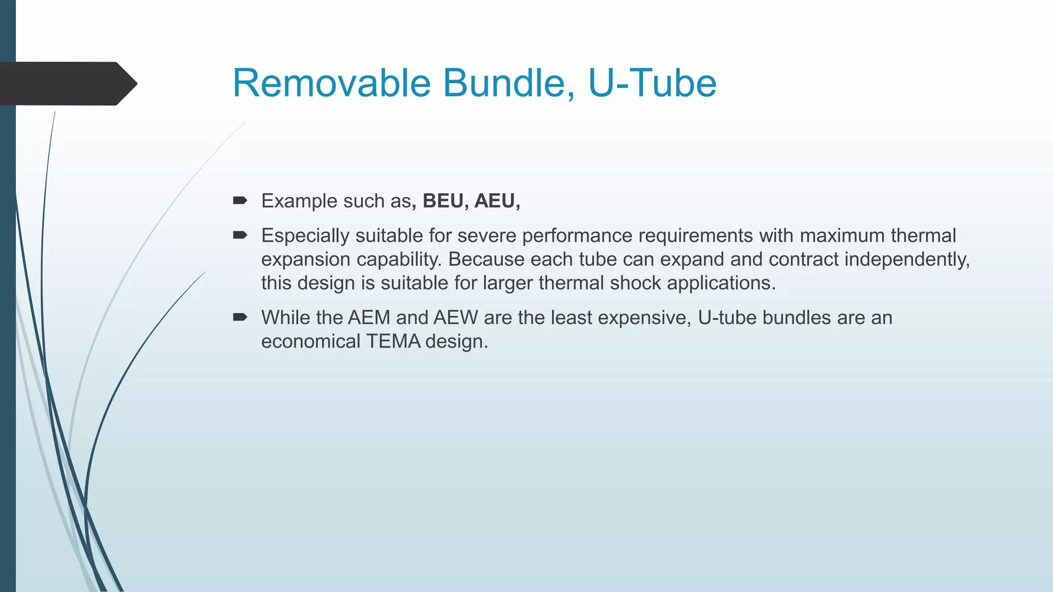
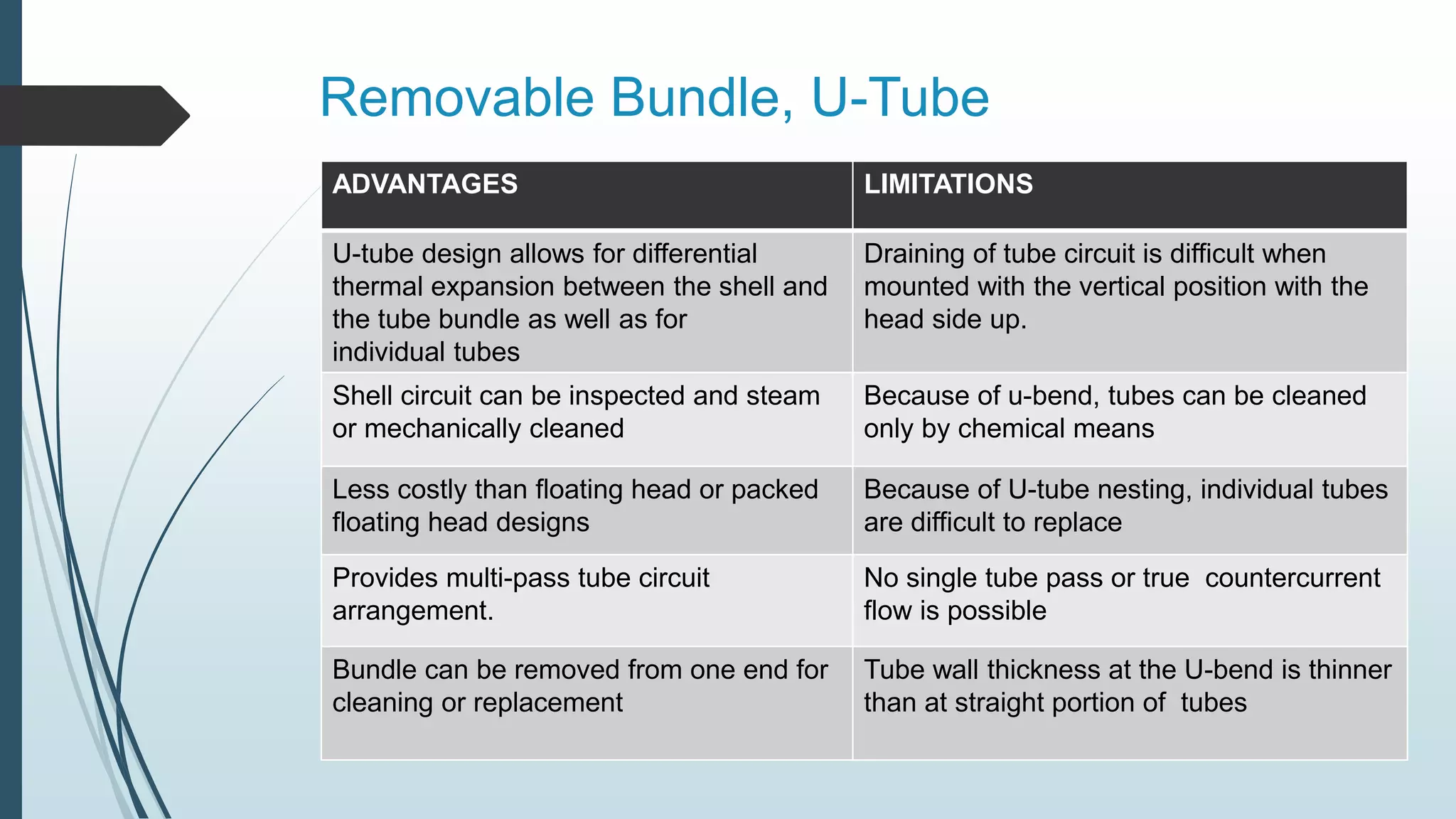
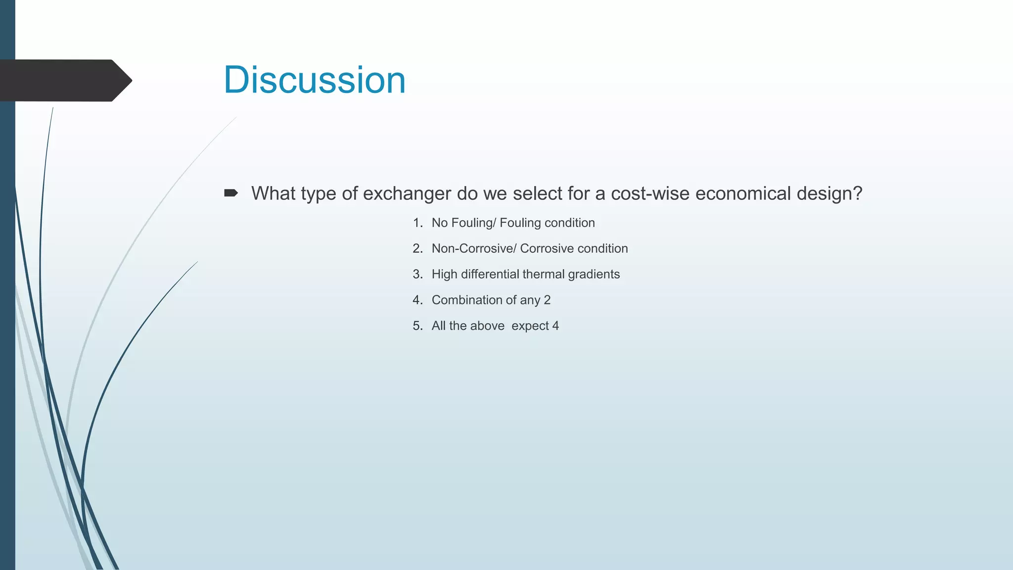


The document provides a comprehensive overview of the selection process for shell and tube heat exchangers (STHE), detailing various design types, components, and their advantages and limitations. It discusses factors such as cost, maintenance, and fluid characteristics, while also highlighting specific applications for different exchanger designs. Additionally, it covers baffle design, tube layout, and provides quizzes for front end and rear end selection regarding heat exchangers.


