actel fpga problems
•
3 likes•1,720 views

This document provides solutions to several digital logic design problems involving implementations using logic modules (LMs). It includes implementations of a 3-bit up counter, 3-bit Johnson counter, SR latch, 3-bit binary to gray code converter, and 3-bit gray to binary code converter. Design equations are derived using Shannon expansion and Karnaugh maps. The number of required ACT1 or ACT2 LMs for each implementation is specified. Transparent low and high latches are also defined.

Recommended
More Related Content
What's hot
What's hot (20)
Viewers also liked
Viewers also liked (19)
Similar to actel fpga problems
Similar to actel fpga problems (20)
Recently uploaded
Recently uploaded (20)
actel fpga problems
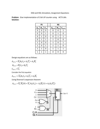
- 1. DSD and HDL Simulation, Assignment Questions Problem Give implementation of 3 bit UP counter using ACT3 LMs Solution: PS NS 𝑨 𝑩 𝑪 𝑨 𝑩 𝑪 0 0 0 0 0 1 0 0 1 0 1 0 0 1 0 0 1 1 0 1 1 1 0 0 1 0 0 1 0 1 1 0 1 1 1 0 1 1 0 1 1 1 1 1 1 0 0 0 Design equations are as follows: 𝐴 = 𝐴̅̅̅̅ 𝐵 𝐶 + 𝐴 𝐶̅̅̅ + 𝐴 𝐵̅̅̅ 𝐵 = 𝐵̅̅̅ 𝐶 + 𝐵 𝐶̅̅̅ 𝐶 = 𝐶̅̅̅ Consider the first equation 𝐴 = 𝐴̅̅̅̅ 𝐵 𝐶 + 𝐴 𝐶̅̅̅ + 𝐴 𝐵̅̅̅ Using Shannon’s expansion theorem 𝐴 = 𝐴̅̅̅̅ 𝐵̅̅̅(0) + 𝐴̅̅̅̅ 𝐵 (𝐶 ) + 𝐴 𝐵̅̅̅(1) + 𝐴 𝐵 (𝐶̅̅̅)
- 2. Consider the second equation 𝐵 = 𝐵̅̅̅ 𝐶 + 𝐵 𝐶̅̅̅ Using Shannon’s expansion theorem 𝐵 = 𝐵̅̅̅ 𝐶̅̅̅(0) + 𝐵̅̅̅ 𝐶 (1) + 𝐵 𝐶̅̅̅(1) + 𝐵 𝐶 (0) Similarly, implement the third equation ------------------------------------------------------------------------------------------------------------------------------- Problem Give implementations of 3 bit Johnson (or twisted ring) counter using ACT2 LM Solution: PS NS 𝑨 𝑩 𝑪 𝑨 𝑩 𝑪 0 0 0 1 0 0 1 0 0 1 1 0 1 1 0 1 1 1 1 1 1 0 1 1 0 1 1 0 0 1 0 0 1 0 0 0 Design equations are 𝑨 = 𝐶̅̅̅ ; 𝑩 = 𝐴 ; 𝑪 = 𝐵 3 ACT2- S LMs are required
- 3. Similarly, implement Bn+1, Cn+1 Problem Give implementation of SR latch using ACT1 series Solution: Consider the TT S R Operation X 1 0 Set 1 X 0 1 Reset 0 0 0 0 Last state 0 1 0 0 1 X 1 1 Forbidden X X-Don’t care Reduced implicant table is shown to be S R X 1 X 1 1 X 0 1 = + ̅ Using Shannon’s expansion theorem = ( ) + ̅( ̅ ) ̅ = ( ) + ̅( )
- 4. Problem Give implementation of 3 bit binary- to-gray code converter using ACT1 series Solution: Binary input Gray code output 𝑩 MSB 𝑩 𝑩 𝑮 MSB 𝑮 𝑮 0 0 0 0 0 0 0 0 1 0 0 1 0 1 0 0 1 1 0 1 1 0 1 0 1 0 0 1 1 0 1 0 1 1 1 1 1 1 0 1 0 1 1 1 1 1 0 0 Note that gray code satisfies unit distance property, reflective and cyclic property. Considering K-map, it can be shown that = 𝐵 = 𝐵 𝐵 = 𝐵 𝐵 2 ACT1 LMs are sufficient to implement 3 bit binary- to- gray code converter Problem Give implementation of 3 bit gray- to-binary code converter using ACT1 series Solution:
- 5. Gray code input Binary output 𝑮 MSB 𝑮 𝑮 𝑩 MSB 𝑩 𝑩 0 0 0 0 0 0 0 0 1 0 0 1 0 1 1 0 1 0 0 1 0 0 1 1 1 1 0 1 0 0 1 1 1 1 0 1 1 0 1 1 1 0 1 0 0 1 1 1 Considering K-map, it can be shown that 𝐵 = 𝐵 = 𝐵 = These equations can be further simplified as given below (so as to reduce the number of LMs required): 𝐵 = 𝐵 = 𝐵 𝐵 = 𝐵 2 ACT1 LMs are sufficient to implement 3 bit gray- to-binary code converter Transparent low latch If C = 0, Q = D then it is known as transparent low latch as shown. Transparent high latch If C = 1, Q = D then it is known as transparent high latch. Dr. D. V. Kamath Professor, Dept. of E&C Engg., MIT