Downloaded 549 times

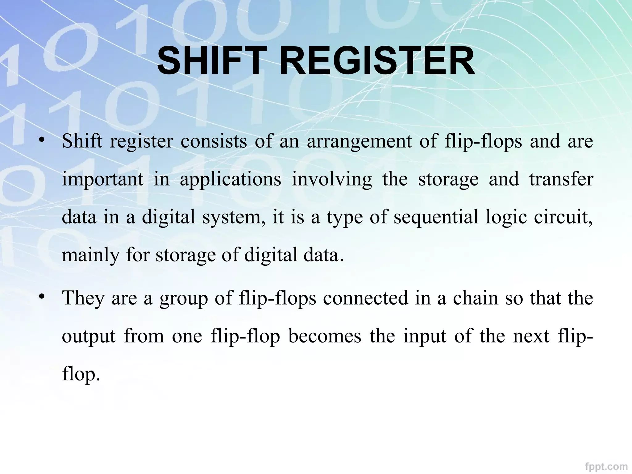
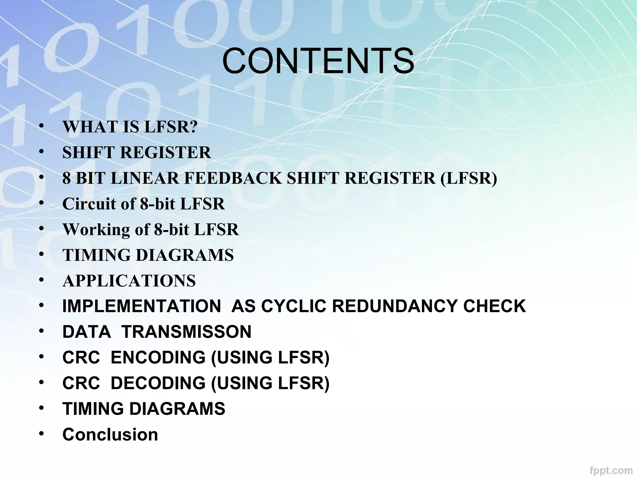
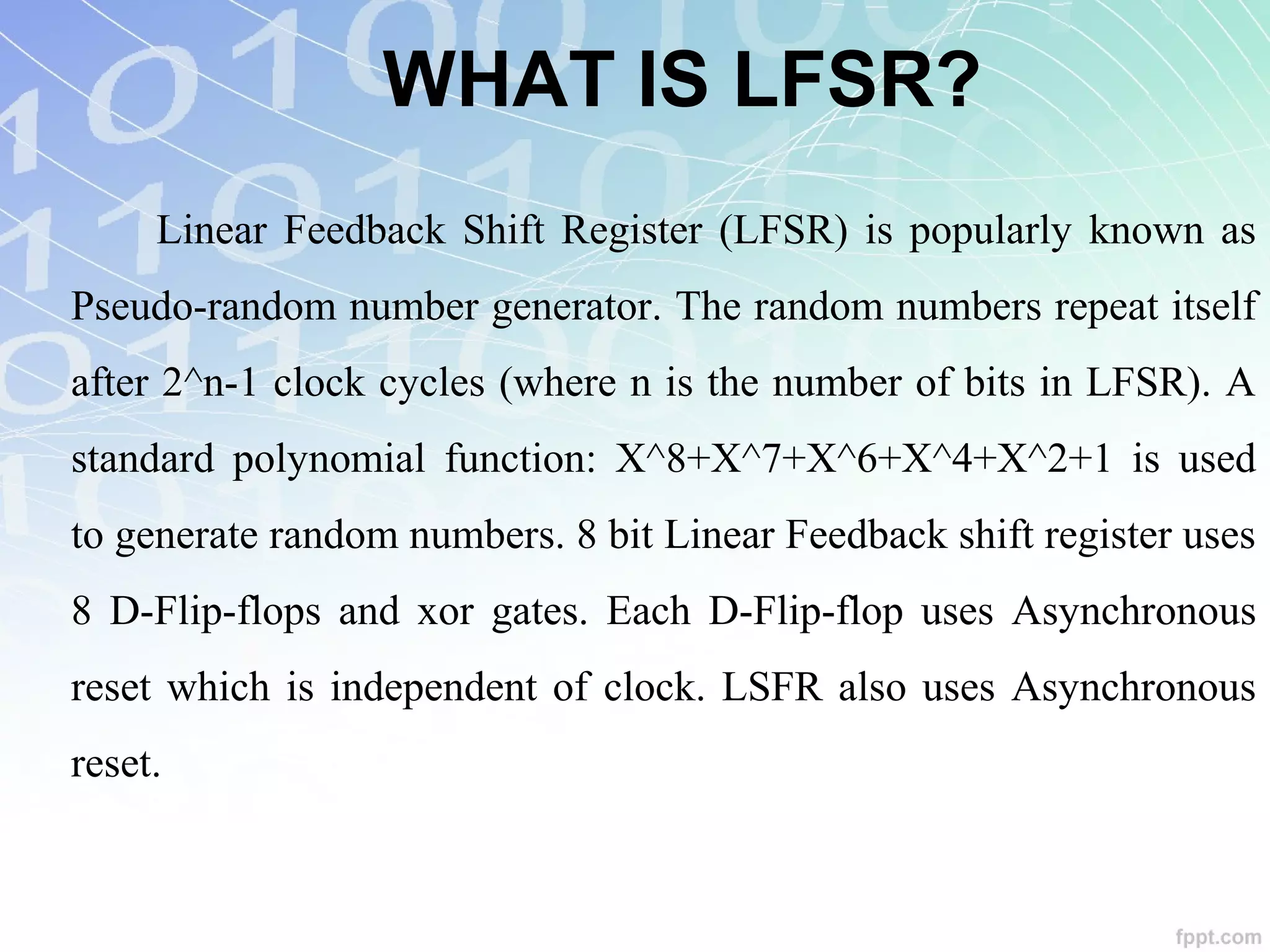
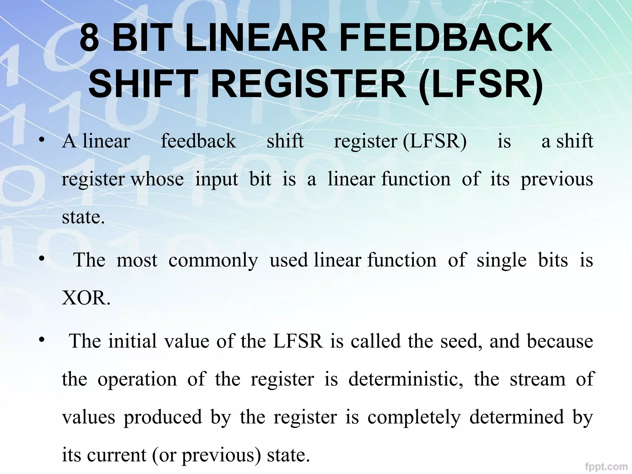
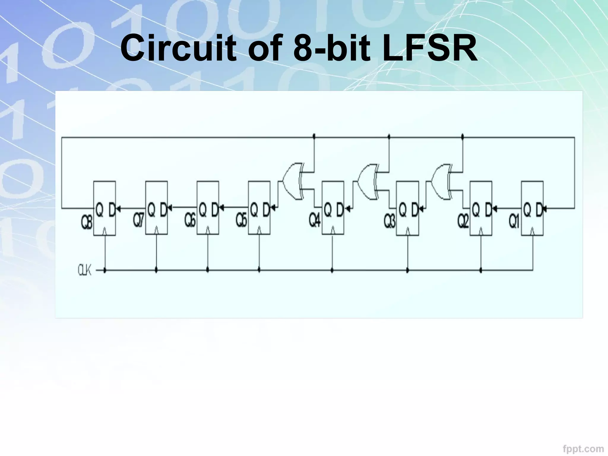
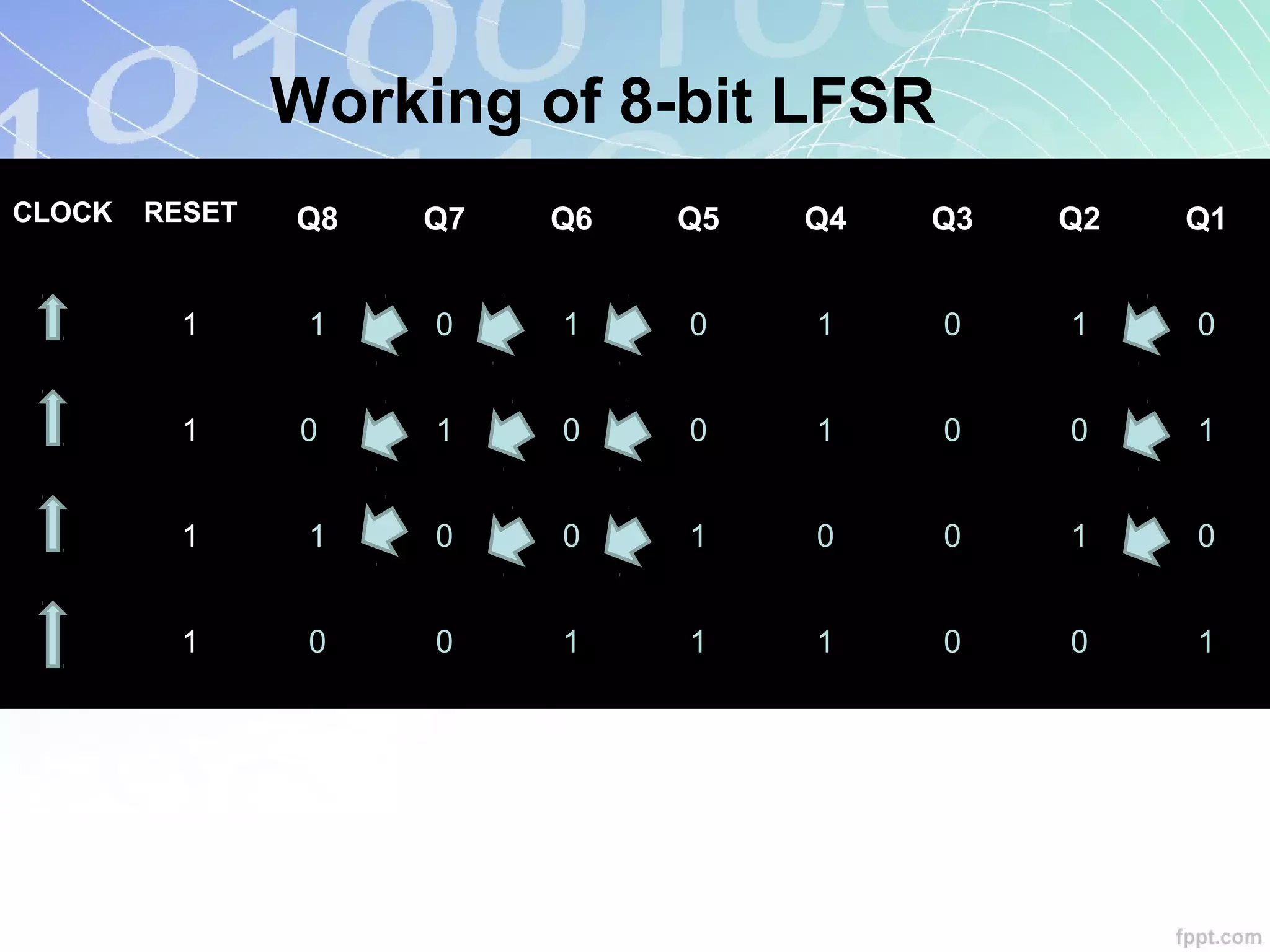
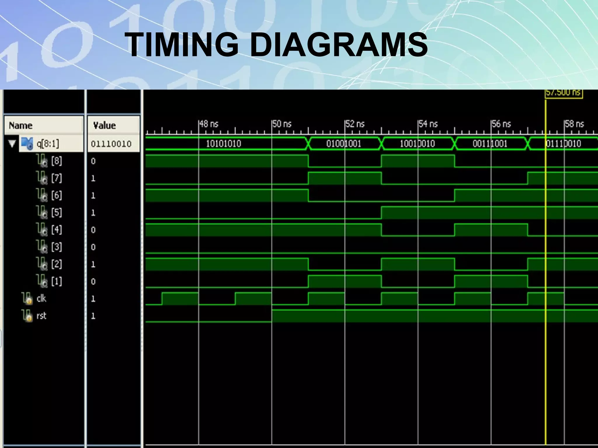
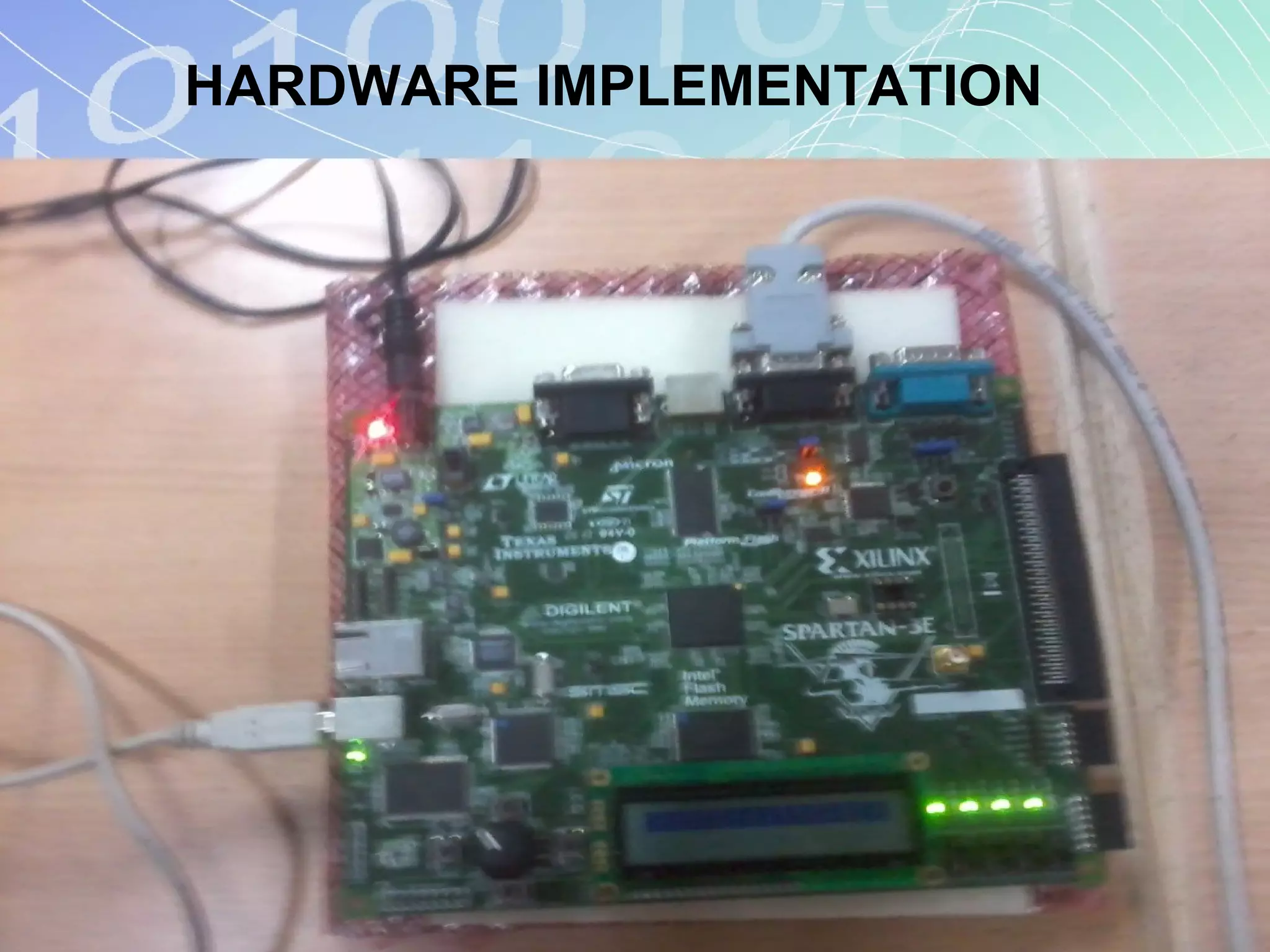
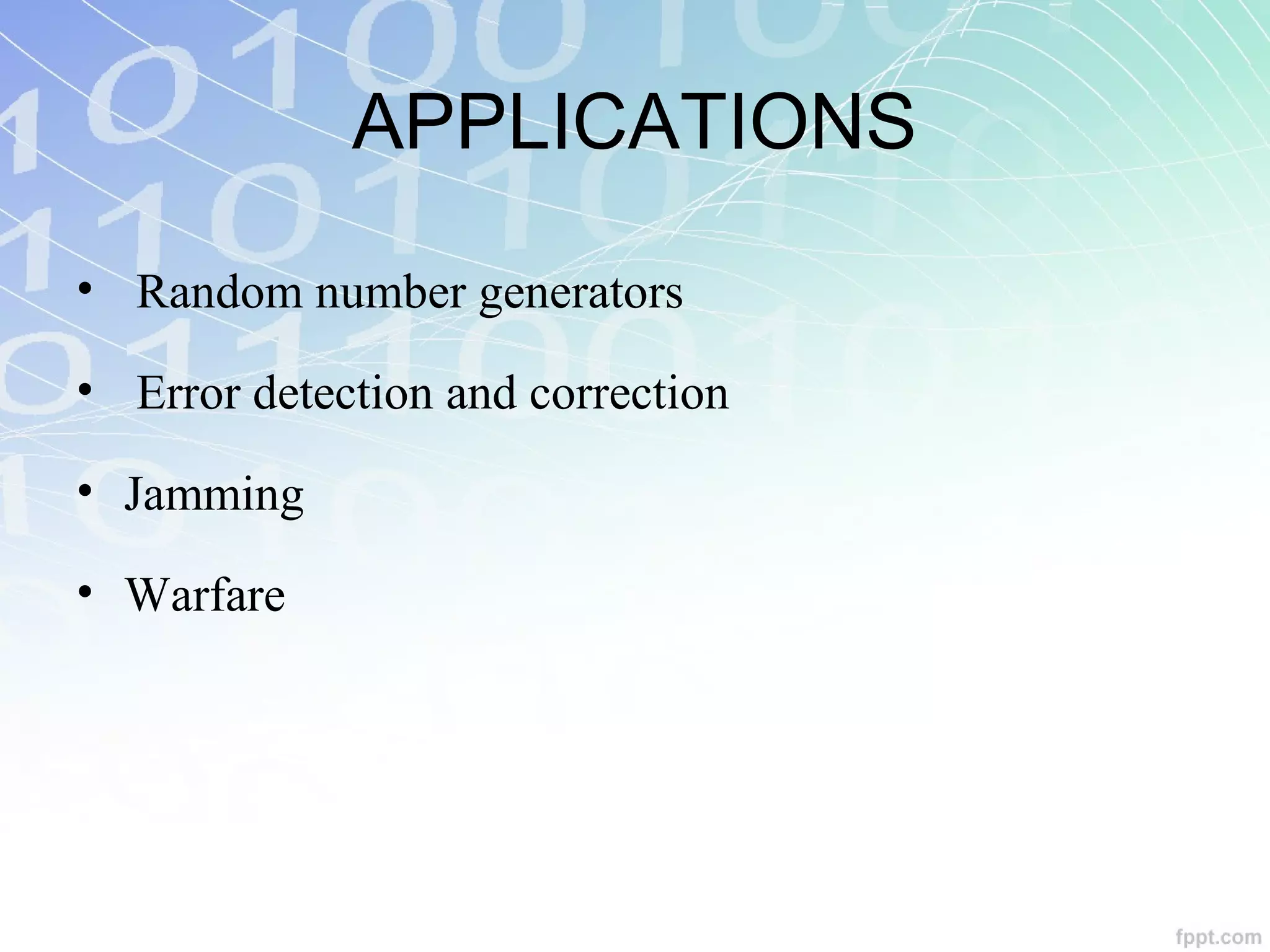
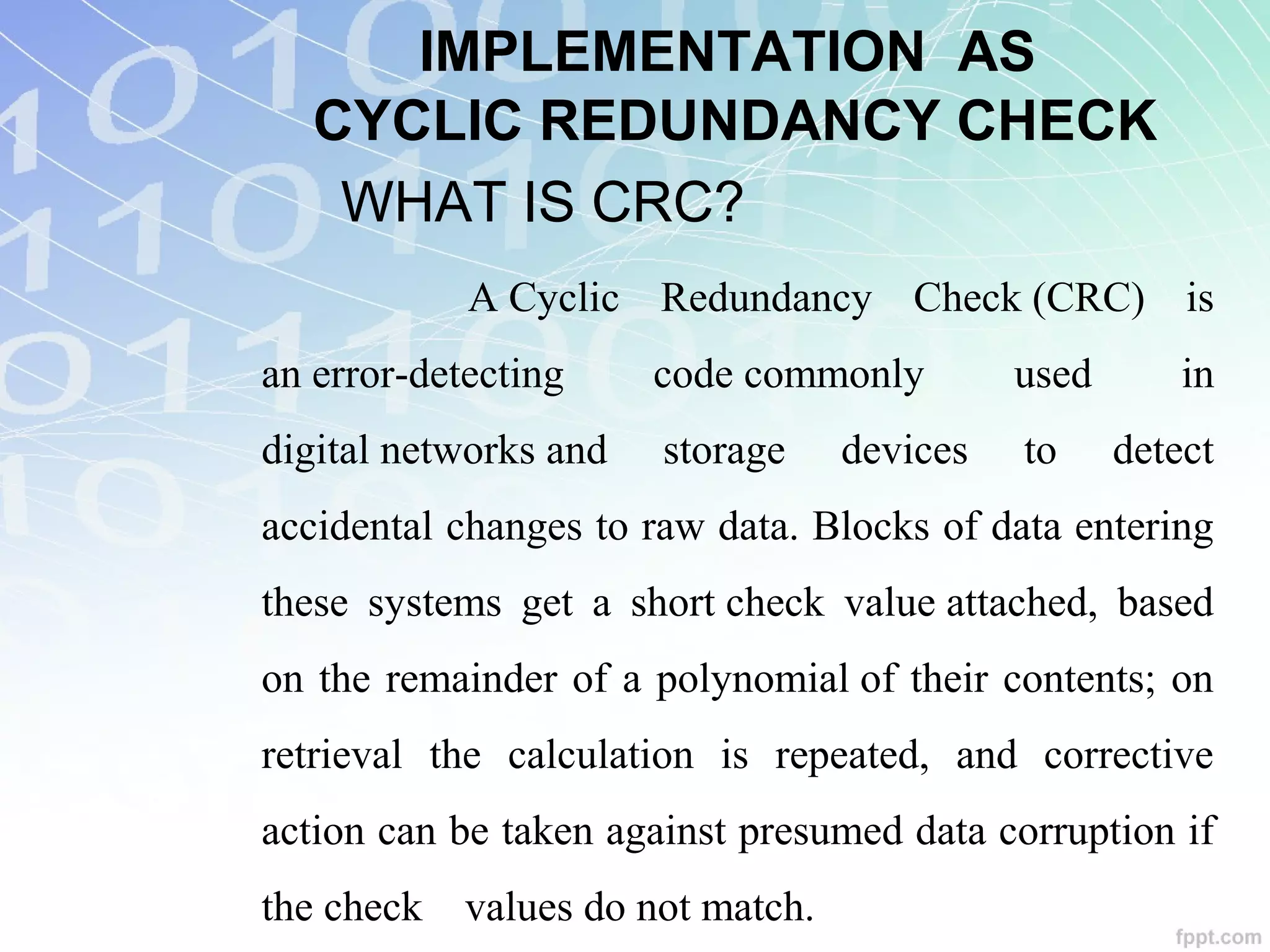
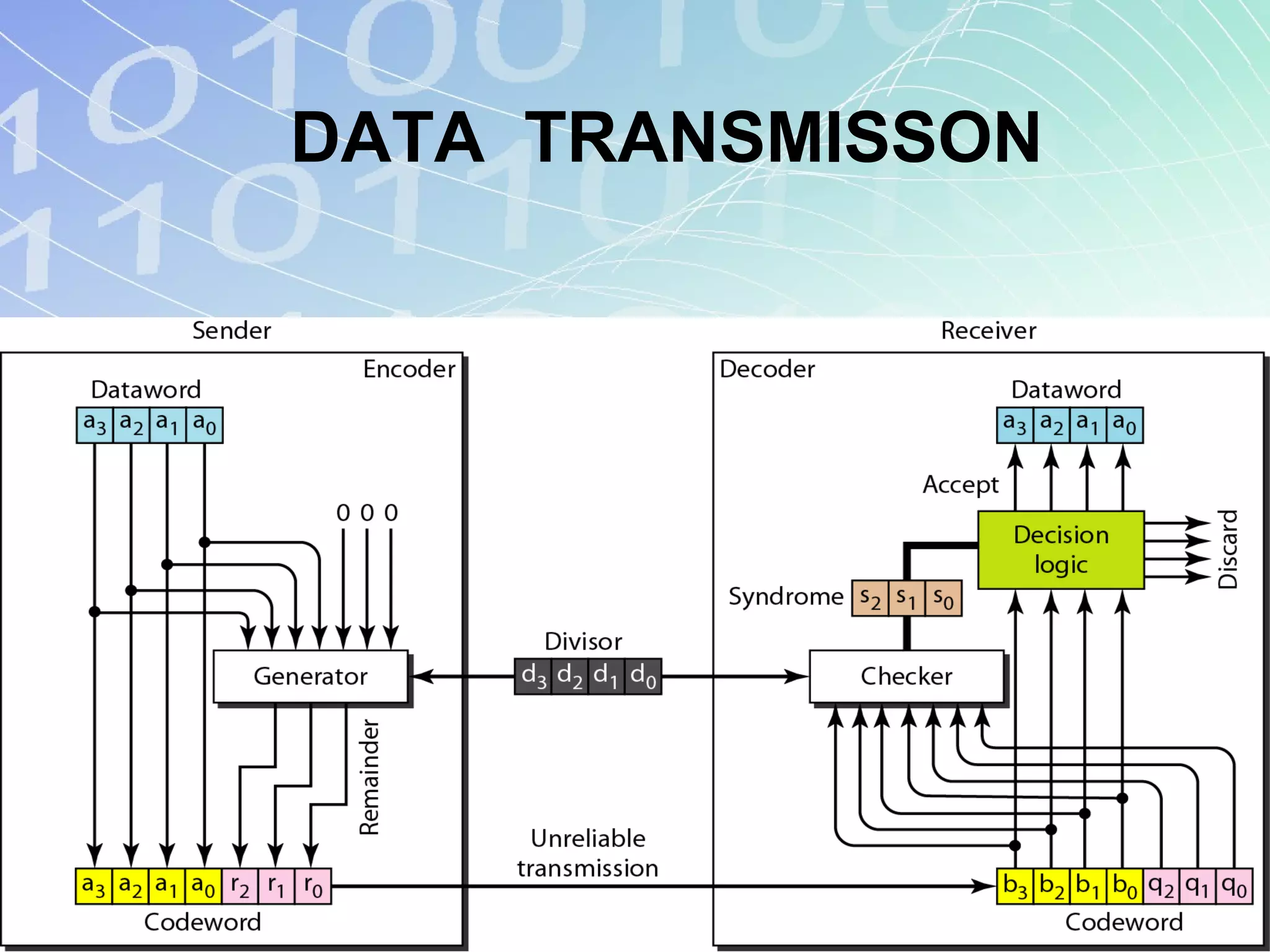
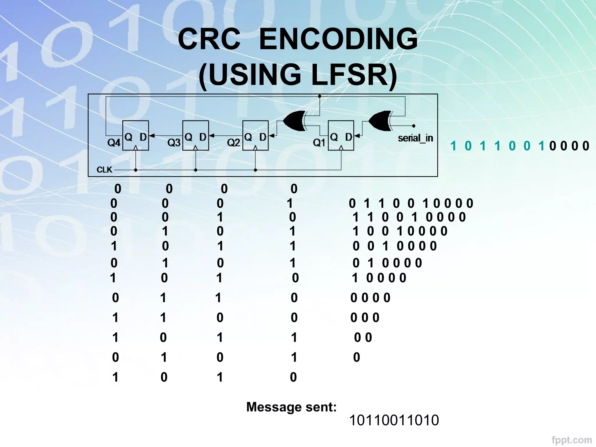
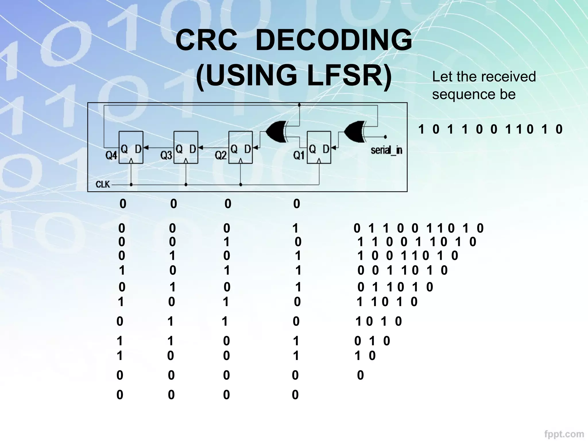
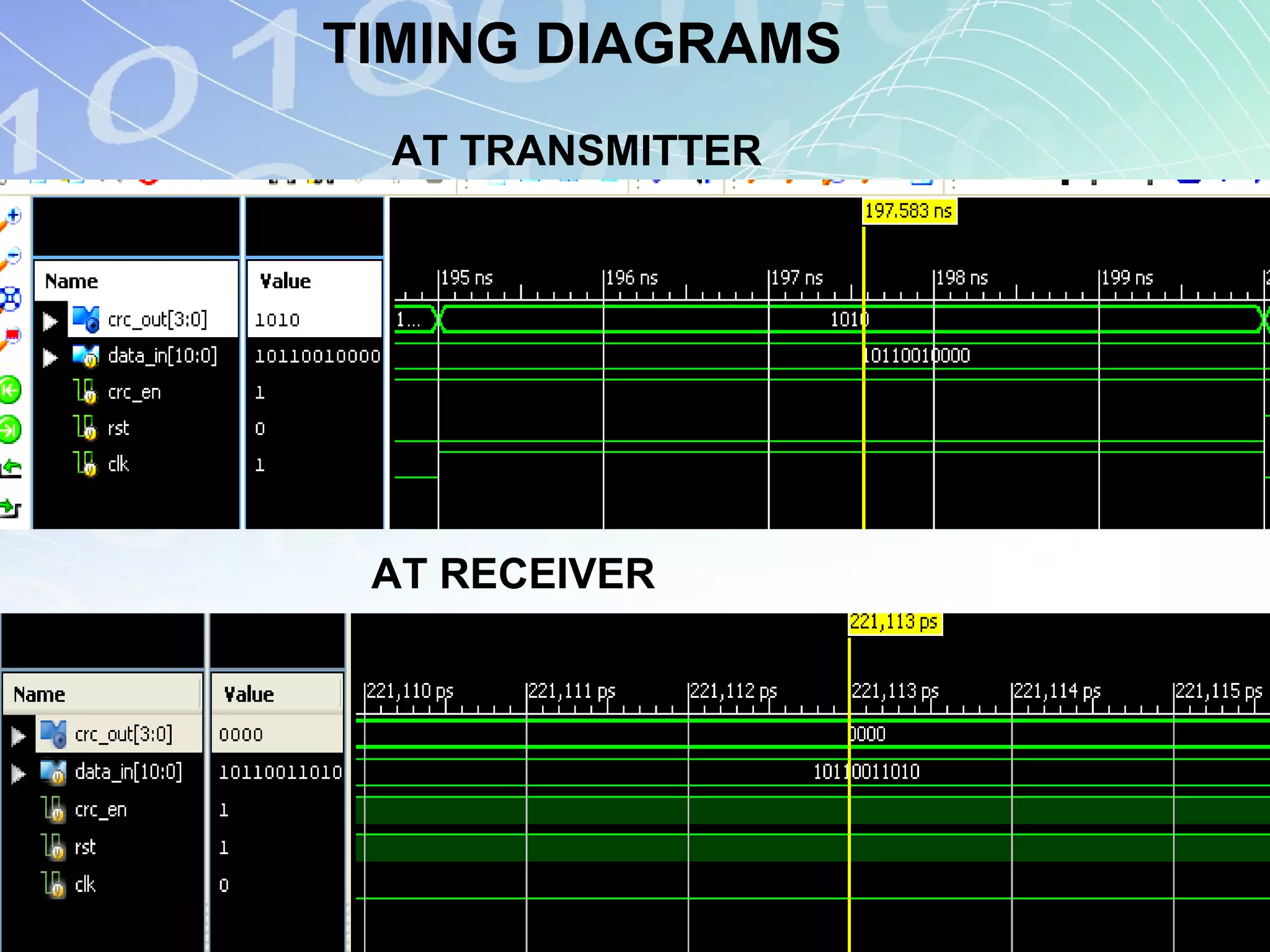


This document presents a mini project on linear feedback shift registers (LFSRs). It describes how an 8-bit LFSR works using 8 D-flip flops connected in a chain with outputs XORed together. The LFSR generates a pseudo-random sequence that repeats after 255 cycles. It discusses the circuit, working, and timing diagrams of the 8-bit LFSR. Applications mentioned include random number generation, error detection/correction, and implementing cyclic redundancy checks for data transmission.


![208224019-20_testing_ppt[1][1][1]_1[1][1].pptx](https://cdn.slidesharecdn.com/ss_thumbnails/208224019-20testingppt111111-250415093818-44899f27-thumbnail.jpg?width=640&height=640&fit=bounds)


![[IJET V2I3P1] Authors: G Hemanth kumar Dr. M. Saravanan, Charan kumar. K](https://cdn.slidesharecdn.com/ss_thumbnails/ijet-v2i3p1-160609050730-thumbnail.jpg?width=640&height=640&fit=bounds)