
Recommended
More Related Content
What's hot
What's hot (20)
Similar to TDA2822 audio amplifier IC features, pin functions and application circuits
Similar to TDA2822 audio amplifier IC features, pin functions and application circuits (20)
More from Vinsion Chan
More from Vinsion Chan (14)
Recently uploaded
Recently uploaded (20)
TDA2822 audio amplifier IC features, pin functions and application circuits
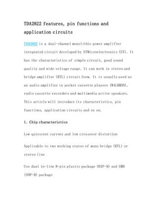
- 1. TDA2822 features, pin functions and application circuits TDA2822 is a dual-channel monolithic power amplifier integrated circuit developed by STMicroelectronics (ST). It has the characteristics of simple circuit, good sound quality and wide voltage range. It can work in stereo and bridge amplifier (BTL) circuit form. It is usually used as an audio amplifier in pocket cassette players (WALKMAN), radio cassette recorders and multimedia active speakers. This article will introduce its characteristics, pin functions, application circuits and so on. 1. Chip characteristics Low quiescent current and low crossover distortion Applicable to two working states of mono bridge (BTL) or stereo line Use dual in-line 8-pin plastic package (DIP-8) and SMD (SOP-8) package
- 2. Wide power supply voltage range (1.8 ~ 15V, TDA2822M), it can still work when the power supply voltage is as low as 1.8V 2. Structure diagram Figure 2 TDA2822 structure diagram 3. Pin configuration
- 3. Figure 3 TDA2822 pin arrangement diagram Pin function table Pin number symbol functions 1 OUT(1) 1 Channel output 2 Vcc power supply 3 OUT(2) 2 Channel output 4 GND Ground 5 IN-(2) 2 Channel inverting input 6 IN+(2) 2 Channel non- inverting input
- 4. 7 IN+(1) 1 Channel non- inverting input 8 IN-(1) 1 Channel inverting input 4. Working voltage The working voltage of tda2822 is divided into two types: one 3-6V; the other 9-12V. In fact, his minimum working voltage can reach 1.8V. Storage temperature 5. Application circuit Stereo application circuit
- 5. Figure 4 Typical application of Stereo stereo amplifier Mono BTL application circuit Figure 5 Typical application of Bridge Mono Bridge (BTL) amplifier 6. Example application
- 6. Figure 6 is the microphone amplifier circuit of this microphone, with few external components, simple production, but unexpectedly good sound quality. Using a dual-channel audio amplifier integrated circuit. Its main features are high efficiency and low power consumption. The typical value of the quiescent operating current is only about 6mA. The integrated circuit has strong voltage adaptability (1.8V ~ 15VDC). Even when used at a low voltage of 1.8V, there will still be about 100mW Power output, as shown in the figure. Figure 6 microphone power amplifier circuit diagram Working principle
- 7. The electret microphone MIC converts the picked-up sound signal into an electrical signal, then introduces it from the ② pin of U1 through C2 and W, and after the audio amplification of U1, the speaker is pushed to pronounce. This machine is connected to a BTL output circuit, which is good for improving sound quality and reducing distortion. At the same time, the output power is also increased by 4 times. When 3V power is supplied, the output power is 350mW.