
Recommended
More Related Content
What's hot
What's hot (20)
Similar to Comparative Study of Audio Amplifiers
Similar to Comparative Study of Audio Amplifiers (20)
More from IOSRJECE
More from IOSRJECE (20)
Recently uploaded
Recently uploaded (20)
Comparative Study of Audio Amplifiers
- 1. IOSR Journal of Electronics and Communication Engineering (IOSR-JECE) e-ISSN: 2278-2834,p- ISSN: 2278-8735.Volume 12, Issue 1, Ver. I (Jan.-Feb. 2017), PP 32-36 www.iosrjournals.org DOI: 10.9790/2834-1201013236 www.iosrjournals.org 32 | Page Comparative Study of Audio Amplifiers Vimal Raj V1 , Aravindan S2 , Agnishwar Jayaprakash3 , Harith M4 , Manivannan R5 , Bhuvaneshwaran G6 1 (CEO, Garuda Aerospace Pvt. Ltd., India) 2 (Electronics Engineer, Garuda Aerospace Pvt. Ltd., India) 3 (Managing Director, Garuda Aerospace Pvt. Ltd., India) 4 (Head Innovation, Garuda Aerospace Pvt. Ltd., India) 5 (Electronics Engineer, Garuda Aerospace Pvt. Ltd., India) 6 (Electronics Engineer, Garuda Aerospace Pvt. Ltd., India) Abstract: The Audio power amplifier design needs knowledge of both art and electronics. It is an electronic device which is used to increase the Amplitude of the signa1 i.e.: To increase the loudness of the signal, which is measured in decibels (dB).In Audio amplifier power of the signal is increased, so its energy in the Audio signal from the output of the amplifier can be converted into sound using speakers. This research focuses the analysis of different Audio amplifiers, In this paper circuits with LM386,LM358N, LM3886, TIP series Amplifier and TIP series cascaded with LM358N amplifier circuits are used, These IC’s were selected in accordance with their power gain factor. This analysis figure out the efficiency of each circuits in terms of Power supplies, and also the size of the circuit, which will help to choose the best available audio amplifiers as per the requirements. Keywords: Audio Amplifier, Class AB Amplifier, Decibels, Modulation, Operational Amplifier, Power Amplifier. I. Introduction Sound is an energy or wave made by vibration. When object vibrates, it causes flow in the air particles. These particles collided with each other, which makes them vibrate. This flow is called sound waves, these waves keeps on going until they run out of energy. In some cases sound energy will be low and not audible. To increases the sound energy, Amplifiers are preferred.Amplifiers are basically used to superimpose the audio signal which should have the capability to drive a loudspeaker whether it is live audio or Recorded Audio. The Signal frequency should be the range between 20- 20000Hz, is comfortable for human hearing. Design parameters for audio amplifiers include gain, frequency response, distortion and noise. The input signal of an audio amplifier may only measure a few hundred microwatts, but its output can be tens or even thousands of watts. Audio amplifier was 1st invented in 1909 by Lee De Forest (triode vacuum tube). Power Amplifiers were developing in the late 1960s. This is not just limited to the high end where audio Mystique has a strong influence. On olden days only transformers were used to amplify the audio signal, which were bulk and many limitation. As the result of electronic evolution these amplification is done using IC’s, Which result in smaller size and less bulkier, and In nowadays the transformers are used only to provide maximum power transfer for impedance matching between input and output, While there is a tremendous amount of science to the Design of audio power amplifiers, there are also many nuances that demand attention to detail. It is important that power Audio amplifiers produce low noise, since the noise they make is always there, independent of the volume control setting and the listening level. This is particularly so when the amplifiers are used with high-efficiency loudspeakers. The noise is usually specified as being so many decibels down from either the maximum output power.This paper is organized with the following sections: Section II describes existing audio amplifiers. Section III gives the comparison and observation. Finally, the paper is concluded in Section IV. II. Existing Audio Amplifiers A.Circuit Using Lm386 LM386 is a low power audio frequency amplifier. It consume low power (mostly batteries). The type of IC is an 8-pin mini-DIP package. It can also be used as a pre Amplifier. This IC is initially deliver a voltage gain of 20 dB.Without adding external parts. But this voltage gain can be raised up to 200dB by external components. In figure1, the gain of LM386, internally the set to 20 but it can be increased up to 200 by using a capacitor between PIN 1 and 8. We have used 10uF capacitor C1 to get the highest gain i.e. 200. Gain can be adjusted to any value between 20 to 200 by changing capacitor value. PIN 2 and PIN 3 are the input PINs for sound signals. Pin 2 is the negative input terminal, connected to the ground. Pin 3 is the positive input terminal, in which sound signal is fed to be amplified. In our circuit it is connected to the positive terminal of the condenser mic with a 100k potentiometer RV1. Potentiometer acts as volume control knob. .A capacitor C5 of
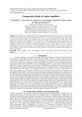
- 2. ComparativeStudy of Audio Amplifiers DOI: 10.9790/2834-1201013236 www.iosrjournals.org 33 | Page 0.1uF has also been used along with potentiometer, to remove the DC component of input signal and only allow audio (AC component) to be fed into LM386. Figure 1 Circuit using LM386 B. Circuit Using Lm3886 The LM3886 is a high-performance 150W audio power Amplifier with Mute function. It can maintains an excellent signal-to-noise ratio of greater than 92dB with a typical low noise floor of 2.0μV. A maximum output power obtain by this ICs is 63 watts into 8 ohms.Reduced the load impedance to 4 ohms that improve the output power to greater than 108 watts. In practice, the watts will be depended on the quality of the music. The performance of the audio power LM3886, say NS, utilizing its Self-Peak Instantaneous Temperature (K) (Spike) protection circuitry, puts in a class above discrete and hybrid amplifiers by providing an inherently, dynamically protected Safe Operating Area (SOA).The special feature of this amplifier is a mute option. In figure 2, We have to give a proper capacitor to ground to disable the mute option. PIN 9& 10 are the non- inverting and inverting Input of the LM3886 that is an audio input of the ICs, we filter input audio signal using 10uF capacitor followed by non-inverting terminal. PIN 3 is connected in 4700uF/50V capacitor for output Filter, When the transistor reaches the biasing voltage, it supplies the +Vcc to the inverting terminal. Figure 2 Circuit using LM3886 C. Circuit Using Lm358n The preamplifier LM358N is added with the Audio amplifier, to increase the voltage gain as well as the loudness of the amplifier. Thus input of main amplifier is fed from the output of preamplifier, instead of getting directly from the source. So the audio signal is amplified with small amount of gain by preamplifier LM358N and further amplified by the main amplifier. In figure 3 it can be given power supply up to 12v, In case of using Power adopter use capacitor of 0.1uF to eliminate DC noise. The result of cascading LM358N and TIP Amplifier is tabulated below.
- 3. ComparativeStudy of Audio Amplifiers DOI: 10.9790/2834-1201013236 www.iosrjournals.org 34 | Page Figure 3 Circuit using LM358N D. Tip Series: This circuit Contain TIP 142, TIP 147, TIP 41C. TIP 147 and 142 are complementary Darlington pair transistors which can handle 5 A current and 100V.TIP41C is NPN Epitaxial Silicon Transistor which can handle 6A current and 100V Figure 4 TIP Series TIP 142 ,TIP 147 together with TIP41 (Q1,Q2,Q3) is used for driving the speaker and Two BC 558 transistors Q4 and Q5 are wired as pre amplifier and This circuit is designed so rugged that this can be assembled even on a perfect board or even by pin to pin soldering. The circuit can be powered from a +/- 45 V dual power supply. Since this amplifier requires negative as well as positive voltage, transformers can used. In case of using battery, connect batteries in series .for example connect 3s, 4s,3s,4s LiPo batteries in series consider both ends as positive and negative voltages, and center of the series connection as virtual ground. By using the end positive terminal and virtual ground we can get the positive voltage and the negative terminal and virtual ground we can get the negative voltage. In figure 4 ,the preamplifier section of this circuit is based around Q4 and Q5 which forms a differential amplifier. The use of a differential amplifier in the input stage reduces noise and also provides a means for applying negative feedback. Thus overall performance of the amplifier is improved. Input signal is applied to the base of Q5 through the DC decoupling capacitor C2. Feedback voltage is applied to the base of Q4 from the applied to the base of Q4 from the junction of 0.33 ohm resistors through the 22K resistor A complementary Class AB push-pull stage is built around the transistors Q1 and Q2 for driving the loud speaker. Diodes D1 and D2 biases the complementary pair and ensures Class AB operation. Transistor Q3 drives the push-pull pair and its base is directly coupled to the collector of Q5.
- 4. ComparativeStudy of Audio Amplifiers DOI: 10.9790/2834-1201013236 www.iosrjournals.org 35 | Page E. Tip Series Cascaded With Lm358n In figure 5, the amplifier designed using TIP series of transistors provided more voltage gain as well as decibels up to 130db, To move a step further as we cascaded LM358N and TIP Series to increase the loudness and voltage gain, Similarly TIP series is cascaded with preamplifier LM358N, The TIP main amplifier can be powered up to -45 and +45 voltage and the preamplier ca be powered up to 12V. The gain potentiometer at the pre-amplifier circuit should be set at a specific point, by choosing proper resistance so that the maximum output is obtained without any noise. Hence the results were observed and tabulated below, this cascaded circuit provided maximum output than other amplifier. Figure 5 TIP Series Cascaded with LM358N All the three amplifiers were tested using 8ohm-Speaker 60W in the music of siren sound. We initially tested the Circuit in Different voltage and observes the changes simultaneously. Measurements are in Decibels. Loudness At A Distance Of 5cm. Table 1
- 5. ComparativeStudy of Audio Amplifiers DOI: 10.9790/2834-1201013236 www.iosrjournals.org 36 | Page Loudness At A Distance Of 1m. Table 2 Loudness at A Distance Of 10m. Table 3 III. Conclusion After the analysis of these amplifiers we conclude that TIP Series of amplifiers are more efficient than other circuits. It shown in the table 1,2 and 3 maximum sound delivery is 131.2db at 32V and In future cases by increasing the voltage upto 45v can obtain 135db, Its very cheap and easy to build. Reference [1]. Van der Zee, Ronan A. R., and Ed van Tuijl “A Power-Efficient Audio Amplifier Combining Switching and Linear Techniques, ”IEEEJournal of Solid-State Circuits, vol. 34, pp. 985-987, July 1999. [2]. Chen, Wayne T. and R. Clif Jones, “Concepts and Design of Filterless Class-D Audio Amplifiers, ” Texas Instruments Technical Journal,vol. 18, No. 2, April 2001. [3]. Krit Salahddine and Hassan Qjidaa “Audio Power Amplifier Solutions for New Wireless Phones, ” IJCSNS International Journal ofComputer Science and Network Security, VOL.9 No.1, January 2009. [4]. Krit Salahddine, Laassiri Jalal and Hajji “Design a New Architecure of Audio Amplifiers Class-D for a Hardware Mobile Systems,” IJCSA International Journal of Computer Science and Application Volume 1, Issue 1, August 2012 PP. 6-11. [5]. L. Chiesi, E. Lorenzani, G. Franceschini, and A. Bellini, “Modeling of a parallel hybrid power audio amplifier,” Proc. IEEE Ind. Electron. Conf., 2006, pp. 1775-1780. [6]. G. Pillonnet, N. Abouchi, R. Cellier, A. Nagari, “A 0.01%THD, 70dB PSRR Single Ended Class D using variable hysteresis control for headphone amplifiers,” ISCAS, Taipei, Taiwan, 2009, pp. 1181-1184.