SlideShare a Scribd company logo
1 of 43
ABSTRACT
Here is an attempt made by us to variable frequency PWM output pulses using
microcontroller. The project is basically consisting of microcontroller 89C52 which
generates pulses at its output. 89C52 is having four ports which can be treated an
input/output ports depending on users requirement. Port 1 is used for generating six pulse
output. Pull up registers of 10K Ohms are connected to port 0 and 1 to amplify the
current required for giving input from DIP switches. Port 0 is used for generating six-
pulse output. Pull up registers of 10K Ohms is connected to port 0 and 1 to amplify the
current required for giving input to Optoisolator.
Special winding transformer is used to drive the six Optoisolator.
The output of Optoisolator is given to Darlington pair of transistor TIP122 for
amplification of current, which is required for driving MOSET. The 300V unregulated
power supply to inverter. The three phases A.C. output of inverter is connected to dummy
load (lamp load) and can be used to drive different industrial appliances.
1
Chapter 1
INTRODUCTION
1.1 Background
1.2 Relevance of the project
INTRODUCTION
3 PHASE SELECTOR AND PREVENTOR FOR
INDUSTRIAL APPLIANCES
In this competing world where efficient and effective production takes
place, industries using 3 phase supply cannot afford a failure of even a single
phase. Failures of any phases make appliances prone to erratic functioning and
may even lead to failure of that appliance.
Our project goal is to build a system that can support one of the phase
supplies with the help of existing phase supply. The development of this project
will be achieved by using microcontroller which is being programmed using
IC89s52. This microcontroller is then coupled with inverter using driver circuitry.
1.1 Background behind the idea:
In this fast changing world, electronics has made a great impact in each an
every field. Just press of a button tedious jobs perform tedious jobs perform
easily.
Now day’s electric supply has become one of the basic needs but due to
Environmental conditions and practical limitation the generation of electricity is
Insufficient hence to fulfill the electricity requirement load shading is used, but is
not satisfying the complete requirement.
2
Inverter is used to obtain A.C. supply from battery. In industries three phase
Appliances are frequently used due to their advantages over single-phase power
supply.If we go to have a three-phase inverter, which is available in, market coast
of it is more.
So, here is an attempt made to have single phase to three phase inverter
using Microcontroller, which saves money up to great extent.
1.2 Relevance of the project:
This project can be in areas like house, industries
like chemical plant etc. The application circuit can be changed to control various
home appliances or industries in three phase power supply is used and much
more. All the number of applications can be increased with very minor changes.
3
Chapter 2
AIM AND OBJECTIVE
2.1 Aim
2.2 Objective
2.3 Literature Survey
AIM AND OBJECTIVE
2.1 Aim:
The basic aim of project is to generate the three-phase inverter from
Single phase using microcontroller. Using the assembly language of microcontroller.
Here we are generating six pulse PWM output. The frequency of the PWM output can be
varied from 10Hz to 100Hz.
2.2 Objective of project:
Here, in particular the circuit we have designed is used to generate the three-phase
variable frequency supply required in the industries for controlling the various
appliances. Basically, in this total hardware project one can generate the variable
frequency from 10Hz to 100Hz to operate the appliances used in the industries. We can
control the phase induction motor from this inverter. Due to feature of variable frequency
we can control the speed of the three phase induction motor.
2.3 LITERATURE SURVEY
We decided to do a project on three phase induction motor control in the seventh
semester. The idea came to us while searching for topics on which to do project work.
We always wanted to put theory that we studied into practice. Our first inspiration in this
direction was our subject Power Electronics II in which we studied the principles
governing the control of speed motors. As mentioned earlier, we choose an induction
motor for our purpose because of its advantage
4
over DC motors. Another factor that tipped the balance in this direction was the fact that
we, as a project group have long term goals that will support our decision to do a project
in this field.
In the first couple of months we spent searching topics for project work, we came across
numerous instances of the rapid advancements made in the field of induction motor
control as described in various journals and magazines as well as over the internet. What
caught our attention was the magnitude and universal nature of ongoing research to
develop induction motor drives. There was also a significant development that occurred,
which was the launch of ‘REVA’, India’s first commercial electric car. The fact that
induction motors can be and have been used in drive systems of electric vehicles further
prompted us to choose this topic for our B.E. project. Hence we decided to make variable
frequency drive for a three phase induction motor.
Chapter 3
BLOCK DIAGRAM DESCRIPTION
5
3.1 Block diagram
3.2 Description
3.3 Three phase appliance protector
3.4 5V regulated power supply
3.5 DIP switches
3.6 Microcontroller
3.7 Optoisolator
3.8 Signal amplifier
3.9 Inverter circuitry
3.10 Optoisolator gate drive power supply.
BLOCK DIAGRAM:
6
Fig .3.1 BLOCK DIAGRAM
3.2 Block Diagram Description:
The block diagram consists of microcontroller, inverter circuitry, opto
isolator gate drive power supply, 200V unregulated power supply MOSFET
inverter circuitry, DIP switches, signal amplifier, 5V regulated power supply, R &
RL load.
5V power supplies consist of RF choke, step down transformer, bridge
rectifier, and filter circuitry and regulator.
3.2.1 5V regulated power supply:
AC Mains:
7
230V, 50Hz supply is applied to RF chock circuitry.
RF CHOCK:
It consists of capacitor and inductor connected in parallel. Inductor has ability to
resist abrupt changes in supply frequency due to which high voltage pulses are
removed. Capacitor by passes AC and blocks DC. Any DC component present in
AC is removed. The output of RF choke filter is given to step down transformer.
STEP DOWN TRANSFORMER:
The transformers consist of primary and secondary winding. According to
transformer equation, to get reduced voltage at the secondary number of turns of
secondary winding is reduced than primary and secondary. Thus we get 12AC at
secondary of transformer that is given to rectifier circuit.
RECTIFIRE CIRCUIT:
It consists of 1n4007 connected in bridge configuration. 12AC input is converted
into DC and it is further given to filter.
FILTER:
It consists of a capacitor connected in parallel with bridge rectifier circuit. It
bypasses AC spikes if any present at the output of rectifier circuit. Filter output is
given to regulator.
REGULATOR:
It gives constant 5V DC at the output irrespective of its changes at its input side.
3.2.2 DIP SWITCHES:
DIP switches are used as input to the microcontroller 89C52. The DIP switches
are consist of 8 parallel switches; they are used as follows,
8
SWICH 1: To turn on or off the whole DIP.
SWITH 2: It is used to select the 120 and 180 deg. mode of inverter.
SWITH 3: MASKED.
SWITH 4: MASKED.
SWITH 5, 6, 7, &8: Used to generate variable frequency.
The output of the DIP switches is given to the port 1 of microcontroller 89C52 is
used to select the appropriate frequency as well as to select the mode of operation.
3.2.3 MICROCONTROLLER:
The microcontroller 89C52 is used to generate six pulses PWM output in both
120 and 180 deg. Mode.
The output of DIP switches is accepted on input port that
is port 1 and is processed and transferred on output port to display the six-pulse
PWM waveform. Each time an interrupt is generating when particular time
period of the frequency selected from DIP switches.
CRYSTAL OSCILLATOR:
The heart of microcontroller is the circuitry that generates the clock pulse which
all internal operations are synchronized. Pin XTAL1 and XTAL 2 are provided
for connecting resonant network to form an oscillator. Quartz crystal and
capacitor employed as shown in fig. the crystal frequency is the basic internal
clock frequency for microcontroller. The microcontroller can permit 1MHZ to
16MHZ crystal. We have used 12MHZ crystal. We used 12 MHz crystal which
yields the convenient is 33 Pico farad.
3.2.4 OPTOISOLATOR:
The output of microcontroller that is six pulses is given to the input of 6
Optoisolator separately. Isolates the control circuitry from the power circuitry.
9
The coast of control circuitry; to avoid this problem the control circuit and power
circuit will damage the control circuitry are isolated from each other.
3.2.5 SIGNAL AMPLIFIER:
The output of optocoupler is not sufficient for driving the mosfet so amplification
of signal is required. The Darlington pair TIP 122 is used which amplifies the
signal such that sufficient to drive MOSFET circuitry. The Darlington transistor is
mainly used to amplify the current which is required by the Mosfet for operation.
3.2.6 INVERTER CIRCUITORY:
The inverter circuitry consisting of power device named as mosfet; they are
connected in the bridge configuration. MOSFET stands for metal oxide
semiconductor for filled effect transistor which having many advantages other
power device like MOSFET, FET and SCR.
The 300V DC power supply is given to inverter circuitry and is converted
into the 110 V AC supply. The output of inverter is can be obtained in either
180deg or 120 deg depending on the users requirement
In the 120deg mode phase voltage waveform is quasi square while line
voltage is of six step waveform. In 180deg mode the phase voltage is of six step
waveform while line voltage waveform is quasi square waveform.
3.2.7 OPTOISOLATOR GATE DRIVE POWER SUPPLY:
The 230V AC 50 Hz is given to the primary winding of the transformer. The
secondary winding of the transformer is divided into four winding of the
10
transformer is divided into four winding among which one is connected to the
three separate bridge rectifier circuits.
The secondary turns of the transformer are reduced to have 12V AC at the
secondary winding. The 12V AC is further given to the rectifier circuitry to
convert it into 10 V DC. This voltage is further given to opto isolator for its
proper operation.
THREE PHASE APPLIANCE PROTECTOR
3.3 WORKING: - Many of our costly appliances require three-phase AC supply
for operation. Failure of any of the phases makes the appliance prone to erratic
11
functioning and may even lead to failure. Hence it is of paramount importance to
monitor the availability of the three-phase
Supply and switch off the appliance in the event of failure of one or two phases.
The power to the appliance should resume with the availability of all phases of the
supply with certain time delay in order to avoid surges and momentary
fluctuations. The complete circuit of a three-
Phase appliance protector is described here. It requires three-phase supply, three
12V relays and a timer IC NE555 along with 230V coil contactor having four
poles. Relays RL1 and RL2 act as a sensing devices for phases Y and B,
respectively. These relays are connected such that each acts as an enabling
device for the subsequent relay. Therefore the combination of the relays forms
a logical AND gate connected serially. The availability of phase R energies relay
RL1 and its normally- opened (N/O) contacts close to connect phase Y to
the input of transformer X2. The availability of phase Y energies relay RL2 and
its N/O contacts close to connect phase B to the input of transformer X3, thus
applying a triggering input to timer IC NE555 (IC1). Therefore the delay timer
built around NE555 triggers only when all the phases (R, Y and B) are avail- able.
It provides a delay of approximately four seconds, which energies
Relay RL3 and its N/O contact closes to connect the line to the energizing coil of
four-pole contactor relay RL4. Contactor RL4 closes to ensure the availability of
the three-phase supply to the appliance. The rating of contactor RL4 can be
selected according to the full-load current rating of the appliances. Here the
contact current rating of the four-pole contactor is up to 32A. The availability of
phases R, Y and B is monitored by appropriate LEDs connected across
the secondary windings of transformers X1, X2 and X3, respectively. Hence this
circuit does not require a separate indicator lamp for monitoring the availability of
the three phases. When phase R is available, LED1 glows. When phase Y is
available, LED2 glows. When phase B is available, LED3 glows. The main
12
advantage of this protector circuit is that it protects three-phase appliances from
failure of any of the phases by disconnecting the power supply through the
contactor and automatically restores the three-phase supply to the appliance (with
reasonable time delay) when all the phases are available. Assemble the circuit
on a general-purpose PCB and enclose in a cabinet with the relays and
contactor mounted on the backside of cabinet. Connect the appliance through
external wires.
3.3.1 Caution. To avoid the risk of electric shock, ensure that AC mains is
disconnected during assembly of the circuit and double check everything before
connecting your circuit to the mains.
PHASE SELECTER CIRCUIT
13
Chapter 4
14
HARDWARE DESGN AND DESCRIPTION
4.1 Circuit diagram and explanation
4.1.1 5V regulated power supply
4.1.2 Microcontroller
4.1.3 Optoisolator
4.1.4 D.C. power supply for inverter
4.1.5 Inverter circuitry
4.2 Working
4.3 Layouts
4.4 Practical Arrangement
Fig of 5v regulated power supply
15
4.1.1 Introduction & design of power supply:
In general, electronics circuits using tubes or transistor s a source of D.C. power.
For example, in tube amplifiers DC voltage is needed for plate, screen grid and
control grid. Similarly, the emitter and collector bias in a transistor must also be
direct current. Batteries are rarely used for the purpose as they are costly and
require frequent replacement. In practice, DC power for electronics circuits is
most convenient obtained from commercial ac lines rectifier filter system called a
DC power supply.
The rectifier filter combination constitution an ordinary DC power supply. The
DC voltage from and ordinary power supply remains constant so long as AC main
voltage or load is unaltered. However, in many electronic applications, it is
desired that DC voltage should remain constant irrespective of changes in AC
mains or load. Under such situations, voltage regulating devices are used with
ordinary power supply. This constitutes regulated DC power supply and keeps the
DC voltage at fairly constant value. In this report, we shall focus our attention on
the various voltage regulating circuits and IC regulators.
Fixed voltage regulators:
Voltage regulators seven voltage options. The 78XX series consists three
terminal positive voltage regulators with seven-voltage option. These IC’s are
designed as fixed voltage regulator and with adequate heat sinking can deliver
output currents in excesses of 1A although these devices do not require external
components can be used to obtained adjustable voltage and currents. These IC’s
also have thermal overload protection and internal short circuit current limiting.
DEVIC INPUT OUTPUT INPUT
16
E TYPE VOLTAGE
MIN.
VOLTAGE VOLTAGE
MAX.
7805 + 7.5 +5 VOLT +30V
7806 + 8.5 +6 VOLT +30 VOLT
7812 +14.5 + 12 VOLT +30 VOLT
7815 +17.5 +15 VOLT +30 VOLT
7824 +26.5 +24 VOLT +35.5
VOLT
TABLE 4.1.1
The LM 78XX series is available in an aluminum TO-3 packed which will allow
over 1.0A load current if adequate heat sinking is provided. Current limiting is
including limiting the peak output current to safe value. Safe area protection for
output transistor internal power dissipation becomes too high for the heat sinking
provided; the thermal shutdown circuit takes over preventing the IC from
overheating.
Considerable effort was expectation to make LM 78XX series of
regulators easy to use and minimum the number of external components. It is not
necessary easy to bypass the output, although this does improve transient
response. Input bypassing is not needed only if the regulator is located for from
the filter capacitor of the power supply.
For output voltage other than 5V, 12V & 15V. The LM 117 series
provides an output voltage range from 1.2V to 57V
Features:
- Output current in excess of 1 A
- Internal thermal overload protection
- No external components required
- Output transistor safe area protection
- Internal short circuit current limit
17
- Available in the aluminum TO-3 package
TABLE 4.1.2
Voltage range
LM
7805C
5V
LM
7812C
12V
LM
7815C
15V
Fig of LM 7805
Design of regulated power supply:
5V power supply
Vac = {[(Vdc+Vreg+Vripple)/0.92] x [Vnormal / V lowline] x [1/2]}
18
Vdc = required output = 5Vdc
Vrect = drop across rectifier = 1.4V
Vreg = drop in regulator = 2V
Vripple = 10% of Vdc = 0.5V
Vnormal = 230V
Vlowline = 90% of V normal = 207V
Vac = {[12+1.4+2+1.2]/0.92] x [230 / 207] x [1/2]}
Vac = 7.6V
Fig of microcontroller 89C2:-
19
Total current requirement:
The total current required from this power supply is les than 1A.
Transformer selection:
Hence we required a transformer rated at 15V capable of supplying
current of supplying current of 1A.
20
VCC 5volt
<Doc> <RevCode>
<Title>
A
1 1Wednesday, November 15, 2006
Title
Size Document Number Rev
Date: Sheet of
U1
AT89C51
9
18
19 29
30
31
1
2
3
4
5
6
7
8
21
22
23
24
25
26
27
28
10
11
12
13
14
15
16
17
39
38
37
36
35
34
33
32
RST
XTAL2
XTAL1 PSEN
ALE/PROG
EA/VPP
P1.0
P1.1
P1.2
P1.3
P1.4
P1.5
P1.6
P1.7
P2.0/A8
P2.1/A9
P2.2/A10
P2.3/A11
P2.4/A12
P2.5/A13
P2.6/A14
P2.7/A15
P3.0/RXD
P3.1/TXD
P3.2/INTO
P3.3/INT1
P3.4/TO
P3.5/T1
P3.6/WR
P3.7/RD
P0.0/AD0
P0.1/AD1
P0.2/AD2
P0.3/AD3
P0.4/AD4
P0.5/AD5
P0.6/AD6
P0.7/AD7
Y1
12Mhz
C1
22PF
C2
22PF
R18
10k
1 16
2 15
3 14
4 13
5 12
6 11
7 10
8 9
330
330
330
330
330
330
SW1
SW DIP-8
1
2
3
4
5
6
7
8
16
15
14
13
12
11
10
9
R25
10k
C3
.1
MICROCONTROLLER PWM TRIGGER
CIRCUIT
O/P TO OPTO CKT
O/P TO OPTO CKT
O/P TO OPTO CKT
O/P TO OPTO CKT
O/P TO OPTO CKT
O/P TO OPTO CKT
4.1.2 MICROCONTROLLER: 89S52
The microcontroller 89C52 consist of, Crystal oscillator, special function
resistor, ALU, the stack pointer, program counter and data pointer flags and
program status word, ports.
CRYSTAL OSCILLATOR:
The heart of microcontroller is the circuitry that generates the clock pulse, which
all internal operations are synchronized. Pin XTAL1 and XTAL 2 are provided
for connecting resonant network to form an oscillator. Quartz crystal and
capacitor employed as shown in fig. the crystal frequency is the basic internal
clock frequency for microcontroller. The microcontroller can permit 1MHZ to
21
16MHZ crystal. We have used 12MHZ crystal. We used 12 MHz crystal which
yields the convenient is 33 Pico farad
Special function Register:
The microcontroller operations that do not use internal 128 byte RAM addresses
from 00H to 7FH are done by a group of specific internal register, which called as
Special Function Register, which can be addressed from 80H to FFH. Some SFRs
are also bit addressable. This feature allows programmer to change only what
needs to be altered leaving SFRs bit to bit unchanged.
ALU:
The ALU performs arithmetical operation and logical function. The arithmetic
unit bitwise fundamental arithmetic operation such as addition and subtraction
and the logical unit performs logical operation such as compliment, AND, OR,
EXOR.
As well as rotate and clear.
THE STACK AND THE STACK POINTOR:
The stack refers to an area of internal RAM. The 8bit stack pointer is used by the
89C52 to hold an internal RAM. The 8 bit stack; pointer register is called ‘Top of
the stack’. When data is to be placed on the stack pointer register increments
before storing the data is to be placed on the stack; the stack grows up as data is to
be stored. As data is to be retrieved from the stack, the byte is read from the stack
and then the stack pointer decrements to point to next available byte of stored
data. The stack has potential to overwrite valuable data in register bank, bit
addressable RAM.
22
PROGRAM COUNTER AND DATA POINTER:
The program counter and data pointer is used to hold the address of a byte in
memory. Program instruction bytes fetched from location in memory that is
addressed by the program counter. The program counter is fetched and many also
the be altered by certain instruction. PC is the only register that does not have an
internal address.
FOUR WINDING TRANSFORMER
A specially designed transformer in our project is the Four Winding
transformer. The specialty of the transformer is that it has a single primary
winding and Four secondary winding; S1, S2, S3, S4.
S1, S2, S3 the first three secondary windings are of 0-12V, 150mA each
but the fourth and last winding has turns which carry 0-12V and 450mA. The total
voltage and current input to the primary winding is 230V, 1.5A
23
24
FIG. OF OPTOISOLALOR GATE DRIVE POWER SUPPLY
FIG OF OPTOISOLALOR AND SIGNAL AMLIFIER
25
D.C. Supply to Inverter
The D.C. supply to the inverter is derived from single phase 230 VA.C. Mains
supply. Here in lies the beauty of the inverter; it provides total isolation of the input
supply and output to the motor, allowing us to operate a three phase induction motor on a
single phase supply. In system such as electrical vehicles where energy generated Is
stored in large battery array, we can replace the A.C. supply- rectifier- filter assembly by
a battery and battery charger assembly.
Fig 3.5 Unregulated Power Supply:
A single phase full bridge rectifier is used to convert the supply to D.C.
with ripple. Thereafter a single capacitor filter is used to remove the ripple and
obtain sufficiently smooth D.C. voltage at about 300V. This voltage is the input of
inverter.
26
Y
B
R
MOSFET POWER INVERTER CIRCUIT
N
L3
L2
L1
Q6
IRF840
Q5
IRF840
Q4
IRF840
Q3
IRF840
Q2
IRF840
Q1
IRF840
+V
V1
300vDC
FIG. OF INVERTER CIRCUTRY FOR R LOAD
The DPTR register is made up of two 8 bit register named as DPH and DPL which are
used to furnish memory address for internal and external code access and external data
access.
27
OPERATION OF THREE-PHASE INDUCTION MOTOR
Most induction motors in operation today are designed today are design
for 3-phase source of alternating voltage. The stator comprises of three phase
winding distributed in such a way that current in stator winding produces an
approximately sinusoidally varying flux density around the air gap between the
stator and rotor. When three temporally varying currents, shifted out of phase by
120ْ. From each other flow through three symmetrically placed windings, a
radially directed air gap flux density is produced that is also sinusoidally
distributed around the gap and is rotating at an angular velocity equal to angular
frequency ωs of the stator current. Torque is developed when rotor speed ‘slips’
behind the synchronous speed of the stator traveling field. Fig. shows the torque-
speed characteristic of an induction motor where ωs is the speed of stator field (ωs
= 2 p f s) and ωr is rotor speed.
28
Fig.Torque Speed Characteristics of an Induction Motor
The difference between two is usually relatively small and is the slip
speed. The solid portion of characteristics is the main region of interest where the
motor is operating at rated flux and at low slip. In this region the rotor speed is
approximately proportional to stator supply frequency, except at very low speeds.
The operating point of motor on its torque-speed characteristics is at the
intersection of the load torque line and the motor characteristics for small amount
of slip and at constant air gap flux the motor torque is proportional to the slip
speed. In a variable speed system the motor is operated on a series of torque speed
characteristics as the applied frequency is increased. A set of characteristics for
three conditions ωs1, ωs2 and ωs3. The corresponding rotors speeds are ωr1, ωr2
and ωr3.
However in order that the air gap flux in the motor is maintained at it’s
rated value then the applied voltage must be reduced in proportion to the applied
frequency of traveling field. This condition for constant air gap flux gives the
29
constant v/f requirement for variable speed control of A.C. induction motors. At
low speeds this requirement may be modified by voltage boosting the supply to
motor in order to overcome the increase proportion ‘IR’ voltage drop in the motor
windings which occurs at low speed.
Squirrel cage motors are widely used type of induction motors. We have
used one such motor in our project. The rotor in such motor is made up of
aluminum rods cast into the slots in outer periphery of the rotor. Cast aluminum
end rings (which can also be designed to behave as fans) are used to short the
aluminum bars at the both ends of the rotor. For larger squirrel cage motor, the
aluminum rings are replaced by copper ones.
4.3 LAYOUT
MOSFET POWER INVERTER
30
Three Phase Appliance Protector
Automatic Phase Selector Circuit
Unregulated Power Supply To Inverter Circuit
Opto-isolator And Signal Amplifier
31
4.4 PRACTICAL ARRANGEMENT
32
Chapter 5
TESTING PROCEDURE
33
5.1 Testing Procedure.
5.1 TESTING PROCEDURE OF PROJECT:
The working of the project is a two mode process. When all the three phases are
present/ live then the 4 pole 3 way relay directs the supply directly to the three
phase load (here 3 phase load bank). Then directly the load works i.e. all the
lamps lights. But, at the instance of removal/ failure of any of the phase of
supply, then project circuitry comes into picture. When any of phase fails, then
the supply is diverted towards the selector circuitry via 12 v SPDT (single pole
double throw) relay. The RYB indicator show the failure of any of phase by
switching off of that particular colour LED. Here, the selector circuit selects one
live phase, then converts to two via line connector in selector, this supply is
further provided to the terminal of relay (4 pole 3 way). Then all the three
phases via preventer circuit, is given to the relay, then it is given to rectification
circuit. The rectification circuit consists of bridge rectifier circuit. The rectifier
further provides 300 v DC un-regulated supply to the MOSFET controlled
inverter circuitry. This all above mentioned circuit comes under Power circuit,
analogously control circuit works by giving the pulses to the base of the MOSFET
controlled inverter, this constitutes PWM inverter circuitry. The trail of pulses can
be controlled by the DIP switches, which acts as the input to the microcontroller
89c52. The output of microcontroller is a six pulse output, this output of the
microcontroller is very small, this signal is now transmitted via opto-isolator,
hence it requires amplification. The work of signal amplification is done by the
signal amplifier, i.e. the Darlington pair of transistor, this signals are further
provided to the base of MOSFET. A delay pot is provided in the preventer circuit,
through which we can change the delay angle of the waveform, simply we can
change the frequency by this from 10 hz to 100 hz. Of input to the load. Thus is
working of the project.
34
Chapter 6
ADVANTAGES, DISADVANTAGES AND APPLICATIONS
35
6.1 Advantages.
6.2 Disadvantages.
6.3 Applications.
6.1 ADVANTAGES:
- Auto change of switch with event of failure of any 1 phase.
- We can appropriately get rid of Single phasing phenomenon for any 3 phase
industrial load.
- Detection of phase failure & so also the supply is continued to the three phase
load ,in a case when alternate source of supply is not present
- Supply is kept constant even after phase failure take place after certain time lag.
- Also provides protection to 3 phase appliances, from flow of erratic currents due
to failure of corresponding phases.
- Three phase supply loads like motors can be operated showing all its speed –
torque characterstics.
- Variable output frequency from 10Hz to 100Hz.
- Auto change OF switch with FAILURE of 2 phase.
- Speed of motor can be varied by varying frequency (Ns=(120f)/p) as N=Ns(1-s))
- DC to AC generator.
36
6.2 DISADVANTAGES:
- Auto change of switch cannot happen with the failure of any two phase,
becomes in operational with failure of two phase failure.
- MOSFET limitations.
- Use of 3-pole 3-way relay or 4-pole 4-way contactor.
6.3 APPLICATIONS:
- This project can be used in areas like house, industries like chemical plant
etc.
- The application circuit can be changed to control various home appliances
or industries in three phase power supply is used and much more.
- All the number of applications can be increased with very minor changes
in applications given as follows:
1. Suger Industries
2. In spinning and turning jobs
3. Metal working Industries.
4. Production industries.
5. Rolling Mills.
6. Saw mills.
37
7. Elevators.
8. For controlling similar applications in industries.
Chapter 7
CONCLUSION
7.1 Conclusion.
7.1 CONCLUSION:
Hence we conclude that single phasing phenomenon is
effectively avoided in this project. The failure of phase can be easily traced and be
converted in two phases so as to resume the supply easily, with adjustable time
span, so as to avoid the flow of erratic current which would damage the motor
winding causing it’s heating and permanent failure.
38
Chapter 8
COMPONENT COSTING
8.1 Component Costing.
7.1 COMPONENT COSTING:
Here we are presenting the approximate cost of our project.
39
Table of Components Costing
40
Sr
No
Component Rating Qty Cost Rs
1. Transistor TIP122 06 150/-
2. MOSET IRF840 06 400/-
3. 4 winding
transformer
230V/0-12V 01 1450/-
4. 4 pole 4way
230v ac relay
4 pole 4way -230
ac relay
01 350/-
5. IC 7805 Vout= 5V
constant
01 15/-
6. Microcontroller IC 89C52 01 145/-
7. DIP switches 8 pin 01 45/-
8. Batten Holder 04 60/-
9. Heat Sinks
5AMP K1/2
06 250/-
10. 12 V SPDT Relay 04 100/-
11. Single side copper
clad 1X1
02 450/-
12. Wooden board 01 550/-
13. Solder Metal 150
GM
250/-
14. Other components 2500/-
15. PCB,Wires,
Connectors,
Socket & etc.
2000/-
16. Programming 2000/-
17. Contingencies
Charges
15 % 1607
17. Total 12322/-
Chapter 9
BIBLIOGRAPHY
9.1 Internet reference
9.2 Bibliography
8.1.1 INTERNET REFERENCES:
- www.ieeexplore.ieee.org/search/freesearchresult.jsp?queryText=(single-phase-to-
ground%20fault%20faultfeeder
%20)&poenedRefinements=*&rowsperpage=10&pagenumber=1&resultAction=
ROWS_PER_PAGE
- www.americanarotary.com/products/phase-converters
41
- www.slideshare.net/ieee4mybusinessonly/automatic-active-phase-selector-for-
single-phase-load-from-three-phase-supply-using-microcontroller-1
- www.automationdirect.com/adc/overview/catalog/relays_-z-
_timers/motor_control_relays
- www.phaseperfect.com
- www.phoenixphaseconverters.com
- www.industrialphaseconverters.com
- www.phaseconverters.com
- www.metalwebnews.com
- www.grainger.com
- www.kayind.com/products_application/rotary_phase.html
- www.phase-a-matic.com
- www.youtube.com
- www.wikipedia.com
- www.southern-convertors.com
- www.mycollegeproject.com
- www.google.com
8.1.2 BIBLIOGRAPHY:
42
- “FUNDAMENTALS OF ELECTRICAL DRIVES” by GOPAL K. DUBEY ,2ND
EDITION (NAROSA PUBLISHING HOUSE)
- “POWER ELECTRONICS” by DR. P.S. BIMBHRA (KHANNA
PUBLISHERS, NEW DELHI).
- “POWER ELCTRONICS” by MUHAMMED H. RASHID, 3RD
EDITION ,
(PRINTICE HILL INC. NEW JERSEY).
- “POWER ELECTRONICS” by P.C. SEN, (TATA MCGRAW –HILL
PUBLICATION COMPANY LIMITED COMPANY, NEW DELHI)
- MAGAZINE “ ELECTRONICS FOR YOU”.
- tie.ieee-ies.org/abs/54.html.
43

More Related Content

What's hot

Real time parameter estimation for power quality control and intelligent prot...
Real time parameter estimation for power quality control and intelligent prot...Real time parameter estimation for power quality control and intelligent prot...
Real time parameter estimation for power quality control and intelligent prot...EG TECHNOLOGIES
 
Original Power Supply IC LNK362PN DIP-7 New Power Integrations
Original Power Supply IC LNK362PN DIP-7 New Power IntegrationsOriginal Power Supply IC LNK362PN DIP-7 New Power Integrations
Original Power Supply IC LNK362PN DIP-7 New Power IntegrationsAUTHELECTRONIC
 
Variable Voltage Variable Frequency Power Source using Sinusoidal PWM
Variable Voltage Variable Frequency Power Source using Sinusoidal PWMVariable Voltage Variable Frequency Power Source using Sinusoidal PWM
Variable Voltage Variable Frequency Power Source using Sinusoidal PWMApurva Patil
 
IRJET-Static Voltage Stabilizer
IRJET-Static Voltage StabilizerIRJET-Static Voltage Stabilizer
IRJET-Static Voltage StabilizerIRJET Journal
 
Power Generation Using Footstep
Power Generation Using FootstepPower Generation Using Footstep
Power Generation Using Footsteppaperpublications3
 
Report on minor project
Report on minor projectReport on minor project
Report on minor projectAnil Maurya
 
Harmonic current reduction by using the super lift boost converter for two st...
Harmonic current reduction by using the super lift boost converter for two st...Harmonic current reduction by using the super lift boost converter for two st...
Harmonic current reduction by using the super lift boost converter for two st...IJSRED
 
Pwm technique for dc motor Using Arduino
Pwm technique for dc motor Using ArduinoPwm technique for dc motor Using Arduino
Pwm technique for dc motor Using ArduinoKATHANSANJAYSHAH
 
IRJET- Microcontroller based Automatic Power Change Over Mechanism
IRJET- Microcontroller based Automatic Power Change Over MechanismIRJET- Microcontroller based Automatic Power Change Over Mechanism
IRJET- Microcontroller based Automatic Power Change Over MechanismIRJET Journal
 
TechShanghai2016 - Reliable automotive-grade Isolators for new energy vehicles
TechShanghai2016 - Reliable automotive-grade Isolators for new energy vehiclesTechShanghai2016 - Reliable automotive-grade Isolators for new energy vehicles
TechShanghai2016 - Reliable automotive-grade Isolators for new energy vehiclesHardway Hou
 
INTELLIGENT POWER MODULE Model No : PEC16DSMO1
INTELLIGENT POWER MODULE Model No : PEC16DSMO1 INTELLIGENT POWER MODULE Model No : PEC16DSMO1
INTELLIGENT POWER MODULE Model No : PEC16DSMO1 MayankSunhare
 

What's hot (19)

Self Switching Power Supply
Self Switching Power SupplySelf Switching Power Supply
Self Switching Power Supply
 
Real time parameter estimation for power quality control and intelligent prot...
Real time parameter estimation for power quality control and intelligent prot...Real time parameter estimation for power quality control and intelligent prot...
Real time parameter estimation for power quality control and intelligent prot...
 
Uim48701z r2
Uim48701z r2Uim48701z r2
Uim48701z r2
 
Ipmu ic procedure
Ipmu ic procedureIpmu ic procedure
Ipmu ic procedure
 
Original Power Supply IC LNK362PN DIP-7 New Power Integrations
Original Power Supply IC LNK362PN DIP-7 New Power IntegrationsOriginal Power Supply IC LNK362PN DIP-7 New Power Integrations
Original Power Supply IC LNK362PN DIP-7 New Power Integrations
 
Design and Construction of 2KVA AC/DC Inverter
Design and Construction of 2KVA AC/DC InverterDesign and Construction of 2KVA AC/DC Inverter
Design and Construction of 2KVA AC/DC Inverter
 
Variable Voltage Variable Frequency Power Source using Sinusoidal PWM
Variable Voltage Variable Frequency Power Source using Sinusoidal PWMVariable Voltage Variable Frequency Power Source using Sinusoidal PWM
Variable Voltage Variable Frequency Power Source using Sinusoidal PWM
 
Led chaser
Led chaserLed chaser
Led chaser
 
Scada for remote industrial plant
Scada for remote industrial plant Scada for remote industrial plant
Scada for remote industrial plant
 
IRJET-Static Voltage Stabilizer
IRJET-Static Voltage StabilizerIRJET-Static Voltage Stabilizer
IRJET-Static Voltage Stabilizer
 
Relay driver
Relay  driverRelay  driver
Relay driver
 
Power Generation Using Footstep
Power Generation Using FootstepPower Generation Using Footstep
Power Generation Using Footstep
 
Report on minor project
Report on minor projectReport on minor project
Report on minor project
 
Harmonic current reduction by using the super lift boost converter for two st...
Harmonic current reduction by using the super lift boost converter for two st...Harmonic current reduction by using the super lift boost converter for two st...
Harmonic current reduction by using the super lift boost converter for two st...
 
Pwm technique for dc motor Using Arduino
Pwm technique for dc motor Using ArduinoPwm technique for dc motor Using Arduino
Pwm technique for dc motor Using Arduino
 
Pr adee (2)
Pr adee (2)Pr adee (2)
Pr adee (2)
 
IRJET- Microcontroller based Automatic Power Change Over Mechanism
IRJET- Microcontroller based Automatic Power Change Over MechanismIRJET- Microcontroller based Automatic Power Change Over Mechanism
IRJET- Microcontroller based Automatic Power Change Over Mechanism
 
TechShanghai2016 - Reliable automotive-grade Isolators for new energy vehicles
TechShanghai2016 - Reliable automotive-grade Isolators for new energy vehiclesTechShanghai2016 - Reliable automotive-grade Isolators for new energy vehicles
TechShanghai2016 - Reliable automotive-grade Isolators for new energy vehicles
 
INTELLIGENT POWER MODULE Model No : PEC16DSMO1
INTELLIGENT POWER MODULE Model No : PEC16DSMO1 INTELLIGENT POWER MODULE Model No : PEC16DSMO1
INTELLIGENT POWER MODULE Model No : PEC16DSMO1
 

Viewers also liked

Automatic phase changer
Automatic phase changer Automatic phase changer
Automatic phase changer rjpatel20
 
Automatic phase changer
Automatic phase changerAutomatic phase changer
Automatic phase changerRahul Kumar
 
Automatic Phase Changer
Automatic Phase ChangerAutomatic Phase Changer
Automatic Phase ChangerBhanu Bhawesh
 
AUTOMATIC VOLTAGE CONTROL OF TRANSFORMER USING MICROCONTROLLER AND SCADA POWE...
AUTOMATIC VOLTAGE CONTROL OF TRANSFORMER USING MICROCONTROLLER AND SCADA POWE...AUTOMATIC VOLTAGE CONTROL OF TRANSFORMER USING MICROCONTROLLER AND SCADA POWE...
AUTOMATIC VOLTAGE CONTROL OF TRANSFORMER USING MICROCONTROLLER AND SCADA POWE...Ajesh Jacob
 
Auto selection of any aviliable phase
Auto selection of any aviliable phaseAuto selection of any aviliable phase
Auto selection of any aviliable phasenajeebs10
 
400kv sub-station-final-ppt-by-mohit
400kv sub-station-final-ppt-by-mohit400kv sub-station-final-ppt-by-mohit
400kv sub-station-final-ppt-by-mohitMohit Awasthi
 

Viewers also liked (6)

Automatic phase changer
Automatic phase changer Automatic phase changer
Automatic phase changer
 
Automatic phase changer
Automatic phase changerAutomatic phase changer
Automatic phase changer
 
Automatic Phase Changer
Automatic Phase ChangerAutomatic Phase Changer
Automatic Phase Changer
 
AUTOMATIC VOLTAGE CONTROL OF TRANSFORMER USING MICROCONTROLLER AND SCADA POWE...
AUTOMATIC VOLTAGE CONTROL OF TRANSFORMER USING MICROCONTROLLER AND SCADA POWE...AUTOMATIC VOLTAGE CONTROL OF TRANSFORMER USING MICROCONTROLLER AND SCADA POWE...
AUTOMATIC VOLTAGE CONTROL OF TRANSFORMER USING MICROCONTROLLER AND SCADA POWE...
 
Auto selection of any aviliable phase
Auto selection of any aviliable phaseAuto selection of any aviliable phase
Auto selection of any aviliable phase
 
400kv sub-station-final-ppt-by-mohit
400kv sub-station-final-ppt-by-mohit400kv sub-station-final-ppt-by-mohit
400kv sub-station-final-ppt-by-mohit
 

Similar to 03 TOTAL REPORT

Design of embedded based three phase preventor and selector system for indust...
Design of embedded based three phase preventor and selector system for indust...Design of embedded based three phase preventor and selector system for indust...
Design of embedded based three phase preventor and selector system for indust...IAEME Publication
 
Advanced Three Phase PWM Inverter Control Using Microcontroller
Advanced Three Phase PWM Inverter Control Using MicrocontrollerAdvanced Three Phase PWM Inverter Control Using Microcontroller
Advanced Three Phase PWM Inverter Control Using MicrocontrollerIOSR Journals
 
DC MOTOR SPEED CONTROL USING ON-OFF CONTROLLER BY PIC16F877A MICROCONTROLLER
DC MOTOR SPEED CONTROL USING ON-OFF CONTROLLER BY  PIC16F877A MICROCONTROLLERDC MOTOR SPEED CONTROL USING ON-OFF CONTROLLER BY  PIC16F877A MICROCONTROLLER
DC MOTOR SPEED CONTROL USING ON-OFF CONTROLLER BY PIC16F877A MICROCONTROLLERTridib Bose
 
DTMF Based speed control of induction motor
DTMF Based speed control of induction motorDTMF Based speed control of induction motor
DTMF Based speed control of induction motorNiteen Shinde
 
sms based speed change of motor or fan
sms based speed change of motor or fansms based speed change of motor or fan
sms based speed change of motor or fanRahul Gupta
 
CYCLO CONVERTER USING THYRISTORS
CYCLO CONVERTER USING THYRISTORSCYCLO CONVERTER USING THYRISTORS
CYCLO CONVERTER USING THYRISTORSKartik Bolar
 
SOLAR BASED WATER PUMP EMPLOYING Z -SOURCE INVERTER
SOLAR BASED WATER PUMP EMPLOYING Z -SOURCE INVERTERSOLAR BASED WATER PUMP EMPLOYING Z -SOURCE INVERTER
SOLAR BASED WATER PUMP EMPLOYING Z -SOURCE INVERTERIRJET Journal
 
Street light controlling using Microcontroller
Street light controlling using MicrocontrollerStreet light controlling using Microcontroller
Street light controlling using Microcontroller9989476539
 
major project ppt 27-4-16
major project ppt 27-4-16major project ppt 27-4-16
major project ppt 27-4-16rafiya begum
 
STREET LIGHT THAT GLOWS ON DETECTING VEHICLE MOVEMENT
STREET LIGHT THAT GLOWS ON DETECTING VEHICLE MOVEMENTSTREET LIGHT THAT GLOWS ON DETECTING VEHICLE MOVEMENT
STREET LIGHT THAT GLOWS ON DETECTING VEHICLE MOVEMENTm sivareddy
 
three phase fault analysis with auto reset for temporary fault and trip for p...
three phase fault analysis with auto reset for temporary fault and trip for p...three phase fault analysis with auto reset for temporary fault and trip for p...
three phase fault analysis with auto reset for temporary fault and trip for p...Vikram Rawani
 
4 Way traffic controll new
4 Way traffic controll new4 Way traffic controll new
4 Way traffic controll newMainak Nandi
 
Arm cortex ( lpc 2148 ) based motor speed control
Arm cortex ( lpc 2148 ) based motor speed control Arm cortex ( lpc 2148 ) based motor speed control
Arm cortex ( lpc 2148 ) based motor speed control Uday Wankar
 
Arm cortex ( lpc 2148 ) based motor speed control
Arm cortex ( lpc 2148 ) based motor speed control Arm cortex ( lpc 2148 ) based motor speed control
Arm cortex ( lpc 2148 ) based motor speed control Uday Wankar
 
Speed control of single phase induction motor by android bluetooth
Speed control of single phase induction motor by android bluetoothSpeed control of single phase induction motor by android bluetooth
Speed control of single phase induction motor by android bluetoothIRJET Journal
 

Similar to 03 TOTAL REPORT (20)

Design of embedded based three phase preventor and selector system for indust...
Design of embedded based three phase preventor and selector system for indust...Design of embedded based three phase preventor and selector system for indust...
Design of embedded based three phase preventor and selector system for indust...
 
Advanced Three Phase PWM Inverter Control Using Microcontroller
Advanced Three Phase PWM Inverter Control Using MicrocontrollerAdvanced Three Phase PWM Inverter Control Using Microcontroller
Advanced Three Phase PWM Inverter Control Using Microcontroller
 
DC MOTOR SPEED CONTROL USING ON-OFF CONTROLLER BY PIC16F877A MICROCONTROLLER
DC MOTOR SPEED CONTROL USING ON-OFF CONTROLLER BY  PIC16F877A MICROCONTROLLERDC MOTOR SPEED CONTROL USING ON-OFF CONTROLLER BY  PIC16F877A MICROCONTROLLER
DC MOTOR SPEED CONTROL USING ON-OFF CONTROLLER BY PIC16F877A MICROCONTROLLER
 
DTMF Based speed control of induction motor
DTMF Based speed control of induction motorDTMF Based speed control of induction motor
DTMF Based speed control of induction motor
 
sms based speed change of motor or fan
sms based speed change of motor or fansms based speed change of motor or fan
sms based speed change of motor or fan
 
CYCLO CONVERTER USING THYRISTORS
CYCLO CONVERTER USING THYRISTORSCYCLO CONVERTER USING THYRISTORS
CYCLO CONVERTER USING THYRISTORS
 
Ct36570573
Ct36570573Ct36570573
Ct36570573
 
SOLAR BASED WATER PUMP EMPLOYING Z -SOURCE INVERTER
SOLAR BASED WATER PUMP EMPLOYING Z -SOURCE INVERTERSOLAR BASED WATER PUMP EMPLOYING Z -SOURCE INVERTER
SOLAR BASED WATER PUMP EMPLOYING Z -SOURCE INVERTER
 
Two Quadrant chopper
Two Quadrant chopperTwo Quadrant chopper
Two Quadrant chopper
 
Street light controlling using Microcontroller
Street light controlling using MicrocontrollerStreet light controlling using Microcontroller
Street light controlling using Microcontroller
 
major project ppt 27-4-16
major project ppt 27-4-16major project ppt 27-4-16
major project ppt 27-4-16
 
Dual Converter using Thyristors
Dual Converter using ThyristorsDual Converter using Thyristors
Dual Converter using Thyristors
 
STREET LIGHT THAT GLOWS ON DETECTING VEHICLE MOVEMENT
STREET LIGHT THAT GLOWS ON DETECTING VEHICLE MOVEMENTSTREET LIGHT THAT GLOWS ON DETECTING VEHICLE MOVEMENT
STREET LIGHT THAT GLOWS ON DETECTING VEHICLE MOVEMENT
 
Ac motor closedloo[p
Ac motor closedloo[pAc motor closedloo[p
Ac motor closedloo[p
 
three phase fault analysis with auto reset for temporary fault and trip for p...
three phase fault analysis with auto reset for temporary fault and trip for p...three phase fault analysis with auto reset for temporary fault and trip for p...
three phase fault analysis with auto reset for temporary fault and trip for p...
 
4 Way traffic controll new
4 Way traffic controll new4 Way traffic controll new
4 Way traffic controll new
 
Arm cortex ( lpc 2148 ) based motor speed control
Arm cortex ( lpc 2148 ) based motor speed control Arm cortex ( lpc 2148 ) based motor speed control
Arm cortex ( lpc 2148 ) based motor speed control
 
Arm cortex ( lpc 2148 ) based motor speed control
Arm cortex ( lpc 2148 ) based motor speed control Arm cortex ( lpc 2148 ) based motor speed control
Arm cortex ( lpc 2148 ) based motor speed control
 
Speed control of single phase induction motor by android bluetooth
Speed control of single phase induction motor by android bluetoothSpeed control of single phase induction motor by android bluetooth
Speed control of single phase induction motor by android bluetooth
 
Siemens
SiemensSiemens
Siemens
 

03 TOTAL REPORT

  • 1. ABSTRACT Here is an attempt made by us to variable frequency PWM output pulses using microcontroller. The project is basically consisting of microcontroller 89C52 which generates pulses at its output. 89C52 is having four ports which can be treated an input/output ports depending on users requirement. Port 1 is used for generating six pulse output. Pull up registers of 10K Ohms are connected to port 0 and 1 to amplify the current required for giving input from DIP switches. Port 0 is used for generating six- pulse output. Pull up registers of 10K Ohms is connected to port 0 and 1 to amplify the current required for giving input to Optoisolator. Special winding transformer is used to drive the six Optoisolator. The output of Optoisolator is given to Darlington pair of transistor TIP122 for amplification of current, which is required for driving MOSET. The 300V unregulated power supply to inverter. The three phases A.C. output of inverter is connected to dummy load (lamp load) and can be used to drive different industrial appliances. 1
  • 2. Chapter 1 INTRODUCTION 1.1 Background 1.2 Relevance of the project INTRODUCTION 3 PHASE SELECTOR AND PREVENTOR FOR INDUSTRIAL APPLIANCES In this competing world where efficient and effective production takes place, industries using 3 phase supply cannot afford a failure of even a single phase. Failures of any phases make appliances prone to erratic functioning and may even lead to failure of that appliance. Our project goal is to build a system that can support one of the phase supplies with the help of existing phase supply. The development of this project will be achieved by using microcontroller which is being programmed using IC89s52. This microcontroller is then coupled with inverter using driver circuitry. 1.1 Background behind the idea: In this fast changing world, electronics has made a great impact in each an every field. Just press of a button tedious jobs perform tedious jobs perform easily. Now day’s electric supply has become one of the basic needs but due to Environmental conditions and practical limitation the generation of electricity is Insufficient hence to fulfill the electricity requirement load shading is used, but is not satisfying the complete requirement. 2
  • 3. Inverter is used to obtain A.C. supply from battery. In industries three phase Appliances are frequently used due to their advantages over single-phase power supply.If we go to have a three-phase inverter, which is available in, market coast of it is more. So, here is an attempt made to have single phase to three phase inverter using Microcontroller, which saves money up to great extent. 1.2 Relevance of the project: This project can be in areas like house, industries like chemical plant etc. The application circuit can be changed to control various home appliances or industries in three phase power supply is used and much more. All the number of applications can be increased with very minor changes. 3
  • 4. Chapter 2 AIM AND OBJECTIVE 2.1 Aim 2.2 Objective 2.3 Literature Survey AIM AND OBJECTIVE 2.1 Aim: The basic aim of project is to generate the three-phase inverter from Single phase using microcontroller. Using the assembly language of microcontroller. Here we are generating six pulse PWM output. The frequency of the PWM output can be varied from 10Hz to 100Hz. 2.2 Objective of project: Here, in particular the circuit we have designed is used to generate the three-phase variable frequency supply required in the industries for controlling the various appliances. Basically, in this total hardware project one can generate the variable frequency from 10Hz to 100Hz to operate the appliances used in the industries. We can control the phase induction motor from this inverter. Due to feature of variable frequency we can control the speed of the three phase induction motor. 2.3 LITERATURE SURVEY We decided to do a project on three phase induction motor control in the seventh semester. The idea came to us while searching for topics on which to do project work. We always wanted to put theory that we studied into practice. Our first inspiration in this direction was our subject Power Electronics II in which we studied the principles governing the control of speed motors. As mentioned earlier, we choose an induction motor for our purpose because of its advantage 4
  • 5. over DC motors. Another factor that tipped the balance in this direction was the fact that we, as a project group have long term goals that will support our decision to do a project in this field. In the first couple of months we spent searching topics for project work, we came across numerous instances of the rapid advancements made in the field of induction motor control as described in various journals and magazines as well as over the internet. What caught our attention was the magnitude and universal nature of ongoing research to develop induction motor drives. There was also a significant development that occurred, which was the launch of ‘REVA’, India’s first commercial electric car. The fact that induction motors can be and have been used in drive systems of electric vehicles further prompted us to choose this topic for our B.E. project. Hence we decided to make variable frequency drive for a three phase induction motor. Chapter 3 BLOCK DIAGRAM DESCRIPTION 5
  • 6. 3.1 Block diagram 3.2 Description 3.3 Three phase appliance protector 3.4 5V regulated power supply 3.5 DIP switches 3.6 Microcontroller 3.7 Optoisolator 3.8 Signal amplifier 3.9 Inverter circuitry 3.10 Optoisolator gate drive power supply. BLOCK DIAGRAM: 6
  • 7. Fig .3.1 BLOCK DIAGRAM 3.2 Block Diagram Description: The block diagram consists of microcontroller, inverter circuitry, opto isolator gate drive power supply, 200V unregulated power supply MOSFET inverter circuitry, DIP switches, signal amplifier, 5V regulated power supply, R & RL load. 5V power supplies consist of RF choke, step down transformer, bridge rectifier, and filter circuitry and regulator. 3.2.1 5V regulated power supply: AC Mains: 7
  • 8. 230V, 50Hz supply is applied to RF chock circuitry. RF CHOCK: It consists of capacitor and inductor connected in parallel. Inductor has ability to resist abrupt changes in supply frequency due to which high voltage pulses are removed. Capacitor by passes AC and blocks DC. Any DC component present in AC is removed. The output of RF choke filter is given to step down transformer. STEP DOWN TRANSFORMER: The transformers consist of primary and secondary winding. According to transformer equation, to get reduced voltage at the secondary number of turns of secondary winding is reduced than primary and secondary. Thus we get 12AC at secondary of transformer that is given to rectifier circuit. RECTIFIRE CIRCUIT: It consists of 1n4007 connected in bridge configuration. 12AC input is converted into DC and it is further given to filter. FILTER: It consists of a capacitor connected in parallel with bridge rectifier circuit. It bypasses AC spikes if any present at the output of rectifier circuit. Filter output is given to regulator. REGULATOR: It gives constant 5V DC at the output irrespective of its changes at its input side. 3.2.2 DIP SWITCHES: DIP switches are used as input to the microcontroller 89C52. The DIP switches are consist of 8 parallel switches; they are used as follows, 8
  • 9. SWICH 1: To turn on or off the whole DIP. SWITH 2: It is used to select the 120 and 180 deg. mode of inverter. SWITH 3: MASKED. SWITH 4: MASKED. SWITH 5, 6, 7, &8: Used to generate variable frequency. The output of the DIP switches is given to the port 1 of microcontroller 89C52 is used to select the appropriate frequency as well as to select the mode of operation. 3.2.3 MICROCONTROLLER: The microcontroller 89C52 is used to generate six pulses PWM output in both 120 and 180 deg. Mode. The output of DIP switches is accepted on input port that is port 1 and is processed and transferred on output port to display the six-pulse PWM waveform. Each time an interrupt is generating when particular time period of the frequency selected from DIP switches. CRYSTAL OSCILLATOR: The heart of microcontroller is the circuitry that generates the clock pulse which all internal operations are synchronized. Pin XTAL1 and XTAL 2 are provided for connecting resonant network to form an oscillator. Quartz crystal and capacitor employed as shown in fig. the crystal frequency is the basic internal clock frequency for microcontroller. The microcontroller can permit 1MHZ to 16MHZ crystal. We have used 12MHZ crystal. We used 12 MHz crystal which yields the convenient is 33 Pico farad. 3.2.4 OPTOISOLATOR: The output of microcontroller that is six pulses is given to the input of 6 Optoisolator separately. Isolates the control circuitry from the power circuitry. 9
  • 10. The coast of control circuitry; to avoid this problem the control circuit and power circuit will damage the control circuitry are isolated from each other. 3.2.5 SIGNAL AMPLIFIER: The output of optocoupler is not sufficient for driving the mosfet so amplification of signal is required. The Darlington pair TIP 122 is used which amplifies the signal such that sufficient to drive MOSFET circuitry. The Darlington transistor is mainly used to amplify the current which is required by the Mosfet for operation. 3.2.6 INVERTER CIRCUITORY: The inverter circuitry consisting of power device named as mosfet; they are connected in the bridge configuration. MOSFET stands for metal oxide semiconductor for filled effect transistor which having many advantages other power device like MOSFET, FET and SCR. The 300V DC power supply is given to inverter circuitry and is converted into the 110 V AC supply. The output of inverter is can be obtained in either 180deg or 120 deg depending on the users requirement In the 120deg mode phase voltage waveform is quasi square while line voltage is of six step waveform. In 180deg mode the phase voltage is of six step waveform while line voltage waveform is quasi square waveform. 3.2.7 OPTOISOLATOR GATE DRIVE POWER SUPPLY: The 230V AC 50 Hz is given to the primary winding of the transformer. The secondary winding of the transformer is divided into four winding of the 10
  • 11. transformer is divided into four winding among which one is connected to the three separate bridge rectifier circuits. The secondary turns of the transformer are reduced to have 12V AC at the secondary winding. The 12V AC is further given to the rectifier circuitry to convert it into 10 V DC. This voltage is further given to opto isolator for its proper operation. THREE PHASE APPLIANCE PROTECTOR 3.3 WORKING: - Many of our costly appliances require three-phase AC supply for operation. Failure of any of the phases makes the appliance prone to erratic 11
  • 12. functioning and may even lead to failure. Hence it is of paramount importance to monitor the availability of the three-phase Supply and switch off the appliance in the event of failure of one or two phases. The power to the appliance should resume with the availability of all phases of the supply with certain time delay in order to avoid surges and momentary fluctuations. The complete circuit of a three- Phase appliance protector is described here. It requires three-phase supply, three 12V relays and a timer IC NE555 along with 230V coil contactor having four poles. Relays RL1 and RL2 act as a sensing devices for phases Y and B, respectively. These relays are connected such that each acts as an enabling device for the subsequent relay. Therefore the combination of the relays forms a logical AND gate connected serially. The availability of phase R energies relay RL1 and its normally- opened (N/O) contacts close to connect phase Y to the input of transformer X2. The availability of phase Y energies relay RL2 and its N/O contacts close to connect phase B to the input of transformer X3, thus applying a triggering input to timer IC NE555 (IC1). Therefore the delay timer built around NE555 triggers only when all the phases (R, Y and B) are avail- able. It provides a delay of approximately four seconds, which energies Relay RL3 and its N/O contact closes to connect the line to the energizing coil of four-pole contactor relay RL4. Contactor RL4 closes to ensure the availability of the three-phase supply to the appliance. The rating of contactor RL4 can be selected according to the full-load current rating of the appliances. Here the contact current rating of the four-pole contactor is up to 32A. The availability of phases R, Y and B is monitored by appropriate LEDs connected across the secondary windings of transformers X1, X2 and X3, respectively. Hence this circuit does not require a separate indicator lamp for monitoring the availability of the three phases. When phase R is available, LED1 glows. When phase Y is available, LED2 glows. When phase B is available, LED3 glows. The main 12
  • 13. advantage of this protector circuit is that it protects three-phase appliances from failure of any of the phases by disconnecting the power supply through the contactor and automatically restores the three-phase supply to the appliance (with reasonable time delay) when all the phases are available. Assemble the circuit on a general-purpose PCB and enclose in a cabinet with the relays and contactor mounted on the backside of cabinet. Connect the appliance through external wires. 3.3.1 Caution. To avoid the risk of electric shock, ensure that AC mains is disconnected during assembly of the circuit and double check everything before connecting your circuit to the mains. PHASE SELECTER CIRCUIT 13
  • 15. HARDWARE DESGN AND DESCRIPTION 4.1 Circuit diagram and explanation 4.1.1 5V regulated power supply 4.1.2 Microcontroller 4.1.3 Optoisolator 4.1.4 D.C. power supply for inverter 4.1.5 Inverter circuitry 4.2 Working 4.3 Layouts 4.4 Practical Arrangement Fig of 5v regulated power supply 15
  • 16. 4.1.1 Introduction & design of power supply: In general, electronics circuits using tubes or transistor s a source of D.C. power. For example, in tube amplifiers DC voltage is needed for plate, screen grid and control grid. Similarly, the emitter and collector bias in a transistor must also be direct current. Batteries are rarely used for the purpose as they are costly and require frequent replacement. In practice, DC power for electronics circuits is most convenient obtained from commercial ac lines rectifier filter system called a DC power supply. The rectifier filter combination constitution an ordinary DC power supply. The DC voltage from and ordinary power supply remains constant so long as AC main voltage or load is unaltered. However, in many electronic applications, it is desired that DC voltage should remain constant irrespective of changes in AC mains or load. Under such situations, voltage regulating devices are used with ordinary power supply. This constitutes regulated DC power supply and keeps the DC voltage at fairly constant value. In this report, we shall focus our attention on the various voltage regulating circuits and IC regulators. Fixed voltage regulators: Voltage regulators seven voltage options. The 78XX series consists three terminal positive voltage regulators with seven-voltage option. These IC’s are designed as fixed voltage regulator and with adequate heat sinking can deliver output currents in excesses of 1A although these devices do not require external components can be used to obtained adjustable voltage and currents. These IC’s also have thermal overload protection and internal short circuit current limiting. DEVIC INPUT OUTPUT INPUT 16
  • 17. E TYPE VOLTAGE MIN. VOLTAGE VOLTAGE MAX. 7805 + 7.5 +5 VOLT +30V 7806 + 8.5 +6 VOLT +30 VOLT 7812 +14.5 + 12 VOLT +30 VOLT 7815 +17.5 +15 VOLT +30 VOLT 7824 +26.5 +24 VOLT +35.5 VOLT TABLE 4.1.1 The LM 78XX series is available in an aluminum TO-3 packed which will allow over 1.0A load current if adequate heat sinking is provided. Current limiting is including limiting the peak output current to safe value. Safe area protection for output transistor internal power dissipation becomes too high for the heat sinking provided; the thermal shutdown circuit takes over preventing the IC from overheating. Considerable effort was expectation to make LM 78XX series of regulators easy to use and minimum the number of external components. It is not necessary easy to bypass the output, although this does improve transient response. Input bypassing is not needed only if the regulator is located for from the filter capacitor of the power supply. For output voltage other than 5V, 12V & 15V. The LM 117 series provides an output voltage range from 1.2V to 57V Features: - Output current in excess of 1 A - Internal thermal overload protection - No external components required - Output transistor safe area protection - Internal short circuit current limit 17
  • 18. - Available in the aluminum TO-3 package TABLE 4.1.2 Voltage range LM 7805C 5V LM 7812C 12V LM 7815C 15V Fig of LM 7805 Design of regulated power supply: 5V power supply Vac = {[(Vdc+Vreg+Vripple)/0.92] x [Vnormal / V lowline] x [1/2]} 18
  • 19. Vdc = required output = 5Vdc Vrect = drop across rectifier = 1.4V Vreg = drop in regulator = 2V Vripple = 10% of Vdc = 0.5V Vnormal = 230V Vlowline = 90% of V normal = 207V Vac = {[12+1.4+2+1.2]/0.92] x [230 / 207] x [1/2]} Vac = 7.6V Fig of microcontroller 89C2:- 19
  • 20. Total current requirement: The total current required from this power supply is les than 1A. Transformer selection: Hence we required a transformer rated at 15V capable of supplying current of supplying current of 1A. 20 VCC 5volt <Doc> <RevCode> <Title> A 1 1Wednesday, November 15, 2006 Title Size Document Number Rev Date: Sheet of U1 AT89C51 9 18 19 29 30 31 1 2 3 4 5 6 7 8 21 22 23 24 25 26 27 28 10 11 12 13 14 15 16 17 39 38 37 36 35 34 33 32 RST XTAL2 XTAL1 PSEN ALE/PROG EA/VPP P1.0 P1.1 P1.2 P1.3 P1.4 P1.5 P1.6 P1.7 P2.0/A8 P2.1/A9 P2.2/A10 P2.3/A11 P2.4/A12 P2.5/A13 P2.6/A14 P2.7/A15 P3.0/RXD P3.1/TXD P3.2/INTO P3.3/INT1 P3.4/TO P3.5/T1 P3.6/WR P3.7/RD P0.0/AD0 P0.1/AD1 P0.2/AD2 P0.3/AD3 P0.4/AD4 P0.5/AD5 P0.6/AD6 P0.7/AD7 Y1 12Mhz C1 22PF C2 22PF R18 10k 1 16 2 15 3 14 4 13 5 12 6 11 7 10 8 9 330 330 330 330 330 330 SW1 SW DIP-8 1 2 3 4 5 6 7 8 16 15 14 13 12 11 10 9 R25 10k C3 .1 MICROCONTROLLER PWM TRIGGER CIRCUIT O/P TO OPTO CKT O/P TO OPTO CKT O/P TO OPTO CKT O/P TO OPTO CKT O/P TO OPTO CKT O/P TO OPTO CKT
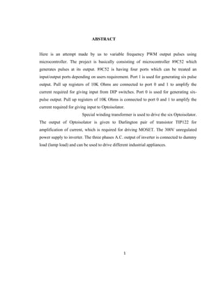
  • 21. 4.1.2 MICROCONTROLLER: 89S52 The microcontroller 89C52 consist of, Crystal oscillator, special function resistor, ALU, the stack pointer, program counter and data pointer flags and program status word, ports. CRYSTAL OSCILLATOR: The heart of microcontroller is the circuitry that generates the clock pulse, which all internal operations are synchronized. Pin XTAL1 and XTAL 2 are provided for connecting resonant network to form an oscillator. Quartz crystal and capacitor employed as shown in fig. the crystal frequency is the basic internal clock frequency for microcontroller. The microcontroller can permit 1MHZ to 21
  • 22. 16MHZ crystal. We have used 12MHZ crystal. We used 12 MHz crystal which yields the convenient is 33 Pico farad Special function Register: The microcontroller operations that do not use internal 128 byte RAM addresses from 00H to 7FH are done by a group of specific internal register, which called as Special Function Register, which can be addressed from 80H to FFH. Some SFRs are also bit addressable. This feature allows programmer to change only what needs to be altered leaving SFRs bit to bit unchanged. ALU: The ALU performs arithmetical operation and logical function. The arithmetic unit bitwise fundamental arithmetic operation such as addition and subtraction and the logical unit performs logical operation such as compliment, AND, OR, EXOR. As well as rotate and clear. THE STACK AND THE STACK POINTOR: The stack refers to an area of internal RAM. The 8bit stack pointer is used by the 89C52 to hold an internal RAM. The 8 bit stack; pointer register is called ‘Top of the stack’. When data is to be placed on the stack pointer register increments before storing the data is to be placed on the stack; the stack grows up as data is to be stored. As data is to be retrieved from the stack, the byte is read from the stack and then the stack pointer decrements to point to next available byte of stored data. The stack has potential to overwrite valuable data in register bank, bit addressable RAM. 22
  • 23. PROGRAM COUNTER AND DATA POINTER: The program counter and data pointer is used to hold the address of a byte in memory. Program instruction bytes fetched from location in memory that is addressed by the program counter. The program counter is fetched and many also the be altered by certain instruction. PC is the only register that does not have an internal address. FOUR WINDING TRANSFORMER A specially designed transformer in our project is the Four Winding transformer. The specialty of the transformer is that it has a single primary winding and Four secondary winding; S1, S2, S3, S4. S1, S2, S3 the first three secondary windings are of 0-12V, 150mA each but the fourth and last winding has turns which carry 0-12V and 450mA. The total voltage and current input to the primary winding is 230V, 1.5A 23
  • 24. 24
  • 25. FIG. OF OPTOISOLALOR GATE DRIVE POWER SUPPLY FIG OF OPTOISOLALOR AND SIGNAL AMLIFIER 25
  • 26. D.C. Supply to Inverter The D.C. supply to the inverter is derived from single phase 230 VA.C. Mains supply. Here in lies the beauty of the inverter; it provides total isolation of the input supply and output to the motor, allowing us to operate a three phase induction motor on a single phase supply. In system such as electrical vehicles where energy generated Is stored in large battery array, we can replace the A.C. supply- rectifier- filter assembly by a battery and battery charger assembly. Fig 3.5 Unregulated Power Supply: A single phase full bridge rectifier is used to convert the supply to D.C. with ripple. Thereafter a single capacitor filter is used to remove the ripple and obtain sufficiently smooth D.C. voltage at about 300V. This voltage is the input of inverter. 26
  • 27. Y B R MOSFET POWER INVERTER CIRCUIT N L3 L2 L1 Q6 IRF840 Q5 IRF840 Q4 IRF840 Q3 IRF840 Q2 IRF840 Q1 IRF840 +V V1 300vDC FIG. OF INVERTER CIRCUTRY FOR R LOAD The DPTR register is made up of two 8 bit register named as DPH and DPL which are used to furnish memory address for internal and external code access and external data access. 27
  • 28. OPERATION OF THREE-PHASE INDUCTION MOTOR Most induction motors in operation today are designed today are design for 3-phase source of alternating voltage. The stator comprises of three phase winding distributed in such a way that current in stator winding produces an approximately sinusoidally varying flux density around the air gap between the stator and rotor. When three temporally varying currents, shifted out of phase by 120ْ. From each other flow through three symmetrically placed windings, a radially directed air gap flux density is produced that is also sinusoidally distributed around the gap and is rotating at an angular velocity equal to angular frequency ωs of the stator current. Torque is developed when rotor speed ‘slips’ behind the synchronous speed of the stator traveling field. Fig. shows the torque- speed characteristic of an induction motor where ωs is the speed of stator field (ωs = 2 p f s) and ωr is rotor speed. 28
  • 29. Fig.Torque Speed Characteristics of an Induction Motor The difference between two is usually relatively small and is the slip speed. The solid portion of characteristics is the main region of interest where the motor is operating at rated flux and at low slip. In this region the rotor speed is approximately proportional to stator supply frequency, except at very low speeds. The operating point of motor on its torque-speed characteristics is at the intersection of the load torque line and the motor characteristics for small amount of slip and at constant air gap flux the motor torque is proportional to the slip speed. In a variable speed system the motor is operated on a series of torque speed characteristics as the applied frequency is increased. A set of characteristics for three conditions ωs1, ωs2 and ωs3. The corresponding rotors speeds are ωr1, ωr2 and ωr3. However in order that the air gap flux in the motor is maintained at it’s rated value then the applied voltage must be reduced in proportion to the applied frequency of traveling field. This condition for constant air gap flux gives the 29
  • 30. constant v/f requirement for variable speed control of A.C. induction motors. At low speeds this requirement may be modified by voltage boosting the supply to motor in order to overcome the increase proportion ‘IR’ voltage drop in the motor windings which occurs at low speed. Squirrel cage motors are widely used type of induction motors. We have used one such motor in our project. The rotor in such motor is made up of aluminum rods cast into the slots in outer periphery of the rotor. Cast aluminum end rings (which can also be designed to behave as fans) are used to short the aluminum bars at the both ends of the rotor. For larger squirrel cage motor, the aluminum rings are replaced by copper ones. 4.3 LAYOUT MOSFET POWER INVERTER 30
  • 31. Three Phase Appliance Protector Automatic Phase Selector Circuit Unregulated Power Supply To Inverter Circuit Opto-isolator And Signal Amplifier 31
  • 34. 5.1 Testing Procedure. 5.1 TESTING PROCEDURE OF PROJECT: The working of the project is a two mode process. When all the three phases are present/ live then the 4 pole 3 way relay directs the supply directly to the three phase load (here 3 phase load bank). Then directly the load works i.e. all the lamps lights. But, at the instance of removal/ failure of any of the phase of supply, then project circuitry comes into picture. When any of phase fails, then the supply is diverted towards the selector circuitry via 12 v SPDT (single pole double throw) relay. The RYB indicator show the failure of any of phase by switching off of that particular colour LED. Here, the selector circuit selects one live phase, then converts to two via line connector in selector, this supply is further provided to the terminal of relay (4 pole 3 way). Then all the three phases via preventer circuit, is given to the relay, then it is given to rectification circuit. The rectification circuit consists of bridge rectifier circuit. The rectifier further provides 300 v DC un-regulated supply to the MOSFET controlled inverter circuitry. This all above mentioned circuit comes under Power circuit, analogously control circuit works by giving the pulses to the base of the MOSFET controlled inverter, this constitutes PWM inverter circuitry. The trail of pulses can be controlled by the DIP switches, which acts as the input to the microcontroller 89c52. The output of microcontroller is a six pulse output, this output of the microcontroller is very small, this signal is now transmitted via opto-isolator, hence it requires amplification. The work of signal amplification is done by the signal amplifier, i.e. the Darlington pair of transistor, this signals are further provided to the base of MOSFET. A delay pot is provided in the preventer circuit, through which we can change the delay angle of the waveform, simply we can change the frequency by this from 10 hz to 100 hz. Of input to the load. Thus is working of the project. 34
  • 35. Chapter 6 ADVANTAGES, DISADVANTAGES AND APPLICATIONS 35
  • 36. 6.1 Advantages. 6.2 Disadvantages. 6.3 Applications. 6.1 ADVANTAGES: - Auto change of switch with event of failure of any 1 phase. - We can appropriately get rid of Single phasing phenomenon for any 3 phase industrial load. - Detection of phase failure & so also the supply is continued to the three phase load ,in a case when alternate source of supply is not present - Supply is kept constant even after phase failure take place after certain time lag. - Also provides protection to 3 phase appliances, from flow of erratic currents due to failure of corresponding phases. - Three phase supply loads like motors can be operated showing all its speed – torque characterstics. - Variable output frequency from 10Hz to 100Hz. - Auto change OF switch with FAILURE of 2 phase. - Speed of motor can be varied by varying frequency (Ns=(120f)/p) as N=Ns(1-s)) - DC to AC generator. 36
  • 37. 6.2 DISADVANTAGES: - Auto change of switch cannot happen with the failure of any two phase, becomes in operational with failure of two phase failure. - MOSFET limitations. - Use of 3-pole 3-way relay or 4-pole 4-way contactor. 6.3 APPLICATIONS: - This project can be used in areas like house, industries like chemical plant etc. - The application circuit can be changed to control various home appliances or industries in three phase power supply is used and much more. - All the number of applications can be increased with very minor changes in applications given as follows: 1. Suger Industries 2. In spinning and turning jobs 3. Metal working Industries. 4. Production industries. 5. Rolling Mills. 6. Saw mills. 37
  • 38. 7. Elevators. 8. For controlling similar applications in industries. Chapter 7 CONCLUSION 7.1 Conclusion. 7.1 CONCLUSION: Hence we conclude that single phasing phenomenon is effectively avoided in this project. The failure of phase can be easily traced and be converted in two phases so as to resume the supply easily, with adjustable time span, so as to avoid the flow of erratic current which would damage the motor winding causing it’s heating and permanent failure. 38
  • 39. Chapter 8 COMPONENT COSTING 8.1 Component Costing. 7.1 COMPONENT COSTING: Here we are presenting the approximate cost of our project. 39
  • 40. Table of Components Costing 40 Sr No Component Rating Qty Cost Rs 1. Transistor TIP122 06 150/- 2. MOSET IRF840 06 400/- 3. 4 winding transformer 230V/0-12V 01 1450/- 4. 4 pole 4way 230v ac relay 4 pole 4way -230 ac relay 01 350/- 5. IC 7805 Vout= 5V constant 01 15/- 6. Microcontroller IC 89C52 01 145/- 7. DIP switches 8 pin 01 45/- 8. Batten Holder 04 60/- 9. Heat Sinks 5AMP K1/2 06 250/- 10. 12 V SPDT Relay 04 100/- 11. Single side copper clad 1X1 02 450/- 12. Wooden board 01 550/- 13. Solder Metal 150 GM 250/- 14. Other components 2500/- 15. PCB,Wires, Connectors, Socket & etc. 2000/- 16. Programming 2000/- 17. Contingencies Charges 15 % 1607 17. Total 12322/-
  • 41. Chapter 9 BIBLIOGRAPHY 9.1 Internet reference 9.2 Bibliography 8.1.1 INTERNET REFERENCES: - www.ieeexplore.ieee.org/search/freesearchresult.jsp?queryText=(single-phase-to- ground%20fault%20faultfeeder %20)&poenedRefinements=*&rowsperpage=10&pagenumber=1&resultAction= ROWS_PER_PAGE - www.americanarotary.com/products/phase-converters 41
  • 42. - www.slideshare.net/ieee4mybusinessonly/automatic-active-phase-selector-for- single-phase-load-from-three-phase-supply-using-microcontroller-1 - www.automationdirect.com/adc/overview/catalog/relays_-z- _timers/motor_control_relays - www.phaseperfect.com - www.phoenixphaseconverters.com - www.industrialphaseconverters.com - www.phaseconverters.com - www.metalwebnews.com - www.grainger.com - www.kayind.com/products_application/rotary_phase.html - www.phase-a-matic.com - www.youtube.com - www.wikipedia.com - www.southern-convertors.com - www.mycollegeproject.com - www.google.com 8.1.2 BIBLIOGRAPHY: 42
  • 43. - “FUNDAMENTALS OF ELECTRICAL DRIVES” by GOPAL K. DUBEY ,2ND EDITION (NAROSA PUBLISHING HOUSE) - “POWER ELECTRONICS” by DR. P.S. BIMBHRA (KHANNA PUBLISHERS, NEW DELHI). - “POWER ELCTRONICS” by MUHAMMED H. RASHID, 3RD EDITION , (PRINTICE HILL INC. NEW JERSEY). - “POWER ELECTRONICS” by P.C. SEN, (TATA MCGRAW –HILL PUBLICATION COMPANY LIMITED COMPANY, NEW DELHI) - MAGAZINE “ ELECTRONICS FOR YOU”. - tie.ieee-ies.org/abs/54.html. 43