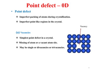
[1] Crystal defects are irregularities in the structure of a crystal that arise from imperfect packing of atoms. There are several types of crystal defects including point defects, line defects, surface defects, and volume defects.
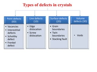
[2] Point defects are zero-dimensional and include vacancies, interstitial defects, Schottky defects, and Frenkel defects. Line defects are one-dimensional and include edge and screw dislocations. Surface defects are two-dimensional and include grain boundaries, twin boundaries, and stacking faults. Volume defects are three-dimensional voids or non-crystalline regions within the crystal structure.