Analysis of Energy Transfer in Radial and Axial Turbo Machines
•
0 likes•245 views

This document provides information about a course on turbo machines taught by Mr. Thanmay J. S. at VVIET Mysore. The course aims to analyze the energy transfer in radial and axial flow turbo machines using the degree of reaction and utilization factor. It covers general analysis of radial flow compressors and pumps, including velocity triangles and expressions for power, degree of reaction, and the effect of blade discharge angle on performance. It also discusses general analysis of axial flow pumps and compressors, and expressions for degree of reaction and utilization factor in axial flow turbines.

Recommended
More Related Content
What's hot
What's hot (20)
Similar to Analysis of Energy Transfer in Radial and Axial Turbo Machines
Similar to Analysis of Energy Transfer in Radial and Axial Turbo Machines (20)
More from THANMAY JS
More from THANMAY JS (20)
Recently uploaded
Recently uploaded (20)
Analysis of Energy Transfer in Radial and Axial Turbo Machines
- 1. Asst Proff Mr THANMAY J S, Department of Mechanical Engineering VVIET Mysore Page 1 Turbo Machines 18ME54 Course Coordinator Mr. THANMAY J. S Assistant Professor Department of Mechanical Engineering VVIET Mysore Module 02: General Analysis of Turbo machines Course Learning Objectives Analyze the energy transfer in Radial and Axial flow Turbo machine with degree of reaction and utilization factor Course Outcomes At the end of the course the student will be able to analyze the energy transfer in Turbo machine with degree of reaction and utilization factor for Radial and Axial flow type Turbo Machines.
- 2. Asst Proff Mr THANMAY J S, Department of Mechanical Engineering VVIET Mysore Page 2 Contents Modal 02: Question Number 4 a & 4 b General Analysis of Turbo machines i. Radial flow compressors and pumps – general analysis, ii. Effect of blade discharge angle on energy transfer iii. Expression for degree of reaction, iv. Effect of blade discharge angle on degree of reaction, v. Effect of blade discharge angle on performance, vi. General analysis of axial flow pumps and compressors, vii. Expression for degree of reaction and Utilization factor in Axial Flow Turbine viii. Derivation of General Equations Previous Year Question papers
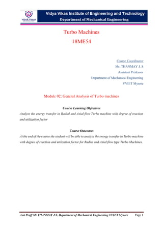
- 3. Asst Proff Mr THANMAY J S, Department of Mechanical Engineering VVIET Mysore Page 3 i. Radial flow compressors and pumps – general analysis In a radial flow machine, the two ends of the rotor blade have different linear velocities. The velocity triangles are constructed with these blade velocities as the bases. In general, the velocity triangle at the smaller radius is made up of lower velocities and that at the larger radius is made up of higher velocities. When U is small, V and Vr are also comparatively small; when U is large, V and Vr are also large. This is how the pumps and compressors are evolved with radially outward flow, with higher energy at the outlet, at the outer radius. For the same reason, the radial flow turbines are inward flow turbines, with discharge velocities of smaller magnitudes and therefore with lower values of exit losses. General Velocity Triangle Radial Flow Machines:(Centrifugal Pumps, Centrifugal Blowers and Centrifugal Compressors) Radial flow compressors and pumps are radial outward flow turbomachines, here fluid flows across the rotor blades radially from inner radius (hub radius) to outer radius (tip radius) of the rotor. Therefore radial compressors and pumps are also known as centrifugal turbomachines. The velocity triangles for the blade of an impeller of a radially outward flow machine are generally of the form as shown in figure below. (The variations from this general form may be considered step-by- step.) The absolute fluid velocity (𝑽𝟏) at the inlet is shown at (𝜶𝟏 = 𝟗𝟎°) o to the blade velocity(𝑼𝟏). In compressors or pumps of smaller sizes, guide vanes are not present to direct the fluid into the impeller at any particular angle. Hence, the fluid enters the impeller in a radial direction, giving rise to (𝑽𝒖𝟏 = 𝟎) . Since the fluid enters and leaves the rotor at different radius (𝑼𝟏 ≠ 𝑼𝟐 𝒂𝒏𝒅 𝑼𝟐 > 𝑽𝒖𝟐). In centrifugal compressor or pump usually the absolute velocity at the entry has no tangential component. Velocity Triangle for Radial Flow Compressor and Pump Radial Flow Compressors and Pumps: (Power Absorbing Turbo Machines) 𝐁𝐲 𝐄𝐮𝐥𝐞𝐫’𝐬 𝐓𝐮𝐫𝐛𝐢𝐧𝐞 𝐄𝐪𝐮𝐚𝐭𝐢𝐨𝐧 𝑷 = (𝑽𝒖𝟐. 𝑼𝟐 − 𝑽𝒖𝟏. 𝑼𝟏) 𝒃𝒖𝒕 𝑽𝒖𝟏 = 𝟎 ∴ 𝑃 = (𝑉𝑢2. 𝑈2) 𝑤𝑒 𝑘𝑛𝑜𝑤 𝑡ℎ𝑎𝑡 𝑋 = 𝑈2 − 𝑉𝑢2 𝐶𝑜𝑡 𝛽2 = 𝑋 𝑉𝑓2 ≫ 𝑿 = 𝑽𝒇𝟐 𝑪𝒐𝒕 𝜷𝟐 𝑇ℎ𝑒𝑛 𝑉𝑢2 = 𝑈2 − 𝑉𝑓2 𝐶𝑜𝑡 𝛽2 ∴ 𝑃 = (𝑉𝑢2. 𝑈2) 𝑐𝑎𝑛 𝑏𝑒 𝑤𝑟𝑖𝑡𝑡𝑒𝑛 𝑎𝑠 𝑷 = 𝑼𝟐(𝑼𝟐 − 𝑽𝒇𝟐 𝑪𝒐𝒕 𝜷𝟐) Or 𝑷 = (𝑼𝟐 𝟐 − 𝑼𝟐 . 𝑽𝒇𝟐 𝑪𝒐𝒕 𝜷𝟐)
- 4. Asst Proff Mr THANMAY J S, Department of Mechanical Engineering VVIET Mysore Page 4 ii. Effect of blade discharge angle on energy transfer a) When β2 is less than 90o , that is, when the blades are bent backward to the direction of rotation of the rotor, the slope of the line is negative. As the flow rate increases, Vf2 increases, and along with it, Vu2 decreases. Consequently, the specific work (or head) reduces as the flow rate is increased. b) When β2 is equal to 90o , the variation in the flow rate or the variation in Vf2 does not affect Vu2. The specific work (or head) remains constant. c) When β2 is more than 90o , that is, when the blades are bent forward, the slope of the line is positive. As the flow rate is increased, Vu2 also increases. Therefore, the specific work (or head) also increases. iii. Expression for Degree of Reaction 𝑏𝑢𝑡 𝑎𝑐𝑐𝑜𝑟𝑑𝑖𝑛𝑔 𝑡𝑜 𝐼𝑛𝑙𝑒𝑡 𝐶𝑜𝑛𝑑𝑖𝑡𝑖𝑜𝑛 𝑉1 = 𝑉 𝑓1 𝑠𝑜 𝑉1 2 = 𝑉 𝑓1 2 = 𝑉 𝑓2 2 𝑎𝑛𝑑 𝑓𝑜𝑟 𝑂𝑢𝑡𝑙𝑒𝑡 𝑉2 2 = 𝑉𝑈2 2 + 𝑉 𝑓2 2 ∴ 𝑅 = 𝑈2 𝑉𝑈2 − ( 𝑉𝑈2 2 + 𝑉𝑓2 2 − 𝑉𝑓1 2 ) 2 𝑈2 𝑉𝑈2 = 𝑈2 𝑉𝑈2 − ( 𝑉𝑈2 2 + 𝑉𝑓2 2 − 𝑉𝑓1 2 ) 2𝑈2 𝑉𝑈2 ∴ 𝑹 = 𝟏 − ( 𝑽𝑼 𝟐 𝟐𝑼𝟐 )
- 5. Asst Proff Mr THANMAY J S, Department of Mechanical Engineering VVIET Mysore Page 5 iv. Effect of blade discharge angle on degree of reaction, 𝑤𝑒 𝑘𝑛𝑜𝑤 𝑡ℎ𝑎𝑡 𝐷𝑒𝑔𝑟𝑒𝑒 𝑜𝑓 𝑅𝑒𝑎𝑐𝑡𝑖𝑜𝑛 𝑅 = 1 − ( 𝑉𝑈2 2𝑈2 ) 𝑓𝑜𝑟 𝑅𝑎𝑑𝑖𝑎𝑙 𝐹𝑙𝑜𝑤 𝑇𝑢𝑟𝑏𝑜 𝑀𝑎𝑐ℎ𝑖𝑛𝑒𝑠 𝑏𝑢𝑡 𝑎𝑐𝑐𝑜𝑟𝑑𝑖𝑛𝑔 𝑡𝑜 𝑉𝑒𝑙𝑜𝑐𝑖𝑡𝑦 𝑡𝑟𝑖𝑎𝑛𝑔𝑙𝑒 𝑽𝑼𝟐 = 𝑼𝟐 − 𝑿 𝑤ℎ𝑒𝑟𝑒 cot(𝛽2) = ( 𝑐𝑜𝑠 𝑠𝑖𝑛 ) = 𝐴𝑑𝑗𝑎𝑐𝑒𝑛𝑡 𝑠𝑖𝑑𝑒 𝑂𝑝𝑝𝑖𝑠𝑖𝑡𝑒 𝑠𝑖𝑑𝑒 = 𝑋 𝑉𝑓2 ∴ 𝑿 = 𝑽𝒇𝟐 𝐜𝐨𝐭(𝜷𝟐) 𝑠𝑜, 𝑉𝑈2 = 𝑈2 − 𝑋 ≫ 𝑽𝑼𝟐 = 𝑼𝟐 − 𝑽𝒇𝟐 𝐜𝐨𝐭(𝜷𝟐) 𝑒𝑔𝑟𝑒𝑒 𝑜𝑓 𝑅𝑒𝑎𝑐𝑡𝑖𝑜𝑛 𝑅 = 1 − ( 𝑉𝑈2 2𝑈2 ) ≫ 𝑅 = 1 − ( 𝑈2 − 𝑉𝑓2 cot(𝛽2) 2𝑈2 ) 𝑏𝑦 𝑟𝑒𝑠𝑜𝑙𝑣𝑖𝑛𝑔 𝑤𝑒 𝑔𝑒𝑡 𝑹 = 𝟏 𝟐 [𝟏 + ( 𝑽𝒇𝟐 𝟐𝑼𝟐 )𝐜𝐨𝐭(𝜷𝟐)] 𝑇ℎ𝑖𝑠 𝑟𝑒𝑠𝑢𝑙𝑡 𝑖𝑠 𝑎𝑝𝑝𝑙𝑖𝑐𝑎𝑏𝑙𝑒 𝑓𝑜𝑟 𝛼1 = 90° 𝑠𝑜 𝑡ℎ𝑎𝑡 𝑉1 = 𝐹2 = 𝑈1 𝑎𝑛𝑑 𝑉𝑢1 = 0 a) When β2, in the above conditions, becomes equal to 158.2o , the degree of reaction reduces to zero, the machine becomes impulse type, and the centrifugal head balances the relative velocity head. (R = 0 at β2 =158.2o ) b) If the reference values of β1 and D2/D1 were chosen then the nature of variation of R would be the same, but the values would be different (W = 0 at β2 = 26.5o ; R = (2 + cot β2)/4. v. Effect of blade discharge angle on performance, 𝑷 = (𝑼𝟐 𝟐 − 𝑼𝟐 . 𝑽𝒇𝟐 𝑪𝒐𝒕 𝜷𝟐) In a Power Absorbing Turbo Machines like a pump, a blower, or a compressor is usually run by a motor of constant speed N, Hence, 𝑼𝟐 = 𝝅𝑫𝑵 𝟔𝟎 is also a constant. Further(𝑽𝒇𝟐), the flow component, can be written as( 𝑸 𝑨𝟐 ), where𝑨𝟐is the exit area of the impeller and (𝑸) is the volume flow rate. This results 𝑷 = (𝑼𝟐 𝟐 − 𝑼𝟐 . 𝑽𝒇𝟐 𝑪𝒐𝒕 𝜷𝟐) ≫ (𝑼𝟐 𝟐 − 𝑼𝟐 . ( 𝑸 𝑨𝟐 ) 𝑪𝒐𝒕 𝜷𝟐) = (𝑪𝟏 − 𝑪𝟐. 𝑸) ≫ Where 𝑪𝟏 = 𝑼𝟐 𝟐 and𝑪𝟐 = ( 𝑼𝟐 𝑨𝟐 ) 𝑪𝒐𝒕 𝜷𝟐. 𝑷 = (𝑪𝟏 − 𝑪𝟐. 𝑸) The performance of a machine is the totality of the specific work or energy transfer, the reaction, the power consumption, the efficiency, and so on. Equation (𝑷) represents the energy transfer (W) in a radial flow pump or compressor. In a pump, the head developed may be written as (W/g). In a compressor, the pressure developed may be written as (W x ρ). Either way, (W) is identified as a function of the flow rate (Q).
- 6. Asst Proff Mr THANMAY J S, Department of Mechanical Engineering VVIET Mysore Page 6 The flow rate (Q) is taken as an independent variable that can be varied by the operation of a valve at the outlet. In practice, the flow rate is as per “demand” or “load.” A plot of (W) (or P or H or E to a different scale) on the base of the flow rate (Q), therefore, represents one of the important characteristics of the machine. For a given value of the flow rate, there is one more important effect of variation of the blade outlet angle. For any outlet velocity triangle, as the height of the triangle, (𝑽𝒇𝟐) remains constant, (𝑽𝒖𝟐) keeps on increasing as the blade outlet angle (𝜷𝟐) increases. This can easily be seen in Fig. 4.4. This can also be substantiated by above equation where the magnitude of (𝑷) increases as (𝜷𝟐) increases. The specific work (𝑷) will gradually reduce to zero when 𝑽𝒇𝟐 𝑪𝒐𝒕 𝜷𝟐 = 𝑼𝟐 𝒊. 𝒆., 𝑪𝒐𝒕 𝜷𝟐 = 𝑼𝟐 𝑽𝒇𝟐 Above figure shows the characteristic in the form of three lines with different slopes. The lines represent the cases of different values of the blade exit angle(𝜷𝟐). Equation (𝑷) and graph shown above are the outcome of the starting from Euler’s equation. The energy transfer, as discussed, is due to the “vane-congruent flow.” The expression for the actual energy transfer can be obtained when the factors causing the deviation from the vane- congruent flow are considered.
- 7. Asst Proff Mr THANMAY J S, Department of Mechanical Engineering VVIET Mysore Page 7 vi. General analysis of axial flow pumps and compressors, In axial flow machines, the blade velocities at the inlet and outlet are equal, 𝑼𝟏 = 𝑼𝟐 𝒂𝒏𝒅 𝑽𝒖𝟏 > 𝑼𝟏 . Therefore, the two velocity triangles have equal bases. Both the triangles can be drawn on a common base. In these kinds of machines, the flow velocity (𝑽𝒇𝟏 = 𝑽𝒇𝟐 = 𝑽𝒇) is assumed to be constant from inlet to outlet. Axial flow turbines comprise the familiar steam turbines, gas turbines etc. = Energy Equation for Axial Flow Turbo Machine Power Absorbing Turbo Machines Power Absorbing Turbo Machines 𝑷 = 𝒎(𝑽𝒖𝟐. 𝑼𝟐 − 𝑽𝒖𝟏. 𝑼𝟏) 𝑷 = 𝟏 𝟐 [(𝑽𝟐 𝟐 − 𝑽𝟏 𝟐 ) + (𝑼𝟐 𝟐 − 𝑼𝟏 𝟐 ) + (𝑽𝒓𝟐 𝟐 − 𝑽𝒓𝟏 𝟐 )] 𝒃𝒖𝒕 𝑼𝟏 = 𝑼𝟐 = 𝑼 𝒃𝒖𝒕 𝑼𝟏 = 𝑼𝟐 = 𝑼 ∴ 𝑷 = 𝑼(𝑽𝒖𝟐 − 𝑽𝒖𝟏) ∴ 𝑷 = 𝟏 𝟐 [(𝑽𝟐 𝟐 − 𝑽𝟏 𝟐 ) + (𝑽𝒓𝟐 𝟐 − 𝑽𝒓𝟏 𝟐 )] Expression for degree of reaction and Utilization factor in Axial Flow Turbine 𝑷 = 𝟏 𝟐 [(𝑽𝟐 𝟐 − 𝑽𝟏 𝟐 ) + (𝑼𝟐 𝟐 − 𝑼𝟏 𝟐 ) + (𝑽𝒓𝟐 𝟐 − 𝑽𝒓𝟏 𝟐 )] 𝒃𝒖𝒕 𝑼𝟏 = 𝑼𝟐 = 𝑼 ∴ 𝑷 = 𝟏 𝟐 [(𝑽𝟐 𝟐 − 𝑽𝟏 𝟐 ) + (𝑽𝒓𝟐 𝟐 − 𝑽𝒓𝟏 𝟐 )] 𝒘𝒆 𝒌𝒏𝒐𝒘 𝒕𝒉𝒂𝒕 𝑫𝒆𝒈𝒓𝒆𝒆 𝒐𝒇 𝑹𝒆𝒂𝒄𝒕𝒊𝒐𝒏 (𝑹) = 𝑻𝒐𝒕𝒂𝒍 𝑾𝒐𝒓𝒌−𝑲𝒊𝒏𝒆𝒕𝒊𝒄 𝑪𝒐𝒎𝒑𝒐𝒏𝒆𝒏𝒕 𝑻𝒐𝒕𝒂𝒍 𝑾𝒐𝒓𝒌 = 𝑷−𝑲𝑬 𝑷 = 𝟏 − 𝑲𝑬 𝑷 (𝑹) = 𝟏 𝟐 (𝑽𝟐 𝟐 − 𝑽𝟏 𝟐 ) + 𝟏 𝟐 (𝑽𝒓𝟐 𝟐 − 𝑽𝒓𝟏 𝟐 ) − 𝟏 𝟐 (𝑽𝟐 𝟐 − 𝑽𝟏 𝟐 ) 𝟏 𝟐 (𝑽𝟐 𝟐 − 𝑽𝟏 𝟐 ) + (𝑽𝒓𝟐 𝟐 − 𝑽𝒓𝟏 𝟐 ) (𝑹) = 𝟏 𝟐 (𝑽𝒓𝟐 𝟐 − 𝑽𝒓𝟏 𝟐 ) 𝟏 𝟐 (𝑽𝟐 𝟐 − 𝑽𝟏 𝟐 ) + (𝑽𝒓𝟐 𝟐 − 𝑽𝒓𝟏 𝟐 ) 𝒐𝒓 (𝑽𝒓𝟐 𝟐 − 𝑽𝒓𝟏 𝟐 ) (𝑽𝟐 𝟐 − 𝑽𝟏 𝟐 ) + (𝑽𝒓𝟐 𝟐 − 𝑽𝒓𝟏 𝟐 ) 𝒐𝒓 𝟏 𝟐 (𝑽𝒓𝟐 𝟐 − 𝑽𝒓𝟏 𝟐 ) 𝑷 𝒊𝒇 𝑽𝒓𝟐 𝟐 = 𝑽𝒓𝟏 𝟐 𝒕𝒉𝒆𝒏 𝑹 = 𝟏 𝟐 (𝑽𝒓𝟐 𝟐 − 𝑽𝒓𝟏 𝟐 ) 𝑷 = 𝟎 𝒘𝒆 𝑲𝒏𝒐𝒘 𝒕𝒉𝒂𝒕 𝑼𝒕𝒊𝒍𝒊𝒛𝒂𝒕𝒊𝒐𝒏 𝑭𝒂𝒄𝒕𝒐𝒓 (𝝐) = (𝑽𝟏 𝟐 − 𝑽𝟐 𝟐 ) + (𝑼𝟏 𝟐 − 𝑼𝟐 𝟐 ) + (𝑽𝒓𝟏 𝟐 − 𝑽𝒓𝟐 𝟐 ) (𝑽𝟏 𝟐 ) + (𝑼𝟏 𝟐 − 𝑼𝟐 𝟐 ) + (𝑽𝒓𝟏 𝟐 − 𝑽𝒓𝟐 𝟐 ) 𝒃𝒖𝒕 𝑼𝟏 = 𝑼𝟐 = 𝑼 ∴ 𝑼𝒕𝒊𝒍𝒊𝒛𝒂𝒕𝒊𝒐𝒏 𝑭𝒂𝒄𝒕𝒐𝒓 (𝝐) = (𝑽𝟏 𝟐 − 𝑽𝟐 𝟐 ) + (𝑽𝒓𝟏 𝟐 − 𝑽𝒓𝟐 𝟐 ) (𝑽𝟏 𝟐 ) + (𝑽𝒓𝟏 𝟐 − 𝑽𝒓𝟐 𝟐 )
- 8. Asst Proff Mr THANMAY J S, Department of Mechanical Engineering VVIET Mysore Page 8 Derivation of General Equations:
- 9. Asst Proff Mr THANMAY J S, Department of Mechanical Engineering VVIET Mysore Page 9
- 10. Asst Proff Mr THANMAY J S, Department of Mechanical Engineering VVIET Mysore Page 10
- 11. Asst Proff Mr THANMAY J S, Department of Mechanical Engineering VVIET Mysore Page 11
- 12. Asst Proff Mr THANMAY J S, Department of Mechanical Engineering VVIET Mysore Page 12 Previous Year Question papers Modal Question Paper 01 18ME54 4 a) Obtain an expression for the degree of reaction of axial flow compressor in terms of rotor blade angles, axial velocity and blade speed. Assume axial velocity remains constant. 8 𝑹 = 𝟏 𝟐 [𝟏 + ( 𝑽𝒇𝟐 𝟐𝑼𝟐 )𝐜𝐨𝐭(𝜷𝟐)] 𝑷𝒂𝒈𝒆 𝑵𝒐 𝟓 b) At a stage of Impulse Turbine the mean blade diameter is 0.75m and its rotational speed is 3500 rpm. The absolute velocity of the fluid discharging from a nozzle inclined at 20° to the plane of the wheel is 275 m/s. If the utilization factor is 0.9 and the relative velocity of the fluid at the rotor exit is 0.9 times that at the inlet, find the inlet rotor angles. Also find the power output from the stage for a mass flow rate of 2 kg/s and the axial thrust on the shaft. 12 To solve this problem there are three assumptions which can be used. Chose the Method whichever is suitable Impulse Turbine is Axial flow turbine example: Delaval turbine 𝐷(𝑚𝑒𝑎𝑛) = 0.75𝑚; 𝑁 = 3500𝑟𝑝𝑚 ∴ 𝑈 = 𝜋𝐷𝑁 60 = 𝜋 × 0.75 × 3500 60 = 137.44 𝑚 𝑠 𝑼𝟏 = 𝑼𝟐 = 𝑼 = 𝟏𝟑𝟕. 𝟒𝟒 𝒎/𝒔 𝑽𝟏 = 𝟐𝟕𝟓 𝒎 𝒔 𝒂𝒕 𝜶𝟏 = 𝟐𝟎° & 𝝐 = 𝟎. 𝟗 𝒂𝒏𝒅 𝑽𝒓𝟐 = 𝟎. 𝟗𝑽𝒓𝟏 𝒇𝒊𝒏𝒅 𝜷𝟏 =? ; 𝑷 =? 𝒘𝒉𝒆𝒏 𝒎 = 𝟐𝒌𝒈 𝒔 & 𝑭𝒂 =? 𝒔𝒊𝒏𝜶𝟏 = 𝑽𝒇𝟏 𝑽𝟏 𝒂𝒏𝒅 𝒄𝒐𝒔𝜶𝟏 = 𝑽𝒖𝟏 𝑽𝟏 𝑠𝑖𝑛𝛼1 = 𝑉𝑓1 𝑉1 ≫ 𝑉𝑓1 = 𝑉1 × 𝑠𝑖𝑛𝛼1 𝑉𝑓1 = 275 × 𝑠𝑖𝑛20 = 94.05𝑚/𝑠 𝑽𝒇𝟏 = 𝟗𝟒. 𝟎𝟓 𝒎/𝒔 𝑐𝑜𝑠𝛼1 = 𝑉𝑢1 𝑉1 ≫ 𝑉𝑢1 = 𝑉1 × 𝑐𝑜𝑠𝛼1 = 275 × 𝑐𝑜𝑠20 = 258.41𝑚/𝑠 𝑽𝒖𝟏 = 𝟐𝟓𝟖. 𝟒𝟏 𝒎/𝒔 𝑿𝟏 = 𝑽𝒖𝟏 − 𝑼 = 𝟐𝟓𝟖. 𝟒𝟏 − 𝟏𝟑𝟕. 𝟒𝟒 = 𝟏𝟐𝟎. 𝟗𝟕𝒎/𝒔 𝒕𝒂𝒏𝜷𝟏 = 𝑽𝒇𝟏 𝑿𝟏 ≫ 𝜷𝟏 = 𝒕𝒂𝒏−𝟏 ( 𝑽𝒇𝟏 𝑿𝟏 ) = 𝟑𝟕. 𝟖𝟔° ≈ 𝟑𝟖° 𝑽𝒓𝟏 = √𝑽𝒇𝟏𝟐 + 𝑿𝟏𝟐 = √𝟗𝟒. 𝟎𝟓𝟐 + 𝟏𝟐𝟎. 𝟗𝟕𝟐 = 𝟏𝟓𝟑. 𝟐𝟐𝒎/𝒔 𝑽𝒓𝟐 = 𝟎. 𝟗𝑽𝒓𝟏 = 𝟎. 𝟗 × 𝟏𝟓𝟑. 𝟐𝟐 𝑽𝒓𝟐 = 𝟏𝟑𝟕. 𝟗𝟎 𝒎/𝒔 𝑼 = 𝟏𝟑𝟕. 𝟒𝟒 𝒎 𝒔 ; 𝑽𝒓𝟏 = 𝟏𝟓𝟑. 𝟐𝟐 𝒎 𝒔 ; 𝑽𝒓𝟐 = 𝟏𝟑𝟕. 𝟗𝟎 𝒎 𝒔 ; 𝑽𝒇𝟏 = 𝟗𝟒. 𝟎𝟓 𝒎 𝒔 ; 𝑽𝟏 = 𝟐𝟕𝟓 𝒎 𝒔 ; 𝑽𝒖𝟏 = 𝟐𝟓𝟖. 𝟒𝟏 𝒎/𝒔 𝑉𝑟2 = 0.9𝑉𝑟1 𝑠𝑜 𝑉𝑟2 = 𝑉𝑟1 𝑐𝑎𝑛𝑛𝑜𝑡 𝑏𝑒 𝑎𝑠𝑠𝑢𝑚𝑒𝑑 Method01: 𝒂𝒔𝒔𝒖𝒎𝒆 𝑽𝒇𝟏 = 𝑽𝒇𝟐 Method 02: 𝒊𝒇 𝒘𝒆 𝒂𝒔𝒔𝒖𝒎𝒆 𝜷𝟏 = 𝜷𝟐 = 𝟑𝟖° (𝒃𝒍𝒂𝒅𝒆𝒔 𝒂𝒓𝒆 𝒆𝒒𝒖𝒊𝒂𝒏𝒈𝒖𝒍𝒂𝒓) 𝒔𝒊𝒏𝜷𝟐 = 𝑽𝒇𝟐 𝑽𝒓𝟐 = 𝟗𝟒. 𝟎𝟓 𝟏𝟑𝟕. 𝟗𝟎 = 𝟎. 𝟔𝟖 ≫ 𝜷𝟐 = 𝒔𝒊𝒏−𝟏(𝟎. 𝟔𝟖) = 𝟒𝟑° 𝒔𝒊𝒏𝜷𝟐 = 𝑽𝒇𝟐 𝑽𝒓𝟐 ≫ 𝑽𝒇𝟐 = 𝑽𝒓𝟐 × 𝒔𝒊𝒏𝜷𝟐 𝑽𝒇𝟐 = 𝟏𝟑𝟕. 𝟗𝟎 × 𝒔𝒊𝒏𝟑𝟖 = 𝟖𝟒. 𝟖𝟗 𝑽𝒇𝟐 = 𝟖𝟒. 𝟖𝟗𝒎/𝒔 𝒄𝒐𝒔𝜷𝟐 = 𝑿𝟐 𝑽𝒓𝟐 ≫ 𝑿𝟐 = 𝑽𝒓𝟐 × 𝒄𝒐𝒔𝜷𝟐 𝑿𝟐 = 𝟏𝟑𝟕. 𝟗𝟏 × 𝒄𝒐𝒔𝟒𝟑 = 𝟏𝟎𝟎. 𝟖𝟓 𝒎/𝒔 𝑿𝟐 = 𝑽𝒓𝟐 × 𝒄𝒐𝒔𝜷𝟐 < 𝑼 𝒔𝒐 𝒏𝒆𝒈𝒂𝒕𝒊𝒗𝒆 𝒂𝒏𝒔𝒘𝒆𝒓 𝑽𝒖𝟐 = 𝑿𝟐 − 𝑼 = 𝟏𝟎𝟎. 𝟖𝟓 − 𝟏𝟑𝟕. 𝟒𝟒 𝑽𝒖𝟐 = −𝟑𝟔. 𝟓𝟗 𝒎/𝒔 𝒄𝒐𝒔𝜷𝟐 = 𝑿𝟐 𝑽𝒓𝟐 ≫ 𝑿𝟐 = 𝑽𝒓𝟐 × 𝒄𝒐𝒔𝜷𝟐 𝑿𝟐 = 𝟏𝟑𝟕. 𝟗𝟎 × 𝒄𝒐𝒔𝟑𝟖 = 𝟏𝟎𝟖. 𝟔𝟔𝒎/𝒔 𝑿𝟐 = 𝑽𝒓𝟐 × 𝒄𝒐𝒔𝜷𝟐 < 𝑼 𝒔𝒐 𝒏𝒆𝒈𝒂𝒕𝒊𝒗𝒆 𝒂𝒏𝒔𝒘𝒆𝒓 𝑽𝒖𝟐 = 𝑿𝟐 − 𝑼 = 𝟏𝟎𝟖. 𝟔𝟔 − 𝟏𝟑𝟕. 𝟒𝟒 𝑽𝒖𝟐 = −𝟐𝟖. 𝟕𝟕𝒎/𝒔 𝑷 𝒎 = 𝑼(𝑽𝒖𝟏 − 𝑽𝒖𝟐) = 𝟏𝟑𝟕. 𝟒𝟒(𝟐𝟓𝟖. 𝟒𝟏 − (−𝟑𝟔. 𝟓𝟗)) 𝑷 𝒎 = 𝟒𝟎𝟓𝟒𝟒. 𝟖 𝑾 𝑵𝒐𝒕𝒆: 𝒎 = 𝟐𝒌𝒈 𝒏𝒐𝒕 𝒖𝒔𝒆𝒅 𝑷 𝒎 = 𝑼(𝑽𝒖𝟏 − 𝑽𝒖𝟐) = 𝟏𝟑𝟕. 𝟒𝟒(𝟐𝟓𝟖. 𝟒𝟏 − (−𝟐𝟖. 𝟕𝟕)) 𝑷 𝒎 = 𝟑𝟗𝟒𝟕𝟎. 𝟎𝟏 𝑾 𝑵𝒐𝒕𝒆: 𝒎 = 𝟐𝒌𝒈 𝒏𝒐𝒕 𝒖𝒔𝒆𝒅 𝑽𝟐 = √𝑽𝒇𝟐𝟐 + 𝑽𝒖𝟐𝟐 = √𝟗𝟒. 𝟎𝟓𝟐 + (−𝟑𝟔. 𝟓𝟗𝟐) 𝑽𝟐 = 𝟏𝟎𝟎. 𝟗𝟏 𝒎 𝒔 & 𝑽𝟏 = 𝟐𝟕𝟓 𝒎 𝒔 𝑽𝟐 = √𝑽𝒇𝟐𝟐 + 𝑽𝒖𝟐𝟐 = √𝟖𝟒. 𝟖𝟗𝟐 + (−𝟐𝟖. 𝟕𝟕𝟐) 𝑽𝟐 = 𝟖𝟗. 𝟔𝟑 𝒎 𝒔 & 𝑽𝟏 = 𝟐𝟕𝟓 𝒎 𝒔
- 13. Asst Proff Mr THANMAY J S, Department of Mechanical Engineering VVIET Mysore Page 13 𝑼𝒕𝒊𝒍𝒊𝒛𝒂𝒕𝒊𝒐𝒏 𝑭𝒂𝒄𝒕𝒐𝒓 (𝝐) = (𝑽𝟏 𝟐 − 𝑽𝟐 𝟐 ) (𝑽𝟏 𝟐 − 𝑹 𝑽𝟐 𝟐 ) = 𝟎. 𝟗 𝑽𝟏 𝟐 = 𝒂; 𝑽𝟐 𝟐 = 𝒃; 𝑹 = 𝒄 ≫ (𝒂 − 𝒃) (𝒂 − 𝒄 𝒃) = 𝟎. 𝟗 (𝒂 − 𝒄 𝒃) = (𝒂 − 𝒃) 𝟎. 𝟗 = 𝟕𝟐𝟕𝟏𝟑. 𝟓𝟐 (−𝒄 𝒃) = 𝟕𝟐𝟕𝟏𝟑. 𝟓𝟐 − 𝒂 = −𝟐𝟗𝟏𝟏. 𝟒𝟖 (𝒄 ) = −𝟐𝟗𝟏𝟏. 𝟒𝟖 −𝒃 = 𝟎. 𝟐𝟗𝟓𝟗 𝑹 = 𝟑𝟎% 𝒕𝒊𝒍𝒊𝒛𝒂𝒕𝒊𝒐𝒏 𝑭𝒂𝒄𝒕𝒐𝒓 (𝝐) = (𝑽𝟏 𝟐 − 𝑽𝟐 𝟐 ) (𝑽𝟏 𝟐 − 𝑹 𝑽𝟐 𝟐 ) = 𝟎. 𝟗 𝑽𝟏 𝟐 = 𝒂; 𝑽𝟐 𝟐 = 𝒃; 𝑹 = 𝒄 ≫ (𝒂 − 𝒃) (𝒂 − 𝒄 𝒃) = 𝟎. 𝟗 (𝒂 − 𝒄 𝒃) = (𝒂 − 𝒃) 𝟎. 𝟗 = 𝟕𝟓𝟏𝟎𝟏. 𝟔𝟐 (−𝒄 𝒃) = 𝟕𝟓𝟏𝟎𝟏. 𝟔𝟐 − 𝒂 = −𝟓𝟐𝟑. 𝟑𝟖 (𝒄 ) = −𝟓𝟐𝟑. 𝟑𝟖 −𝒃 = 𝟎. 𝟎𝟔𝟓𝟏𝟒 𝑹 = 𝟔. 𝟓𝟏% 𝑭 (𝒂𝒙𝒊𝒂𝒍) = 𝒎(𝑽𝒇𝟏 − 𝑽𝒇𝟐) = 𝟎 𝒂𝒔 𝑽𝒇𝟏 = 𝑽𝒇𝟐 𝑨𝒔𝒔𝒖𝒎𝒑𝒕𝒊𝒐𝒏 𝑭 (𝒂𝒙𝒊𝒂𝒍) = 𝒎(𝑽𝒇𝟏 − 𝑽𝒇𝟐) = Method 03: Assume R=50% or 0.5 𝑼𝒕𝒊𝒍𝒊𝒛𝒂𝒕𝒊𝒐𝒏 𝑭𝒂𝒄𝒕𝒐𝒓 (𝝐) = (𝑽𝟏 𝟐 − 𝑽𝟐 𝟐 ) (𝑽𝟏 𝟐 − 𝑹 𝑽𝟐 𝟐 ) = 𝟎. 𝟗 𝒘𝒆 𝒌𝒏𝒐𝒘 𝒕𝒉𝒂𝒕 𝑽𝟏 = 𝟐𝟕𝟓 𝒎 𝒔 ; 𝑹 = 𝟎. 𝟓𝟎 (𝝐) = (𝑽𝟏 𝟐 − 𝑽𝟐 𝟐 ) (𝑽𝟏 𝟐 − 𝑹 𝑽𝟐 𝟐 ) = 𝟎. 𝟗 ≫ (𝝐) = (𝒂 − 𝒃) (𝒂 − 𝑹 𝒃) = 𝟎. 𝟗 (𝒂 − 𝒃) (𝒂 − 𝟎. 𝟓𝒃) = 𝟎. 𝟗 ≫ (𝒂 − 𝒃) = 𝟎. 𝟗𝒂 − 𝟎. 𝟒𝟓𝒃 𝒂 − 𝟎. 𝟗𝒂 = 𝒃 − 𝟎. 𝟒𝟓𝒃 𝒂(𝟏 − 𝟎. 𝟗) (𝟏 − 𝟎. 𝟓) = 𝒃 = 𝑽𝟐 𝟐 = 𝑽𝟏 𝟐 (𝟏 − 𝟎. 𝟗) (𝟏 − 𝟎. 𝟓) = 𝟏𝟓𝟏𝟐𝟓 𝑽𝟐 = √𝟏𝟓𝟏𝟐𝟓 = 𝟏𝟐𝟐. 𝟗𝟖𝒎/𝒔 Modal Question Paper 02 18ME54 4 a) Prove that, with usual notations, the degree of reaction for an axial flow compressor (assuming constant velocity of flow) is given by 6 Activity Question solved in page Number 11 b) Draw the inlet and exit velocity triangles for a radial flow power absorbing turbomachine with (i) Backward curved vane (ii) Radial vane (iii) Forward vane. Assume inlet whirl velocity to be zero. Also draw the head-capacity curves for the above 3 types of vanes. 6 Page Number 04 c) A mixed flow turbine handling water operates under a static head of 65m. In a steady flow, the static pressure at the rotor inlet is 3.5 atm (gauge). The absolute velocity at the rotor inlet has no axial component and is directed at an angle of 25º to the tangent of wheel so that Vu1 is positive. The absolute velocity at exit purely axial. If the degree of reaction for the machine is 0.47 and utilization factor is 0.896, compute the tangential blade speed at inlet as well as the inlet blade angle Find also the work output per unit mass flow of water. 8
- 14. Asst Proff Mr THANMAY J S, Department of Mechanical Engineering VVIET Mysore Page 14 Modal Question Paper 01 18ME54 (2015/2016) 4 a) For an axial flow compressor, derive an expression for degree of reaction. 8 b) In a radial inward flow turbine the degree of reaction is 0.8 and the utilization factor of the runner is 0.9. The tangential speeds of the wheel at the inlet and the outlet are respectively 11m/s and 5.5m/s. Draw the velocity triangles at inlet and outlet assuming radial velocity is constant and equal to 5m/s. Flow is radial at exit. Find the power output for a volumetric flow rate of 2𝒎𝟑 of water per second. (𝟐 𝟎𝟎𝟎. 𝟎𝟎 𝐤𝐠 𝐬 ) 8 𝑫𝒆𝒈𝒓𝒆𝒆 𝒐𝒇 𝑹𝒆𝒂𝒄𝒕𝒊𝒐𝒏 (𝑹) = 𝟎. 𝟖; 𝑼𝒕𝒊𝒍𝒊𝒛𝒂𝒕𝒊𝒐𝒏 𝑭𝒂𝒄𝒕𝒐𝒓 (𝝐) = 𝟎. 𝟗 ; 𝑼𝟏 = 𝟏𝟏 𝒎 𝒔 ; 𝑼𝟐 = 𝟓. 𝟓 𝒎 𝒔 ; 𝑽𝒇𝟏 = 𝑽𝟏 = 𝟓 𝒎 𝒔 ; 𝒓𝒂𝒅𝒊𝒂𝒍 𝒐𝒖𝒕𝒍𝒆𝒕 = 𝜶𝟐 = 𝟗𝟎°; 𝑸 = 𝟐 𝒎𝟑 𝒔 𝒓𝒂𝒅𝒊𝒂𝒍 𝑰𝒏𝒍𝒆𝒕 = 𝜶𝟏 = 𝟗𝟎; 𝒓𝒂𝒅𝒊𝒂𝒍 𝒐𝒖𝒕𝒍𝒆𝒕 = 𝜶𝟐 = 𝟗𝟎 ∴ 𝑽𝒖𝟏 = 𝟎 Inlet but for outlet = Method 1 Method 2 𝑷 = 𝒎(𝑼𝟐 𝟐 − 𝑼𝟐 . 𝑽𝒇𝟐 𝑪𝒐𝒕 𝜷𝟐) 𝑷 = 𝒎(𝑼𝟐 𝟐 − 𝑼𝟐 . 𝑽𝒇𝟐 𝑪𝒐𝒕 𝜷𝟐) (𝝐) = (𝑽𝟏 𝟐−𝑽𝟐 𝟐) (𝑽𝟏 𝟐−𝑹 𝑽𝟐 𝟐) = 𝟎. 𝟗 = (𝟓𝟐−𝑽𝟐 𝟐) (𝟓𝟐−𝟎.𝟖 𝑽𝟐 𝟐) ≫ 𝑽𝟐 𝟐 = 𝟖. 𝟗𝟐𝟖𝟓 ≫ 𝑽𝟐 = 𝟐. 𝟗 = 𝑽𝒇𝟐 𝑽𝒇𝟐 = 𝟐. 𝟗 = 𝑽𝟐 assuming radial velocity is constant and equal to 5m/s. 𝑽𝒇𝟏 = 𝑽𝒇𝟐 = 𝟓𝒎/𝒔 𝒕𝒂𝒏 𝜷𝟏 = 𝑽𝟏 𝑼𝟏 = 𝟓 𝟏𝟏 𝒕𝒂𝒏 𝜷𝟐 = 𝑽𝟐 𝑼𝟐 = 𝟐.𝟗 𝟓.𝟓 𝒕𝒂𝒏 𝜷𝟏 = 𝑽𝟏 𝑼𝟏 = 𝟓 𝟏𝟏 𝒕𝒂𝒏 𝜷𝟐 = 𝑽𝟐 𝑼𝟐 = 𝟓 𝟓.𝟓 ∴ 𝜷𝟏 = 𝟐𝟒. 𝟒𝟒° ∴ 𝜷𝟐 = 𝟐𝟕. 𝟖𝟎° ∴ 𝜷𝟏 = 𝟐𝟒. 𝟒𝟒° ∴ 𝜷𝟐 = 𝟒𝟐. 𝟐𝟕° 𝑷 = 𝒎(𝑼𝟐 𝟐 − 𝑼𝟐 . 𝑽𝒇𝟐 𝑪𝒐𝒕 𝜷𝟐) 𝑷 = 𝒎(𝟓. 𝟓𝟐 − 𝟓. 𝟓 × 𝟐. 𝟗 × 𝑪𝒐𝒕 𝟐𝟕. 𝟖𝟎) 𝑷 = 𝟐𝟎𝟎𝟎(𝟓. 𝟓𝟐 − 𝟓. 𝟓 × 𝟐. 𝟗 × 𝟏. 𝟖𝟗) 𝑷 = 𝒎(𝑼𝟐 𝟐 − 𝑼𝟐 . 𝑽𝒇𝟐 𝑪𝒐𝒕 𝜷𝟐) 𝑷 = 𝒎(𝟓. 𝟓𝟐 − 𝟓. 𝟓 × 𝟓 × 𝑪𝒐𝒕 𝟒𝟐. 𝟐𝟕) 𝑷 = 𝟐𝟎𝟎𝟎(𝟓. 𝟓𝟐 − 𝟓. 𝟓 × 𝟓 × 𝟏. 𝟏𝟎) 𝑷 = 𝟐𝟎𝟎𝟎(𝟓. 𝟓𝟐 − 𝟓. 𝟓 × 𝟐. 𝟗 × 𝟏. 𝟖𝟗) 𝑷 = 𝟐𝟎𝟎𝟎(𝟑𝟎. 𝟐𝟓 − 𝟑𝟎. 𝟐𝟓) = 𝟎 𝑷 = 𝟐𝟎𝟎𝟎(𝟓. 𝟓𝟐 − 𝟓. 𝟓 × 𝟓 × 𝟏. 𝟏𝟎) 𝑷 = 𝟐𝟎𝟎𝟎(𝟑𝟎. 𝟐𝟓 − 𝟑𝟎. 𝟐𝟓) = 𝟎 Modal Question Paper 02 18ME54 (2015/2016)
- 15. Asst Proff Mr THANMAY J S, Department of Mechanical Engineering VVIET Mysore Page 15 4 a) Derive the theoretical head capacity relation in case of centrifugal pump Discuss the effect of blade angle at outlet on head. 8 b) Draw the inlet and outlet triangles for an axial flow compressor for which given (1) Degree of reaction =0.5 (2) inlet blade angle =40’ axial velocity of flow which is constant throughout = 125m/s (4) RPM =6500 (5) Radius = 0.2m. Calculate the power required in kW at an air flow rate = 1.5kg/s. Find fluid angles at inlet and outlet. Blade speed is same at exit and inlet. 8 𝑹 = 𝟎. 𝟓 𝜷𝟏 = 𝟒𝟎° 𝑽𝒇𝟏 = 𝑽𝒇𝟐 = 𝟏𝟐𝟓𝒎/𝒔 𝑵 = 𝟔𝟓𝟎𝟎𝒓𝒑𝒎 𝒓 = 𝟎. 𝟐𝒎 𝒔𝒐 𝑫 = 𝟎. 𝟒𝒎 𝑷 =? 𝒎 = 𝟏. 𝟓 𝒌𝒈/𝒔 𝜶𝟏 =? ; 𝜶𝟐 =? ; 𝜷𝟐 =? 𝐷(𝑚𝑒𝑎𝑛) = 0.4𝑚; 𝑁 = 6500𝑟𝑝𝑚 ∴ 𝑈 = 𝜋𝐷𝑁 60 = 𝜋 × 0.4 × 6500 60 = 136.13 𝑚 𝑠 𝑼𝟏 = 𝑼𝟐 = 𝑼 = 𝟏𝟑𝟔. 𝟏𝟑 𝒎/𝒔 𝒔𝒊𝒏𝜷𝟏 = 𝑽𝒇𝟏 𝑽𝒓𝟏 ≫ 𝑽𝒓𝟏 = 𝑽𝒇𝟏 𝒔𝒊𝒏𝜷𝟏 = 𝟏𝟗𝟒. 𝟒𝟔𝒎/𝒔 𝒄𝒐𝒔𝜷𝟏 = 𝑿𝟏 𝑽𝒓𝟏 ≫ 𝑿𝟏 = 𝑽𝒓𝟏 × 𝒄𝒐𝒔𝜷𝟏 𝑿𝟏 = 𝟏𝟒𝟖. 𝟗𝟔𝒎/𝒔 𝑽𝒖𝟏 = 𝑼 + 𝑿𝟏 = 𝟐𝟖𝟓. 𝟎𝟗𝒎/𝒔 When R = 0.5 (i.e., 50% Reaction axial flow) This implies U1= U2, V1 = Vr2, V2=Vr1 and Vf1 = Vf2. For symmetric Velocity α2 = β1 and α1= β2 𝒕𝒂𝒏𝜶𝟏 = 𝑽𝒇𝟏 𝑽𝒖𝟏 ≫ 𝜶𝟏 = 𝒕𝒂𝒏−𝟏 ( 𝑽𝒇𝟏 𝑽𝒖𝟏 ) = 𝟐𝟑. 𝟔𝟕° 𝒄𝒐𝒔 𝜶𝟏 = 𝑽𝒖𝟏 𝑽𝟏 ≫ 𝑽𝟏 = 𝑽𝒖𝟏 𝒄𝒐𝒔 𝜶𝟏 = 𝟑𝟏𝟏. 𝟐𝟕𝒎/𝒔 𝜷𝟏 = 𝟒𝟎° = 𝜶𝟐 𝜷𝟐 = 𝟐𝟑. 𝟔𝟕° = 𝜶𝟐 𝑽𝟏 = 𝑽𝒓𝟐 = 𝟑𝟏𝟏. 𝟐𝟕𝒎/𝒔 𝑽𝟐 = 𝑽𝒓𝟏 = 𝟏𝟗𝟒. 𝟒𝟔𝒎/𝒔 𝒄𝒐𝒔𝜷𝟐 = 𝑿𝟐 𝑽𝒓𝟐 ≫ 𝑿𝟐 = 𝑽𝒓𝟐 × 𝒄𝒐𝒔𝜷𝟐 = 𝟐𝟖𝟓. 𝟎𝟗𝒎 𝒔 𝑽𝒖𝟐 = 𝑿𝟐 − 𝑼 = 𝟏𝟒𝟖. 𝟗𝟔𝒎/𝒔 𝑷 = 𝒎. 𝑼(𝑽𝒖𝟏 − 𝑽𝒖𝟐) 𝑷 = 𝟏. 𝟓 × 𝟏𝟑𝟔. 𝟏𝟑(𝟐𝟖𝟓.𝟎𝟗 − 𝟏𝟒𝟖. 𝟗𝟔) ≫ 𝑷 = 𝟐𝟕. 𝟕𝟗𝒌𝑾