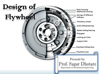
Design of Flywheel Rim
•
4 likes•1,150 views

1. The document discusses the design and operation of flywheels. Flywheels store energy during periods when energy production exceeds energy demand, and release energy during periods when demand exceeds production. 2. Flywheels are used in engines and machines to reduce fluctuations in speed by absorbing and releasing energy. They store energy from the power source during most of the operating cycle and provide energy during a short period. 3. Stresses in flywheel components include tensile stresses from centrifugal force and bending stresses from torque transmission. Flywheel design considers stresses, energy storage needs, and safety factors.

Recommended
More Related Content
What's hot
What's hot (20)
Similar to Design of Flywheel Rim
Similar to Design of Flywheel Rim (20)
More from Sagar Dhotare
More from Sagar Dhotare (20)
Recently uploaded
Recently uploaded (20)
Design of Flywheel Rim
- 2. Introduction Prof. Sagar A. Dhotare, Deparment of Mechanical Engineering, ViMEET. A flywheel used in machines serves as a reservoir which stores energy during the period when the supply of energy is more than the requirement and releases it during the period when the requirement of energy is more than supply. In case of steam engines, internal combustion engines, reciprocating compressors and pumps, the energy is developed during one stroke and the engine is to run for the whole cycle on the energy produced during this one stroke. For example, in I.C. engines, the energy is developed only during power stroke which is much more than the engine load, and no energy is being developed during suction, compression and exhaust strokes in case of four stroke engines and during compression in case of two stroke engines. The excess energy developed during power stroke is absorbed by the flywheel and releases it to the crankshaft during other strokes in which no energy is developed, thus rotating the crankshaft at a uniform speed. A little consideration will show that when the flywheel absorbs energy, its speed increases and when it releases, the speed decreases. Hence a flywheel does not maintain a constant speed, it simply reduces the fluctuation of speed. In machines where the operation is intermittent like punching machines, shearing machines, riveting machines, crushers etc., the flywheel stores energy from the power source during the greater portion of the operating cycle and gives it up during a small period of the cycle. Thus the energy from the power source to the machines is supplied practically at a constant rate throughout the operation.
- 3. Coefficient of Fluctuation of Speed Prof. Sagar A. Dhotare, Deparment of Mechanical Engineering, ViMEET.
- 4. Coefficient of Fluctuation of Speed Prof. Sagar A. Dhotare, Deparment of Mechanical Engineering, ViMEET. Permissible values for coefficient of fluctuation of speed (CS).
- 5. Fluctuation of Energy Prof. Sagar A. Dhotare, Deparment of Mechanical Engineering, ViMEET. The fluctuation of energy may be determined by the turning moment diagram for one complete cycle of operation. Consider a turning moment diagram for a single cylinder double acting steam engine as shown in Fig.1. The vertical ordinate represents the turning moment and the horizontal ordinate (abscissa) represents the crank angle. A little consideration will show that the turning moment is zero when the crank angle is zero. It rises to a maximum value when crank angle reaches 90º and it is again zero when crank angle is 180º. This is shown by the curve abc in Fig.1 and it represents the turning moment diagram for outstroke. The curve cde is the turning moment diagram for instroke and is somewhat similar to the curve abc. Fig1. Turning moment diagram for a single cylinder double acting steam engine. Since the work done is the product of the turning moment and the angle turned, therefore the area of the turning moment diagram represents the work done per revolution. In actual practice, the engine is assumed to work against the mean resisting torque, as shown by a horizontal line AF. The height of the ordinate aA represents the mean height of the turning moment diagram. Since it is assumed that the work done by the turning moment per revolution is equal to the work done against the mean resisting torque, therefore the area of the rectangle aA Fe is proportional to the work done against the mean resisting torque. We see in Fig.1, that the mean resisting torque line AF cuts the turning moment diagram at points B, C, D and E. When the crank moves from ‘a’ to ‘p’ the work done by the engine is equal to the area aBp, whereas the energy required is represented by the area aABp. In other words, the engine has done less work (equal to the area aAB) than the requirement.
- 6. Fluctuation of Energy Prof. Sagar A. Dhotare, Deparment of Mechanical Engineering, ViMEET. This amount of energy is taken from the flywheel and hence the speed of the flywheel decreases. Now the crank moves from p to q, the work done by the engine is equal to the area pBbCq, whereas the requirement of energy is represented by the area pBCq. Therefore the engine has done more work than the requirement. This excess work (equal to the area BbC) is stored in the flywheel and hence the speed of the flywheel increases while the crank moves from p to q. Similarly when the crank moves from q to r, more work is taken from the engine than is developed. This loss of work is represented by the area CcD. To supply this loss, the flywheel gives up some of its energy and thus the speed decreases while the crank moves from q to r. As the crank moves from r to s, excess energy is again developed given by the area DdE and the speed again increases. As the piston moves from s to e, again there is a loss of work and the speed decreases. The variations of energy above and below the mean resisting torque line are called fluctuation of energy. The areas BbC, CcD, DdE etc. represent fluctuations of energy. Fig. 2 Turning moment diagram for a four stroke internal combustion engine. A little consideration will show that the engine has a maximum speed either at q or at s. This is due to the fact that the flywheel absorbs energy while the crank moves from p to q and from r to s. On the other hand, the engine has a minimum speed either at p or at r. The reason is that the flywheel gives out some of its energy when the crank moves from a to p and from q to r. The difference between the maximum and the minimum energies is known as maximum fluctuation of energy.
- 7. Fluctuation of Energy Prof. Sagar A. Dhotare, Deparment of Mechanical Engineering, ViMEET. A turning moment diagram for a four stroke internal combustion engine is shown in Fig.2. We know that in a four stroke internal combustion engine, there is one working stroke after the crank has turned through 720º (or 4π radians). Since the pressure inside the engine cylinder is less than the atmospheric pressure during suction stroke, therefore a negative loop is formed as shown in Fig.2. During the compression stroke, the work is done on the gases, therefore a higher negative loop is obtained. In the working stroke, the fuel burns and the gases expand, therefore a large positive loop is formed. During exhaust stroke, the work is done on the gases, therefore a negative loop is obtained. A turning moment diagram for a compound steam engine having three cylinders and the resultant turning moment diagram is shown in Fig.3. The resultant turning moment diagram is the sum of the turning moment diagrams for the three cylinders. Fig. 3. Turning moment diagram for a compound steam engine. It may be noted that the first cylinder is the high pressure cylinder, second cylinder is the intermediate cylinder and the third cylinder is the low pressure cylinder. The cranks, in case of three cylinders are usually placed at 120º to each other.
- 8. Maximum Fluctuation of Energy Prof. Sagar A. Dhotare, Deparment of Mechanical Engineering, ViMEET. A turning moment diagram for a multi-cylinder engine is shown by a wavy curve in Fig.4. The horizontal line AG represents the mean torque line. Let a1, a3, a5 be the areas above the mean torque line and a2, a4 and a6 be the areas below the mean torque line. These areas represent some quantity of energy which is either added or subtracted from the energy of the moving parts of the engine. Fig.4. Turning moment diagram for a multi-cylinder engine. Let the energy in the flywheel at A = E, then from Fig.4, we have Energy at B = E + a1 Energy at C = E + a1 – a2 Energy at D = E + a1 – a2 + a3 Energy at E = E + a1 – a2 + a3 – a4 Energy at F = E + a1 – a2 + a3 – a4 + a5 Energy at G = E + a1 – a2 + a3 – a4 + a5 – a6 = Energy at A Let us now suppose that the maximum of these energies is at B and minimum at E. ∴ Maximum energy in the flywheel = E + a1 and minimum energy in the flywheel = E + a1 – a2 + a3 – a4 ∴ Maximum fluctuation of energy, ΔE = Maximum energy – Minimum energy = (E + a1) – (E + a1 – a2 + a3 – a4) = a2 – a3 + a4
- 9. Coefficient of Fluctuation of Energy Prof. Sagar A. Dhotare, Deparment of Mechanical Engineering, ViMEET.
- 10. Coefficient of Fluctuation of Energy Prof. Sagar A. Dhotare, Deparment of Mechanical Engineering, ViMEET. The following table shows the values of coefficient of fluctuation of energy for steam engines and internal combustion engines.
- 11. Energy Stored in a Flywheel Prof. Sagar A. Dhotare, Deparment of Mechanical Engineering, ViMEET. A flywheel is shown in Fig.5. We have already discussed that when a flywheel absorbs energy its speed increases and when it gives up energy its speed decreases. Fig. 5. Flywheel. m = Mass of the flywheel in kg, k = Radius of gyration of the flywheel in metres, I = Mass moment of inertia of the flywheel about the axis of rotation in kg-m2 = m.k2, N1 and N2 = Maximum and minimum speeds during the cycle in r.p.m., ω1 and ω2 = Maximum and minimum angular speeds during the cycle in rad / s,
- 12. Energy Stored in a Flywheel Prof. Sagar A. Dhotare, Deparment of Mechanical Engineering, ViMEET.
- 13. Energy Stored in a Flywheel Prof. Sagar A. Dhotare, Deparment of Mechanical Engineering, ViMEET. From this expression, we may find the value of the cross-sectional area of the rim. Assuming the cross-section of the rim to be rectangular, then A = b × t where b = Width of the rim, and t = Thickness of the rim. Knowing the ratio of b / t which is usually taken as 2, we may find the width and thickness of rim. 4. When the flywheel is to be used as a pulley, then the width of rim should be taken 20 to 40 mm greater than the width of belt.
- 14. Stresses in a Flywheel Rim Prof. Sagar A. Dhotare, Deparment of Mechanical Engineering, ViMEET. A flywheel, as shown in Fig.6 , consists of a rim at which the major portion of the mass or weight of flywheel is concentrated, a boss or hub for fixing the flywheel on to the shaft and a number of arms for supporting the rim on the hub. Fig. 6. Flywheel. The following types of stresses are induced in the rim of a flywheel: 1. Tensile stress due to centrifugal force, 2. Tensile bending stress caused by the restraint of the arms, and 3. The shrinkage stresses due to unequal rate of cooling of casting. These stresses may be very high but there is no easy method of determining. This stress is taken care of by a factor of safety. We shall now discuss the first two types of stresses as follows: 1. Tensile stress due to the centrifugal force :- The tensile stress in the rim due to the centrifugal force, assuming that the rim is unstrained by the arms, is determined in a similar way as a thin cylinder subjected to internal pressure. Let b = Width of rim, t = Thickness of rim, ρ = Density of flywheel material, ω = Angular speed of flywheel, v = Linear velocity of flywheel, and σt = Tensile or hoop stress. A = Cross-sectional area of rim = b × t, D = Mean diameter of flywheel R = Mean radius of flywheel,
- 15. Stresses in a Flywheel Rim Prof. Sagar A. Dhotare, Deparment of Mechanical Engineering, ViMEET. Consider a small element of the rim as shown shaded in Fig.7. Let it subtends an angle δθ at the centre of the flywheel. Volume of the small element = A.R.δθ ∴ Mass of the small element, dm = Volume × Density = A.R.δθ.ρ = ρ.A.R.δθ Fig. 7. Cross-section of a flywheel rim
- 16. Stresses in a Flywheel Rim Prof. Sagar A. Dhotare, Deparment of Mechanical Engineering, ViMEET. From the above expression, the mean diameter (D) of the flywheel may be obtained by using the relation, v = π D.N / 60 2. Tensile bending stress caused by restraint of the arms :- The tensile bending stress in the rim due to the restraint of the arms is based on the assumption that each portion of the rim between a pair of arms behaves like a beam fixed at both ends and uniformly loaded, as shown in Fig. 8, such that length between fixed ends, Fig. 8
- 17. Stresses in a Flywheel Rim Prof. Sagar A. Dhotare, Deparment of Mechanical Engineering, ViMEET.
- 18. Stresses in Flywheel Arms Prof. Sagar A. Dhotare, Deparment of Mechanical Engineering, ViMEET. The following stresses are induced in the arms of a flywheel. 1. Tensile stress due to centrifugal force acting on the rim. 2. Bending stress due to the torque transmitted from the rim to the shaft or from the shaft to the rim. 3. Shrinkage stresses due to unequal rate of cooling of casting. These stresses are difficult to determine. Fig. 9 1. Tensile stress due to the centrifugal force :- Due to the centrifugal force acting on the rim, the arms will be subjected to direct tensile stress whose magnitude is same as discussed in the previous article. ∴ Tensile stress in the arms,
- 19. Stresses in Flywheel Arms Prof. Sagar A. Dhotare, Deparment of Mechanical Engineering, ViMEET. 2. Bending stress due to the torque transmitted :- Due to the torque transmitted from the rim to the shaft or from the shaft to the rim, the arms will be subjected to bending, because they are required to carry the full torque load. In order to find out the maximum bending moment on the arms, it may be assumed as a cantilever beam fixed at the hub and carrying a concentrated load at the free end of the rim as shown in Fig. 9. T = Maximum torque transmitted by the shaft, R = Mean radius of the rim, r = Radius of the hub, n = Number of arms, and Z = Section modulus for the cross- section of arms.
- 20. Design of Flywheel Arms Prof. Sagar A. Dhotare, Deparment of Mechanical Engineering, ViMEET. The cross-section of the arms is usually elliptical with major axis as twice the minor axis, as shown in Fig.10, and it is designed for the maximum bending stress. Let a1 = Major axis, and b1 = Minor axis. Fig. 10. Elliptical cross section of arms. Assuming a1 = 2 b1, the dimensions of the arms may be obtained from equations (i) and (ii). Important Points: 1. The arms of the flywheel have a taper from the hub to the rim. The taper is about 20 mm per meter length of the arm for the major axis and 10 mm per meter length for the minor axis. 2. The number of arms are usually 6. Sometimes the arms may be 8, 10 or 12 for very large size flywheels. 3. The arms may be curved or straight. But straight arms are easy to cast and are lighter. 4. Since arms are subjected to reversal of stresses, therefore a minimum factor of safety 8 should be used. In some cases like punching machines and machines subjected to severe shock, a factor of safety 15 may be used. 5. The smaller flywheels (less than 600 mm diameter) are not provided with arms. They are made web type with holes in the web to facilitate handling
- 21. Design of Shaft, Hub and Key Prof. Sagar A. Dhotare, Deparment of Mechanical Engineering, ViMEET.
- 22. Construction of Flywheels Prof. Sagar A. Dhotare, Deparment of Mechanical Engineering, ViMEET. The flywheels of smaller size (upto 600 mm diameter) are casted in one piece. The rim and hub are joined together by means of web as shown in Fig. 22.19 (a). The holes in the web may be made for handling purposes. Fig. 11 Fig. 12. Split flywheel. In case the flywheel is of larger size (upto 2.5 meter diameter), the arms are made instead of web, as shown in Fig. 11 (b). The number of arms depends upon the size of flywheel and its speed of rotation. But the flywheels above 2.5 meter diameter are usually casted in two piece. Such a flywheel is known as split flywheel. A split flywheel has the advantage of relieving the shrinkage stresses in the arms due to unequal rate of cooling of casting. A flywheel made in two halves should be spilt at the arms rather than between the arms, in order to obtain better strength of the joint. The two halves of the flywheel are connected by means of bolts through the hub, as shown in Fig. 12. The two halves are also joined at the rim by means of cotter joint (as shown in Fig. 12) or shrink links (as shown in Fig. 13). The width or depth of the shrink link is taken as 1.25 to 1.35 times the thickness of link. The slot in the rim into which the link is inserted is made slightly larger than the size of link.
- 23. Construction of Flywheels Prof. Sagar A. Dhotare, Deparment of Mechanical Engineering, ViMEET. Fig. 13. Shrink links. The relative strength of a rim joint and the solid rim are given in the following table.
- 24. Numerical No. 1 Prof. Sagar A. Dhotare, Deparment of Mechanical Engineering, ViMEET. A punching press pierces 35 holes per minute in a plate using 10 kN-m of energy per hole during each revolution. Each piercing takes 40 per cent of the time needed to make one revolution. The punch receives power through a gear reduction unit which in turn is fed by a motor driven belt pulley 800 mm diameter and turning at 210 r.p.m. Find the power of the electric motor if overall efficiency of the transmission unit is 80 per cent. Design a cast iron flywheel to be used with the punching machine for a coefficient of steadiness of 5, if the space considerations limit the maximum diameter to 1.3 m. Allowable shear stress in the shaft material = 50 MPa Allowable tensile stress for cast iron = 4 MPa Density of cast iron = 7200 kg / m3 Given : No. of holes = 35 per min ; Energy per hole = 10 kN-m = 10 000 N-m ; d = 800 mm = 0.8 m ; N = 210 r.p.m. ; η = 80% = 0.8 ; 1/CS = 5 or CS = 1/5 = 0.2 ; Dmax = 1.3 m ; τ = 50 MPa = 50 N/mm2 ; σt = 4 MPa = 4 N/mm2 ; ρ = 7200 kg / m3
- 25. Numerical No. 1 Prof. Sagar A. Dhotare, Deparment of Mechanical Engineering, ViMEET.
- 26. Numerical No. 1 Prof. Sagar A. Dhotare, Deparment of Mechanical Engineering, ViMEET.
- 27. Numerical No. 1 Prof. Sagar A. Dhotare, Deparment of Mechanical Engineering, ViMEET.
- 28. Numerical No. 1 Prof. Sagar A. Dhotare, Deparment of Mechanical Engineering, ViMEET.
- 29. Numerical No. 1 Prof. Sagar A. Dhotare, Deparment of Mechanical Engineering, ViMEET.
- 30. Numerical No. 2 Prof. Sagar A. Dhotare, Deparment of Mechanical Engineering, ViMEET. Design and draw a cast iron flywheel used for a four stroke I.C engine developing 180 kW at 240 r.p.m. The hoop or centrifugal stress developed in the flywheel is 5.2 MPa, the total fluctuation of speed is to be limited to 3% of the mean speed. The work done during the power stroke is 1/3 more than the average work done during the whole cycle. The maximum torque on the shaft is twice the mean torque. The density of cast iron is 7220 kg/𝑚3 . Given: P = 180 kW = 180 × 103 W; N = 240 r.p.m. ; σt = 5.2 MPa = 5.2 × 10⁶ N/m2 ; N1 – N2 = 3% N ; ρ = 7220 kg/𝑚3 Fig. 14
- 31. Numerical No. 2 Prof. Sagar A. Dhotare, Deparment of Mechanical Engineering, ViMEET. First of all, let us find the maximum fluctuation of energy (ΔE). The turning moment diagram of a four stroke engine is shown in Fig. 14.
- 32. Numerical No. 2 Prof. Sagar A. Dhotare, Deparment of Mechanical Engineering, ViMEET.
- 33. Numerical No. 2 Prof. Sagar A. Dhotare, Deparment of Mechanical Engineering, ViMEET.
- 34. Numerical No. 2 Prof. Sagar A. Dhotare, Deparment of Mechanical Engineering, ViMEET.
- 35. Numerical No. 2 Prof. Sagar A. Dhotare, Deparment of Mechanical Engineering, ViMEET.
- 36. Numerical No. 2 Prof. Sagar A. Dhotare, Deparment of Mechanical Engineering, ViMEET.