Watt Governor

Hello Everyone! The best ppt on watt governor. Learners can easily grasp it if they go through the whole ppt. Also helpful for making projects on watt governor. By going through the ppt one can easily learn about the watt governor from basics. You can also apply the knowledge that you gained from this ppt in real life problems. About the ppt: Watt governor is the simplest and gravity controlled form of the centrifugal governors. It consists of two fly balls attached to the sleeve of negligible mass. The upper sides of arms are pivoted so that its balls can move upward and downward as they revolve with a vertical spindle. The engine drives the spindle through bevel gears. The lower arms are connected to the sleeves. The sleeve is keyed to the spindle in such a way that revolves with the spindle. At the same time, it can slide up and down according to the spindle speed. Two stoppers are provided at the bottom and top of the spindle to limit the movement sleeve. Watt governor is also known as simple conical governor. In the case of watts governor, the controlling force is provided by the action of gravity, at uniform speed controlling force is equal to the centrifugal force, and it balances each other. I will suggest to watch the whole ppt so that you can learn more about it. Thank You!

Recommended
More Related Content
What's hot
What's hot (20)
Similar to Watt Governor
Similar to Watt Governor (20)
More from Priyanshu
More from Priyanshu (11)
Recently uploaded
Recently uploaded (20)
Watt Governor
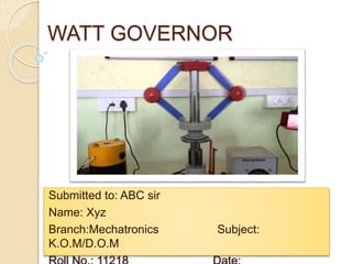
- 1. WATT GOVERNOR Submitted to: ABC sir Name: Xyz Branch:Mechatronics Subject: K.O.M/D.O.M
- 2. INTRODUCTION: A governor is a system that is used to maintain the mean speed of an engine, within certain limits, under fluctuating load conditions. It does this by regulating and controlling the amount of fuel supplied to the engine.
- 3. In general the speed of an engine varies in two ways-during each revolution(cyclic revolution) and over a number of revolutions. Watt governor is designed by James Watt in 1788 for his steam engine therefore it is called watt governor. Watt governor is the simplest form of centrifugal governors. Centrifugal governors are special type of governors with a feedback system that controls the speed of an engine by regulating the flow of fuel or working fluid.
- 6. Watt governor has two fly balls attached to two arms of negligible masses. Watt governor is used to supply the required amount of fuel at different speed. When the speed of engine increases, the supply of fuel needs to increase and as the engine speed decreases the supply of fuel should be decreased .
- 8. Watt governor consists of two fly balls which are located at the end of the arms . The upper parts of these two arms are pivoted to the spindle. This spindle is driven by the engine through the bevel gears. The lower parts of arms are connected to the sleeve which move upward or downward as the balls moves upward or downward .
- 9. Working: This is a short video about the working of watt governor (sir, please wait 2-3 sec. and click on the video to start with full screen mode and you have to be connected to the internet)
- 10. Watt governors consists of two balls which are attached to both arms which are of negligible mass. The upper side of arms are pivoted so that its balls can move upwards and downwards. These arms are connected to the spindle . The engine drives the spindle through bevel gears.
- 11. When the engine speed increases: When the speed of engine increases , the load on the engine decreases and the speed of rotation of spindle increases. The centrifugal force on balls increases and the balls move upwards and hence the sleeve moves upward.
- 12. The upward movement of sleeve causes the throttle valve at the end of the ball crank lever to decrease the fuel supply. The power output is reduced.
- 13. When the engine speed decreases: When the engine speed decreases, the load on engine increases and speed of rotation of spindle decrease. The centrifugal force on balls decreases and the balls moves downwards.
- 14. As the balls move downwards, hence the sleeve moves downward which causes the throttle valve to increase the fuel supply and the power output is increased.
- 15. Formula Used: Using reference of the above figure,
- 16. The spindle is driven by the output shaft of the prime mover. The balls are mounted at the junction of the two arms. The upper arms are connected to the spindle and lower arms are connected to the sleeve. The watt governor is suitable for low speed i.e. 60 to 80 rpm. The height of the governor. h=895/N2 where N=r.p.m
- 17. Let M=mass of the ball,kg W=weight of the ball,N h=height of the governor r=radial distance of the ball from the axis of the spindle w=angular velocity of the balls and arms about the spindle axis T=tension in the arm,N Now, Under equilibrium,
- 18. Take moment of the forces about O, For equilibrium,
- 20. The controlling force diagram shows you how the inward force varies with the radius of rotation and the effect of friction. Controlling force of governor is equal and opposite to the centrifugal action. Controlling force,fc=mw2r
- 21. Advantages: Watt governors are special type of governors with a feedback system that controls the speed of an engine by regulating the flow of fuel or working fluid. It can be operated at very high speed. It is smaller in size.
- 22. Disadvantages: Watt governors are limited to in vertical position applications. Watt governor is used in very slow speed engine. At higher speed, the sensitivity will decrease.
- 23. Applications: This mechanism is crucial to the industrial revolution – most of the textile, coal mining, tableware, steel mills and many other industries that were flourishing at the time required a stable engine speed from their steam engines to run effectively and efficiently.
- 24. Hydraulic control The flyweights are linked hydraulically to the fuel control assembly. This system consists of a pilot control valve which is connected to the governor spindle and a piston.
- 25. Governors are used in an Elevator. It acts as a stopping mechanism in case the elevator runs beyond its tripping speed (which is usually a factor of the maximum speed of the lift and is preset by the manufacturer as per the international lift safety guidelines).
- 26. For example, if you had a large factory that had many weaving machines that produced lengths of woven cotton to the tailors, with each machine powered by a series of belts by a steam engine, you would need all of your weaving machines to run at a constant speed, otherwise the material produced would have irregular weaves, be substandard and not sell-able.
- 27. Conclusio n Through this presentation we have learnt about the watt governor, it’s construction, working, formula used, force diagram, advantages, disadvantages and applications in various areas. Thank You For Any Queries: M.No.: xxxxxxxx22 E-Mail ID: …..@gmail.com