SlideShare a Scribd company logo
1 of 16
Download to read offline
Potential +/- Difference Inc.
ReGenX Generator Prototype No. 1
E Core Coil Design
Infinite Efficiency Performance Test Data for Design 1st
August 11th
, 2021
ReGenX Generator Prototype No. 1 E Core Coil Design
Prototype No. 1 employs a single conventional generator coil and a two ReGenX
Generator coils which are would on the same E Core.
The conventional generator coil is used to deliver electrical output power to the load
and establish conventional generator performance, i.e.:
1. on-load Generator Armature Reaction (Generator Magnetic Field induced
Counter-Electromagnetic-Torque/System Deceleration) and
2. to establish the conventional generator coil’s Load Current sine wave which
can be observed on an oscilloscope.
The ReGenX Generator coils are employed to establish ReGenX Generator
performance, i.e.:
3. to reverse the conventional generator’s on-load
Generator Armature Reaction/system deceleration,
4. to produce an on-load delayed Magnetic Field,
induced Complementary-Electromagnetic-Torque/System Acceleration,
5. to demonstrate Flux Harvesting,
6. to establish the ReGenX Generator Coils’
Load Current Delay which can be observed
simultaneously on the oscilloscope with the
conventional generator coil’s non-delayed
load current sine wave.
Prototype No. 1 employs an induction motor
prime mover, a tachometer and power analyzer
to monitor prime mover input power variations from the steady state, equilibrium no-load conditions.
Figure 1 Prototype No. 1.
No-Load Conventional Generator
All photo test data recorded in Table 1
FIGURE 2 No-Load, Steady State/Dynamic Equilibrium:
Prototype No. 1 is brought up to a no-load steady state speed of 3482 RPM. A rotational
equilibrium condition is established where the net drive shaft torque is zero and the mechanical
drive shaft input power to the generator is also zero.
On-Load Conventional Generator
FIGURE 3 Generator Output Power:
The conventional generator coil is placed on-load and delivers 11.4 Watts to the purely resistive
load.
FIGURE 4 On-Load, Reduced Steady State/Dynamic Equilibrium:
On-load Generator Armature Reaction decelerates the prime mover and the prime mover
induction motor responds by consuming additional stator current and power, additional torque
is delivered to the generators drive shaft by the prime mover.
11.4 Watts is delivered to the load by the conventional generator and 18 Watts is required by
the prime mover over the steady state no-load condition.
 Conventional Generator Electrical Output = 11.4 Watts
 Prime Mover Input Power Increase = + 18 Watts
 On-Load System Speed Reduction = - 23 Rpm
FIGURE 3
FIGURE 2
FIGURE 4
CONVENTIONAL GENERATOR Prototype No. 1 E Core Coil Design
Test Data Collection Date: March 20th
, 2018
Test Data Collector Name/Organization: Mark Hamilton Chief Engineer GAL Power Systems
Test Data Collection Location: Almonte ON
Table 1 Recorded and Calculated Test Data CONVENTIONAL GENERATOR:
Generator
Condition
Prime
Mover
INPUT
Voltage
(Volts)
Prime
Mover
INPUT
Current
(Amps)
Prime
Mover
INPUT
Power
Factor
Prime
Mover
INPUT
Power
(Watts)
System
Equilibrium
Speed
Drive Shaft NET
Torque = Zero
(RPM)
Conventiona
l Generator
OUTPUT
(Volts)
Conventional
Generator
OUTPUT
Current
(Amps)
Load
Power
Factor
Calculated
Conventional
Generator
OUTPUT
Load Power
(Watts)
Calculated
Prime Mover
On-Load
INPUT INCREASE
(Watts)
No-Load 111.6 1.51 0.93 156 3482 - - - - -
On-Load 111.5 1.68 0.93 174 3459 10.8 1.051 1 11.4 +18
Observation Notes: When the conventional generator coil is placed on-load from the steady state, no-load rotational equilibrium condition the
generator delivers electrical output power to the load and the generator decelerates the system due to Generator Armature Reaction and
additional input power is supplied by the prime mover.
Test Data Collector Signature/Date: ____________________________________________________________________________
No-Load ReGenX Generator
All photo test data recorded in Table 2
FIGURE 5:
Prototype No. 1 is brought up to a no-load steady state speed of 3482 RPM. A rotational
equilibrium condition is established where the net drive shaft torque is zero and the
mechanical drive shaft input power to the generator is also zero.
On-Load ReGenX Generator Coil #1
FIGURE 6:
The ReGenX Generator coil # 1 is placed on-load 13.0 Watts to the purely resistive load.
FIGURE 7:
On-load ReGenX Generator accelerates the prime mover and the prime mover induction motor
responds by consuming a reduction in stator current and a reduction in power and reduced
torque is delivered to the generators drive shaft by the prime mover.
13.3 Watts is delivered to the load by the ReGenX Generator coil #1 and a 4 Watt reduction is
realized by the prime mover over the no-load steady state condition.
 ReGenX Generator Coil #1 Electrical Output = 13.0 Watts
 Prime Mover Input Power Reduction = - 4 Watts
 On-Load System Speed Increase = + 8 RPM
FIGURE 5
FIGURE 6
FIGURE 7
On-Load ReGenX Generator Coil #1 & Coil #2
FIGURE 8:
The ReGenX Generator coil # 2 is also placed on-load and delivers a total of 13.2 Watts to the
purely resistive load.
FIGURE 9:
On-load ReGenX Generator Armature Reaction accelerates the prime mover and the prime
mover induction motor responds by consuming a reduction in stator current and power, a
reduction in torque is delivered to the generators drive shaft by the prime mover.
13.2 Watts is delivered to the load by the ReGenX Generaor coil #1 and Coil #2 and an 8 Watt
reduction is realized by the prime mover over the steady state no-load condition.
 ReGenX Generator Coil #1 Electrical OUTPUT = 13.2 Watts
 Prime Mover Input Power Reduction = - 8 Watts
 System Speed Increase = +13 RPM
ReGenX Generator Flux Harvesting
The discharging Delayed Magnetic Flux from the ReGenX Generator coils serves several
functions:
1. it accelerates the on-load generator’s permanent magnet rotor (rotating magnetic field),
2. which accelerates the prime mover,
3. which reduces the prime mover’s on-load current and power consumption,
4. the discharging magnetic flux is collected in the conventional generator coil’s core,
5. which increases the core’s net flux change, thus increasing the induced voltage, current and power delivered across the load.
FIGURE 8
FIGURE 9
ReGenX Generator Prototype No. 1 E Core Coil Design
Table 2 Recorded Data ReGenX GENERATOR Coil #1 & Coil #2:
Generator
Condition
Prime
Mover
INPUT
Voltage
(Volts)
Prime
Mover
INPUT
Current
(Amps)
Prime
Mover
INPUT
Power
Factor
Prime
Mover
INPUT
Power
(Watts)
System
Equilibrium
Speed
Drive Shaft NET
Torque = Zero
(RPM)
ReGenX
Generator
OUTPUT
(Volts)
ReGenX
Generator
OUTPUT
Current
(Amps)
Load
Power
Factor
Calculated
ReGenX
Generator
OUTPUT
Load Power
(Watts)
Calculated
Prime Mover
On-Load
INPUT
DECREASE
(Watts)
No-Load 111.6 1.51 0.93 156 3482 - - - - -
Coil #1
On-Load 112.1 1.49 0.91 149 3490 11.8 1.10 1 13.0 -4
Coil #2
On-Load 112.3 1.48 0.91 148 3495 11.9 1.11 1 13.2 -13
Observation Notes: When the ReGenX Generator coils are placed on-load from the steady state, no-load rotational equilibrium condition the
conventional generator coil delivers power to the load, the ReGenX Generator coils accelerate the system due to Generator Armature Reaction
reversal and a reduction in input power is realized by the prime mover. The more power delivered to the load in ReGenX Generator Mode, the
more the system is accelerated and the more the prime mover input power consumption is reduced. Discharging magnetic flux by the ReGenX
Generator coil accelerates the system and increases the voltage, current and power delivered to the load by the conventional generator coil due
to Flux Harvesting.
Test Data Collector Signature/Date: ____________________________________________________________________________
Load Current Sine Waves
On-Load Load Current Sine Waves
Conventional Generator Coil and ReGenX Generator Coils
FIGURE 10:
The load current sine wave for the conventional coil (Green) is
displayed on the oscilloscope and the Delayed Load Current for the
ReGenX Generator coil #1(Purple) is also shown.
Figure 11:
The load current sine wave for the conventional coil (Green) is
displayed on the oscilloscope and the Delayed Load Current for the
ReGenX Generator coil #1 and coil #2 (Purple) is also shown.
FIGURE 10
FIGURE 11
ReGenX Generator Prototype No. 1 E Core Coil Design
Table 3 Recorded Data ReGenX GENERATOR Load Current Sine Wave Delay:
Generator Condition ReGenX Generator
Coil 1
Load Current Delay
(Degrees)
ReGenX Generator
Coil 2
Load Current Delay
(Degrees)
On-Load 47 degrees 108 degrees
Test Data Collector Signature/Date: ____________________________________________________________________________
Data Summary Conventional Generator Coil and ReGenX Generator Coils
Table 1 & 2 Recorded and Calculated Data Summary CONVENTIONAL GENERATOR Coil and ReGenX GENERATOR Coil #1 & Coil #2:
“Black Box” Efficiency Data Calculations Mechanical to Electrical Conversion Efficiencies
Generator
Type
and
Generator
Condition
Prime
Mover
INPUT
Voltage
(Volts)
Prime
Mover
INPUT
Current
(Amps)
Prime
Mover
INPUT
Power
Factor
Prime
Mover
INPUT
Power
(Watts)
System
Equilibrium
Speed
Drive Shaft NET
Torque = Zero
(RPM)
On-Load
System
Speed
Response
Decrease/
Increase
(RPM)
Generator
OUTPUT
(Volts)
Generator
OUTPUT
Current
(Amps)
Load
Power
Factor
Calculated
Generator
OUTPUT
Load
Power
(Watts)
Calculated
Prime Mover
On-Load
Response
INPUT
Increase/
Decrease
(Watts)
No-Load 111.6 1.51 0.93 156 3482 - - - - - -
Conventiona
l Generator
On-Load
111.5 1.68 0.93 174 3459 Decrease
-23
10.8 1.051 1 11.4 +18
ReGenX
Generator
Coil #1
On-Load
112.1 1.49 0.91 149 3490 Increase
+31
11.8 1.10 1 13.0 -4
Coil #2
On-Load 112.3 1.48 0.91 148 3495 Increase
+36
11.9 1.11 1 13.2 -13
Introduction:
An electric generator is a machine that converts mechanical drive shaft input power to electrical output power.
At any operational No-Load, Steady State Speed or Rotational Equilibrium condition the drive shaft’s Mechanical Input Power (Pin) to the
generator is always 0.00 Watts because;
Mechanical Drive Shaft Input Power (P) = Net Torque(T) x System Rotational Speed(ω):
Pin = T x ω
Because T(net) = 0.00 at Rotational Equilibrium
Mechanical Drive Shaft Input Power (Pin) on No-Load always equals
0.00 Watts
When the generator is placed on load the drive shaft’s mechanical
input power is provided by the prime mover, which must always be
increased (due to Generator Armature Reaction) in order to deliver
power to the load or the system will stall.
For example;
If the generator delivered 9 Watts to the load and the prime mover
input increased by 10 Watts the “Black Box” System Efficiency would
be:
Generator Conversion Efficiency = Output/Input x 100
or
9/10 x 100 = 90% Black Box Conversion Efficiency
What is Rotational Equilibrium?
The concept of rotational equilibrium is an equivalent to
Newton’s 1ˢᵗ law for a rotational system.
An object which is not rotating remains not rotating unless acted
on by an external torque. Similarly, an object rotating at
constant angular velocity remains rotating unless acted on by an
external torque.
In this case it is the net torque which is important.
If the net torque on a rotatable object is zero then it will be in
rotational equilibrium and not able to acquire angular
acceleration.
https://www.khanacademy.org/science/physics/torque-angular-
momentum/torque-tutorial/a/torque
“Black Box” Efficiency Data Calculations Mechanical to Electrical Conversion Efficiencies
If the generator delivered 5 Watts to the load and the prime mover input increased by 10 Watts the Black Box System Efficiency would be:
5/10 x 100 = 50% Conversion Efficiency
If the generator delivered 10 Watts to the load and the prime mover input increased by 10 Watts the Black Box System Efficiency would
be:
10/10 x 100 = 100% Conversion Efficiency
If the generator delivered 10 Watts to the load and the prime mover input increased by 0 Watts (in other words did not increase at all or
was reduced to below the no-load idle input condition of 0 Watts), the Black Box System Efficiency would be:
10/0 x 100 = Infinite % Conversion Efficiency
Actual Generator Conversion Efficiency
The Actual Generator Conversion Efficiency would be the Prime Mover Input Increase (Watts) x Prime Mover (induction motor) Electrical
to Mechanical Conversion Efficiency (%) which would be about 85% for the induction motor prime movers used and the speed of
operation.
All of the tests in this document are operated at identical, torques and speeds and from an initial operating no-load, Rotational
Equilibrium condition where the mechanical input power is always 0.00 Watts
Black Box System Efficiency Calculations ReGenX GENERATOR
Table 9 Calculated Data Black Box System Efficiency ReGenX Generator
Device Type Drive Shaft
Net Torque
at Equilibrium
(Nm)
Calculated
Drive Shaft
INPUT POWER
No-Load/
Equilibrium
P = Tnet x Speed
(Watts)
INPUT
Calculated
On-Load
Prime Mover
Decrease
(Watts)
Drive Shaft
Torque Decrease
(Nm)
OUTPUT
Calculated
Load Power
(Watts)
BLACK BOX
EFFICIENCY
Calculated
System Efficiency
Output/Input x 100
(%)
ReGenX
Generator Coil #1
Prototype #1
0.00 0.00 -3 - 0.008 12.9 ∞
ReGenX
Generator Coil #2
Prototype #1
0.00 0.00 -7 -0.02 13.2 ∞
Torque = KW x 9550/RPM
Black Box System Efficiency Calculations CONVENTIONAL GENERATOR and ReGenX GENERATOR
Table 10 Calculated Data Black Box System Efficiency CONVENTIONAL GENERATOR and ReGenX GENERATOR
Device Type Drive Shaft
Net Torque
at
Equilibrium
(Nm)
Calculated
Drive Shaft
INPUT POWER
No-Load/
Equilibrium
P = Tnet x Speed
(Watts)
INPUT
Calculated
On-Load
Prime Mover
Increase/Decrease
(Watts)
Drive Shaft
Torque
Increase/Decrease
(Nm)
OUTPUT
Calculated
Load Power
(Watts)
BLACK BOX
Calculated
System
EFFICIENCY
Output/Input x
100
(%)
Conventional
Generator Coil
Prototype #1
0.00 0.00 +20 + 0.06 11.1 > 55.5%
ReGenX
Generator Coil
#1
Prototype #1
0.00 0.00 -3 -0.008 12.9 ∞
ReGenX
Generator Coil
#2
Prototype #1
0.00 0.00 -7 -0.02 13.2 ∞
Test Data Calculator Signature/Date: ____________________________________________________________________________
Data and Efficiency Summaries ReGenX GENERATOR
Table 12 Calculated Data Black Box System Efficiency Conventional Generator, and ReGenX Generator,
Device Type Drive Shaft
Net Torque
at Equilibrium
(Nm)
Calculated
Mechanical
Drive Shaft
INPUT POWER
No-Load /
Equilibrium
P = Tnet x Speed
(Watts)
INPUT
Calculated
Prime Mover
On-Load Increase
(Watts)
Drive Shaft
Torque
Increase/Decrease
(Nm)
OUTPUT
Calculated Load
Power
(Watts)
Black Box
Calculated System
EFFICIENCY
Output/Input x 100
(%)
Conventional
Generator Coil
Prototype #1
0.00 0.00 +20 + 0.06 11.1 > 55.5%
ReGenX
Generator Coil #1
Prototype #1 0.00 0.00 -3 -0.008 12.9 ∞
ReGenX
Generator Coil #2
Prototype #1 0.00 0.00 -7 -0.02 13.2 ∞
Conclusions
Performance data for a conventional generator and conventional generator/transformer were presented. All Conventional generators and
transformers operate at below 100% efficiency in their conversions of mechanical drive shaft input power to electrical output power.
Performance data for a ReGenX Generator, Bi-Toroid Transformer and an EV Regenerative Acceleration (ReGenX) Generator were also
presented. The ReGenX Generator, Bi-Toroid Transformer and EV Regenerative Acceleration (ReGenX) Generator all operate with a Load
Current Delay which allows them to require a 0.00 Watt prime mover input increase (infinite efficiency) when placed on-load and when
delivering power to the load.
Conventional Generator Armature Reaction, Counter-Electromagnetic-Torque/system deceleration has now been replaced with ReGenX
Generator Delayed Armature Reaction, Complementary-Electromagnetic-Torque/system acceleration.
Electric Power Generation Applications
The ReGenX Generator and Bi-Toroid innovation technologies now allow for electric power generation with less mechanical input power to be
supplied to the generator on-load than is required at idle on no-load. This translates to more than a 80% reduction in input costs and 80% less
output pollution and more than an 80% cost of purchasing electricity to the consumer.
Electric Vehicle Applications
The Electric Vehicle (EV) Regenerative Acceleration (ReGenX) Generator now allows electric vehicle generators to recharge the EV’s batteries
while simultaneously accelerating the EV above a certain speed and also to recharge the EV’s batteries while simultaneously decelerating the EV
below a certain speed.
The greater the magnitude of battery recharging in EV Regenerative Acceleration Mode the faster the rate of battery recharging and the faster
the rate of EV acceleration. The greater the magnitude of battery recharging in EV regenerative braking mode the faster the rate of battery
recharging and the faster the rate of EV deceleration.
The magnitude of battery recharging current supplied by the ReGenX Generator in EV Regenerative Acceleration Mode is limited only by the
physical size of the ReGen-X Motor used.

More Related Content

Similar to Design 1st ReGenX Generator E Core Prototype #1 Performance Test Data.pdf

Advanced Energy ReGenX Generator and ReGen-X Quantum Motor and the LAW OF CRE...
Advanced Energy ReGenX Generator and ReGen-X Quantum Motor and the LAW OF CRE...Advanced Energy ReGenX Generator and ReGen-X Quantum Motor and the LAW OF CRE...
Advanced Energy ReGenX Generator and ReGen-X Quantum Motor and the LAW OF CRE...
Thane Heins
 
Ottawa University / NRC ReGenX Test Set-up
Ottawa University / NRC ReGenX Test Set-upOttawa University / NRC ReGenX Test Set-up
Ottawa University / NRC ReGenX Test Set-up
Thane Heins
 
FINAL Potential Difference inc. Innovations Test Program with 13 Internationa...
FINAL Potential Difference inc. Innovations Test Program with 13 Internationa...FINAL Potential Difference inc. Innovations Test Program with 13 Internationa...
FINAL Potential Difference inc. Innovations Test Program with 13 Internationa...
Thane Heins
 
Discussion Document RE: Complete Potential Difference Innovations Test Program
Discussion Document RE: Complete Potential Difference Innovations Test ProgramDiscussion Document RE: Complete Potential Difference Innovations Test Program
Discussion Document RE: Complete Potential Difference Innovations Test Program
Thane Heins
 
Potential Difference National Research Council of Canada Report Final
Potential Difference National Research Council of Canada Report FinalPotential Difference National Research Council of Canada Report Final
Potential Difference National Research Council of Canada Report Final
Thane Heins
 
Intelectual Property Presentation - ReGen-X Concentric 8 Multi-Function Tricoil
Intelectual Property Presentation - ReGen-X Concentric 8 Multi-Function TricoilIntelectual Property Presentation - ReGen-X Concentric 8 Multi-Function Tricoil
Intelectual Property Presentation - ReGen-X Concentric 8 Multi-Function Tricoil
Thane Heins
 

Similar to Design 1st ReGenX Generator E Core Prototype #1 Performance Test Data.pdf (20)

HILLCREST PETROLEUM AND DESIGN 1ST ReGenX GENERATOR & MOTOR Prototypes 1, 2, ...
HILLCREST PETROLEUM AND DESIGN 1ST ReGenX GENERATOR & MOTOR Prototypes 1, 2, ...HILLCREST PETROLEUM AND DESIGN 1ST ReGenX GENERATOR & MOTOR Prototypes 1, 2, ...
HILLCREST PETROLEUM AND DESIGN 1ST ReGenX GENERATOR & MOTOR Prototypes 1, 2, ...
 
ReGenX Generator Prototypes for Advanced Energy Performance Testing and Valid...
ReGenX Generator Prototypes for Advanced Energy Performance Testing and Valid...ReGenX Generator Prototypes for Advanced Energy Performance Testing and Valid...
ReGenX Generator Prototypes for Advanced Energy Performance Testing and Valid...
 
Advanced Energy ReGenX Generator and ReGen-X Quantum Motor and the LAW OF CRE...
Advanced Energy ReGenX Generator and ReGen-X Quantum Motor and the LAW OF CRE...Advanced Energy ReGenX Generator and ReGen-X Quantum Motor and the LAW OF CRE...
Advanced Energy ReGenX Generator and ReGen-X Quantum Motor and the LAW OF CRE...
 
ReGenX Generator and ReGenX Quantum Motor Test and Performance Protocol
ReGenX Generator and ReGenX Quantum Motor Test and Performance ProtocolReGenX Generator and ReGenX Quantum Motor Test and Performance Protocol
ReGenX Generator and ReGenX Quantum Motor Test and Performance Protocol
 
HRH Hillcrest Petroleum and Design 1st Infinite Efficiency ReGenX Generator a...
HRH Hillcrest Petroleum and Design 1st Infinite Efficiency ReGenX Generator a...HRH Hillcrest Petroleum and Design 1st Infinite Efficiency ReGenX Generator a...
HRH Hillcrest Petroleum and Design 1st Infinite Efficiency ReGenX Generator a...
 
Ottawa University / NRC ReGenX Test Set-up
Ottawa University / NRC ReGenX Test Set-upOttawa University / NRC ReGenX Test Set-up
Ottawa University / NRC ReGenX Test Set-up
 
#6 DATA FINAL Potential Difference Innovations Test Program WITH INTERNATIONA...
#6 DATA FINAL Potential Difference Innovations Test Program WITH INTERNATIONA...#6 DATA FINAL Potential Difference Innovations Test Program WITH INTERNATIONA...
#6 DATA FINAL Potential Difference Innovations Test Program WITH INTERNATIONA...
 
FINAL Potential Difference inc. Innovations Test Program with 13 Internationa...
FINAL Potential Difference inc. Innovations Test Program with 13 Internationa...FINAL Potential Difference inc. Innovations Test Program with 13 Internationa...
FINAL Potential Difference inc. Innovations Test Program with 13 Internationa...
 
Discussion Document RE: Complete Potential Difference Innovations Test Program
Discussion Document RE: Complete Potential Difference Innovations Test ProgramDiscussion Document RE: Complete Potential Difference Innovations Test Program
Discussion Document RE: Complete Potential Difference Innovations Test Program
 
Infinite Efficiency HILLCREST PETROLEUM AND DESIGN 1ST Potential Difference I...
Infinite Efficiency HILLCREST PETROLEUM AND DESIGN 1ST Potential Difference I...Infinite Efficiency HILLCREST PETROLEUM AND DESIGN 1ST Potential Difference I...
Infinite Efficiency HILLCREST PETROLEUM AND DESIGN 1ST Potential Difference I...
 
Hillcrest Petroleum & Design 1st ReGenX Performance Testing Plan 2021-00-21
Hillcrest Petroleum & Design 1st ReGenX Performance Testing Plan 2021-00-21Hillcrest Petroleum & Design 1st ReGenX Performance Testing Plan 2021-00-21
Hillcrest Petroleum & Design 1st ReGenX Performance Testing Plan 2021-00-21
 
Potential Difference inc. Innovations RE: Design 1st Performance Testing Plan...
Potential Difference inc. Innovations RE: Design 1st Performance Testing Plan...Potential Difference inc. Innovations RE: Design 1st Performance Testing Plan...
Potential Difference inc. Innovations RE: Design 1st Performance Testing Plan...
 
Potential Difference National Research Council of Canada Report Final
Potential Difference National Research Council of Canada Report FinalPotential Difference National Research Council of Canada Report Final
Potential Difference National Research Council of Canada Report Final
 
POTENTIAL DIFFERENCE - NRC Reportkc.pdf
POTENTIAL DIFFERENCE - NRC Reportkc.pdfPOTENTIAL DIFFERENCE - NRC Reportkc.pdf
POTENTIAL DIFFERENCE - NRC Reportkc.pdf
 
#72 Smart and Biggar Intelectual Property Presentation RE ReGen-X Concentric ...
#72 Smart and Biggar Intelectual Property Presentation RE ReGen-X Concentric ...#72 Smart and Biggar Intelectual Property Presentation RE ReGen-X Concentric ...
#72 Smart and Biggar Intelectual Property Presentation RE ReGen-X Concentric ...
 
ReGenX Concentric 8 Multi-function Tricoil Intelectual Property Presentation
ReGenX Concentric 8 Multi-function Tricoil Intelectual Property PresentationReGenX Concentric 8 Multi-function Tricoil Intelectual Property Presentation
ReGenX Concentric 8 Multi-function Tricoil Intelectual Property Presentation
 
Intelectual Property Presentation - ReGen-X Concentric 8 Multi-Function Trico...
Intelectual Property Presentation - ReGen-X Concentric 8 Multi-Function Trico...Intelectual Property Presentation - ReGen-X Concentric 8 Multi-Function Trico...
Intelectual Property Presentation - ReGen-X Concentric 8 Multi-Function Trico...
 
Intelectual Property Presentation - ReGen-X Concentric 8 Multi-Function Tricoil
Intelectual Property Presentation - ReGen-X Concentric 8 Multi-Function TricoilIntelectual Property Presentation - ReGen-X Concentric 8 Multi-Function Tricoil
Intelectual Property Presentation - ReGen-X Concentric 8 Multi-Function Tricoil
 
EVS 29 EV Regenerative Acceleration (ReGenX) Generator Demonstration Performa...
EVS 29 EV Regenerative Acceleration (ReGenX) Generator Demonstration Performa...EVS 29 EV Regenerative Acceleration (ReGenX) Generator Demonstration Performa...
EVS 29 EV Regenerative Acceleration (ReGenX) Generator Demonstration Performa...
 
Draft ReGenX Generator Innovation Technology and Commercialization Readiness ...
Draft ReGenX Generator Innovation Technology and Commercialization Readiness ...Draft ReGenX Generator Innovation Technology and Commercialization Readiness ...
Draft ReGenX Generator Innovation Technology and Commercialization Readiness ...
 

More from Thane Heins

THE HISTORY OF OERSTED'S LAW OF CREATION OF ENERGY 1820-2024.pdf
THE HISTORY OF OERSTED'S LAW OF CREATION OF ENERGY 1820-2024.pdfTHE HISTORY OF OERSTED'S LAW OF CREATION OF ENERGY 1820-2024.pdf
THE HISTORY OF OERSTED'S LAW OF CREATION OF ENERGY 1820-2024.pdf
Thane Heins
 
AI Published & MIT Validated Perpetual Motion Machine Breakthroughs (2 New EV...
AI Published & MIT Validated Perpetual Motion Machine Breakthroughs (2 New EV...AI Published & MIT Validated Perpetual Motion Machine Breakthroughs (2 New EV...
AI Published & MIT Validated Perpetual Motion Machine Breakthroughs (2 New EV...
Thane Heins
 
UNIVERSITY OF OTTAWA 16th ANNIVERSARY PERPETUAL MOTION MACHINE RESEARCH AND D...
UNIVERSITY OF OTTAWA 16th ANNIVERSARY PERPETUAL MOTION MACHINE RESEARCH AND D...UNIVERSITY OF OTTAWA 16th ANNIVERSARY PERPETUAL MOTION MACHINE RESEARCH AND D...
UNIVERSITY OF OTTAWA 16th ANNIVERSARY PERPETUAL MOTION MACHINE RESEARCH AND D...
Thane Heins
 

More from Thane Heins (20)

THE HISTORY OF OERSTED'S LAW OF CREATION OF ENERGY 1820-2024.pdf
THE HISTORY OF OERSTED'S LAW OF CREATION OF ENERGY 1820-2024.pdfTHE HISTORY OF OERSTED'S LAW OF CREATION OF ENERGY 1820-2024.pdf
THE HISTORY OF OERSTED'S LAW OF CREATION OF ENERGY 1820-2024.pdf
 
World Electric Vehicle Journal RE Elon Musk, Tesla BYD & NIO Re-Introduction ...
World Electric Vehicle Journal RE Elon Musk, Tesla BYD & NIO Re-Introduction ...World Electric Vehicle Journal RE Elon Musk, Tesla BYD & NIO Re-Introduction ...
World Electric Vehicle Journal RE Elon Musk, Tesla BYD & NIO Re-Introduction ...
 
AI Published & MIT Validated Perpetual Motion Machine Breakthroughs (2 New EV...
AI Published & MIT Validated Perpetual Motion Machine Breakthroughs (2 New EV...AI Published & MIT Validated Perpetual Motion Machine Breakthroughs (2 New EV...
AI Published & MIT Validated Perpetual Motion Machine Breakthroughs (2 New EV...
 
AI Published & MIT Validated Perpetual Motion Machine Breakthroughs (2 New EV...
AI Published & MIT Validated Perpetual Motion Machine Breakthroughs (2 New EV...AI Published & MIT Validated Perpetual Motion Machine Breakthroughs (2 New EV...
AI Published & MIT Validated Perpetual Motion Machine Breakthroughs (2 New EV...
 
UNIVERSITY OF OTTAWA 16th ANNIVERSARY PERPETUAL MOTION MACHINE RESEARCH AND D...
UNIVERSITY OF OTTAWA 16th ANNIVERSARY PERPETUAL MOTION MACHINE RESEARCH AND D...UNIVERSITY OF OTTAWA 16th ANNIVERSARY PERPETUAL MOTION MACHINE RESEARCH AND D...
UNIVERSITY OF OTTAWA 16th ANNIVERSARY PERPETUAL MOTION MACHINE RESEARCH AND D...
 
UNIVERSITY OF OTTAWA 16th ANNIVERSARY LAW OF CREATION OF ENERGY & NEW FIRST L...
UNIVERSITY OF OTTAWA 16th ANNIVERSARY LAW OF CREATION OF ENERGY & NEW FIRST L...UNIVERSITY OF OTTAWA 16th ANNIVERSARY LAW OF CREATION OF ENERGY & NEW FIRST L...
UNIVERSITY OF OTTAWA 16th ANNIVERSARY LAW OF CREATION OF ENERGY & NEW FIRST L...
 
Potential Difference inc. Patent Portfolio.pdf
Potential Difference inc. Patent Portfolio.pdfPotential Difference inc. Patent Portfolio.pdf
Potential Difference inc. Patent Portfolio.pdf
 
Ukrainian Institute of Thermophysics Purchase order Agreement.pdf
Ukrainian Institute of Thermophysics Purchase order Agreement.pdfUkrainian Institute of Thermophysics Purchase order Agreement.pdf
Ukrainian Institute of Thermophysics Purchase order Agreement.pdf
 
UKRAINIAN Kyiv Institute of Thermophysics Memorandum_English.pdf
UKRAINIAN Kyiv Institute of Thermophysics Memorandum_English.pdfUKRAINIAN Kyiv Institute of Thermophysics Memorandum_English.pdf
UKRAINIAN Kyiv Institute of Thermophysics Memorandum_English.pdf
 
FINAL Shehnaz and Thane Interview PowerPoint ;-).pdf
FINAL Shehnaz and Thane Interview PowerPoint ;-).pdfFINAL Shehnaz and Thane Interview PowerPoint ;-).pdf
FINAL Shehnaz and Thane Interview PowerPoint ;-).pdf
 
UNIVERSITY OF OTTAWA 16th ANNIVERSARY PERPETUAL MOTION MACHINE RESEARCH AND D...
UNIVERSITY OF OTTAWA 16th ANNIVERSARY PERPETUAL MOTION MACHINE RESEARCH AND D...UNIVERSITY OF OTTAWA 16th ANNIVERSARY PERPETUAL MOTION MACHINE RESEARCH AND D...
UNIVERSITY OF OTTAWA 16th ANNIVERSARY PERPETUAL MOTION MACHINE RESEARCH AND D...
 
DRAFT - PIERRE POILIEVERE and NRC MITCH DAVIES 2024 HOUSE OF COMMONS INTRODUC...
DRAFT - PIERRE POILIEVERE and NRC MITCH DAVIES 2024 HOUSE OF COMMONS INTRODUC...DRAFT - PIERRE POILIEVERE and NRC MITCH DAVIES 2024 HOUSE OF COMMONS INTRODUC...
DRAFT - PIERRE POILIEVERE and NRC MITCH DAVIES 2024 HOUSE OF COMMONS INTRODUC...
 
#1 (zzzzz) 4 of 7 PHILIPS - A BiTT of explanation_flux_details 1.pdf
#1 (zzzzz) 4 of 7 PHILIPS - A BiTT of explanation_flux_details 1.pdf#1 (zzzzz) 4 of 7 PHILIPS - A BiTT of explanation_flux_details 1.pdf
#1 (zzzzz) 4 of 7 PHILIPS - A BiTT of explanation_flux_details 1.pdf
 
#1 (zzzzz) 3 of 7 PHILIPS BiTT basic principle_V4.pdf
#1 (zzzzz) 3 of 7 PHILIPS BiTT basic principle_V4.pdf#1 (zzzzz) 3 of 7 PHILIPS BiTT basic principle_V4.pdf
#1 (zzzzz) 3 of 7 PHILIPS BiTT basic principle_V4.pdf
 
#1 (zzzz) Bi-Toroid Transformer Patent.pdf
#1 (zzzz) Bi-Toroid Transformer Patent.pdf#1 (zzzz) Bi-Toroid Transformer Patent.pdf
#1 (zzzz) Bi-Toroid Transformer Patent.pdf
 
#1 (zzz) Patents by Inventor Thane C.pdf
#1 (zzz) Patents by Inventor Thane C.pdf#1 (zzz) Patents by Inventor Thane C.pdf
#1 (zzz) Patents by Inventor Thane C.pdf
 
US AIR FORCE, NASA, RUSSIAN ACADEMY OF SCIENCE LETTERS.pdf
US AIR FORCE, NASA, RUSSIAN ACADEMY OF SCIENCE LETTERS.pdfUS AIR FORCE, NASA, RUSSIAN ACADEMY OF SCIENCE LETTERS.pdf
US AIR FORCE, NASA, RUSSIAN ACADEMY OF SCIENCE LETTERS.pdf
 
TYPES OF WORK PERFORMED IN FARADAY'S ELECTRIC GENERATOR EXPERIMENT OF 1834.pdf
TYPES OF WORK PERFORMED IN FARADAY'S ELECTRIC GENERATOR EXPERIMENT OF 1834.pdfTYPES OF WORK PERFORMED IN FARADAY'S ELECTRIC GENERATOR EXPERIMENT OF 1834.pdf
TYPES OF WORK PERFORMED IN FARADAY'S ELECTRIC GENERATOR EXPERIMENT OF 1834.pdf
 
The Nature of Sub-Atomic Quantum Photon Energy Creation around a Current Carr...
The Nature of Sub-Atomic Quantum Photon Energy Creation around a Current Carr...The Nature of Sub-Atomic Quantum Photon Energy Creation around a Current Carr...
The Nature of Sub-Atomic Quantum Photon Energy Creation around a Current Carr...
 
The Law of Creation of Energy 2.pdf
The Law of Creation of Energy 2.pdfThe Law of Creation of Energy 2.pdf
The Law of Creation of Energy 2.pdf
 

Recently uploaded

Maher Othman Interior Design Portfolio..
Maher Othman Interior Design Portfolio..Maher Othman Interior Design Portfolio..
Maher Othman Interior Design Portfolio..
MaherOthman7
 
electrical installation and maintenance.
electrical installation and maintenance.electrical installation and maintenance.
electrical installation and maintenance.
benjamincojr
 
Artificial intelligence presentation2-171219131633.pdf
Artificial intelligence presentation2-171219131633.pdfArtificial intelligence presentation2-171219131633.pdf
Artificial intelligence presentation2-171219131633.pdf
Kira Dess
 
Tembisa Central Terminating Pills +27838792658 PHOMOLONG Top Abortion Pills F...
Tembisa Central Terminating Pills +27838792658 PHOMOLONG Top Abortion Pills F...Tembisa Central Terminating Pills +27838792658 PHOMOLONG Top Abortion Pills F...
Tembisa Central Terminating Pills +27838792658 PHOMOLONG Top Abortion Pills F...
drjose256
 

Recently uploaded (20)

Maher Othman Interior Design Portfolio..
Maher Othman Interior Design Portfolio..Maher Othman Interior Design Portfolio..
Maher Othman Interior Design Portfolio..
 
Seismic Hazard Assessment Software in Python by Prof. Dr. Costas Sachpazis
Seismic Hazard Assessment Software in Python by Prof. Dr. Costas SachpazisSeismic Hazard Assessment Software in Python by Prof. Dr. Costas Sachpazis
Seismic Hazard Assessment Software in Python by Prof. Dr. Costas Sachpazis
 
Theory of Time 2024 (Universal Theory for Everything)
Theory of Time 2024 (Universal Theory for Everything)Theory of Time 2024 (Universal Theory for Everything)
Theory of Time 2024 (Universal Theory for Everything)
 
Autodesk Construction Cloud (Autodesk Build).pptx
Autodesk Construction Cloud (Autodesk Build).pptxAutodesk Construction Cloud (Autodesk Build).pptx
Autodesk Construction Cloud (Autodesk Build).pptx
 
Raashid final report on Embedded Systems
Raashid final report on Embedded SystemsRaashid final report on Embedded Systems
Raashid final report on Embedded Systems
 
Augmented Reality (AR) with Augin Software.pptx
Augmented Reality (AR) with Augin Software.pptxAugmented Reality (AR) with Augin Software.pptx
Augmented Reality (AR) with Augin Software.pptx
 
analog-vs-digital-communication (concept of analog and digital).pptx
analog-vs-digital-communication (concept of analog and digital).pptxanalog-vs-digital-communication (concept of analog and digital).pptx
analog-vs-digital-communication (concept of analog and digital).pptx
 
Worksharing and 3D Modeling with Revit.pptx
Worksharing and 3D Modeling with Revit.pptxWorksharing and 3D Modeling with Revit.pptx
Worksharing and 3D Modeling with Revit.pptx
 
Involute of a circle,Square, pentagon,HexagonInvolute_Engineering Drawing.pdf
Involute of a circle,Square, pentagon,HexagonInvolute_Engineering Drawing.pdfInvolute of a circle,Square, pentagon,HexagonInvolute_Engineering Drawing.pdf
Involute of a circle,Square, pentagon,HexagonInvolute_Engineering Drawing.pdf
 
15-Minute City: A Completely New Horizon
15-Minute City: A Completely New Horizon15-Minute City: A Completely New Horizon
15-Minute City: A Completely New Horizon
 
Interfacing Analog to Digital Data Converters ee3404.pdf
Interfacing Analog to Digital Data Converters ee3404.pdfInterfacing Analog to Digital Data Converters ee3404.pdf
Interfacing Analog to Digital Data Converters ee3404.pdf
 
Fuzzy logic method-based stress detector with blood pressure and body tempera...
Fuzzy logic method-based stress detector with blood pressure and body tempera...Fuzzy logic method-based stress detector with blood pressure and body tempera...
Fuzzy logic method-based stress detector with blood pressure and body tempera...
 
electrical installation and maintenance.
electrical installation and maintenance.electrical installation and maintenance.
electrical installation and maintenance.
 
Artificial intelligence presentation2-171219131633.pdf
Artificial intelligence presentation2-171219131633.pdfArtificial intelligence presentation2-171219131633.pdf
Artificial intelligence presentation2-171219131633.pdf
 
21scheme vtu syllabus of visveraya technological university
21scheme vtu syllabus of visveraya technological university21scheme vtu syllabus of visveraya technological university
21scheme vtu syllabus of visveraya technological university
 
engineering chemistry power point presentation
engineering chemistry  power point presentationengineering chemistry  power point presentation
engineering chemistry power point presentation
 
Tembisa Central Terminating Pills +27838792658 PHOMOLONG Top Abortion Pills F...
Tembisa Central Terminating Pills +27838792658 PHOMOLONG Top Abortion Pills F...Tembisa Central Terminating Pills +27838792658 PHOMOLONG Top Abortion Pills F...
Tembisa Central Terminating Pills +27838792658 PHOMOLONG Top Abortion Pills F...
 
Insurance management system project report.pdf
Insurance management system project report.pdfInsurance management system project report.pdf
Insurance management system project report.pdf
 
Intro to Design (for Engineers) at Sydney Uni
Intro to Design (for Engineers) at Sydney UniIntro to Design (for Engineers) at Sydney Uni
Intro to Design (for Engineers) at Sydney Uni
 
What is Coordinate Measuring Machine? CMM Types, Features, Functions
What is Coordinate Measuring Machine? CMM Types, Features, FunctionsWhat is Coordinate Measuring Machine? CMM Types, Features, Functions
What is Coordinate Measuring Machine? CMM Types, Features, Functions
 

Design 1st ReGenX Generator E Core Prototype #1 Performance Test Data.pdf

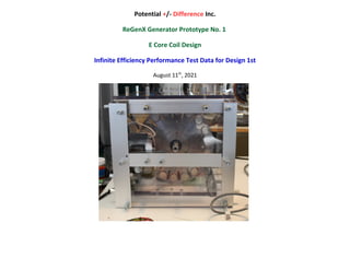
  • 1. Potential +/- Difference Inc. ReGenX Generator Prototype No. 1 E Core Coil Design Infinite Efficiency Performance Test Data for Design 1st August 11th , 2021
  • 2. ReGenX Generator Prototype No. 1 E Core Coil Design Prototype No. 1 employs a single conventional generator coil and a two ReGenX Generator coils which are would on the same E Core. The conventional generator coil is used to deliver electrical output power to the load and establish conventional generator performance, i.e.: 1. on-load Generator Armature Reaction (Generator Magnetic Field induced Counter-Electromagnetic-Torque/System Deceleration) and 2. to establish the conventional generator coil’s Load Current sine wave which can be observed on an oscilloscope. The ReGenX Generator coils are employed to establish ReGenX Generator performance, i.e.: 3. to reverse the conventional generator’s on-load Generator Armature Reaction/system deceleration, 4. to produce an on-load delayed Magnetic Field, induced Complementary-Electromagnetic-Torque/System Acceleration, 5. to demonstrate Flux Harvesting, 6. to establish the ReGenX Generator Coils’ Load Current Delay which can be observed simultaneously on the oscilloscope with the conventional generator coil’s non-delayed load current sine wave. Prototype No. 1 employs an induction motor prime mover, a tachometer and power analyzer to monitor prime mover input power variations from the steady state, equilibrium no-load conditions. Figure 1 Prototype No. 1.
  • 3. No-Load Conventional Generator All photo test data recorded in Table 1 FIGURE 2 No-Load, Steady State/Dynamic Equilibrium: Prototype No. 1 is brought up to a no-load steady state speed of 3482 RPM. A rotational equilibrium condition is established where the net drive shaft torque is zero and the mechanical drive shaft input power to the generator is also zero. On-Load Conventional Generator FIGURE 3 Generator Output Power: The conventional generator coil is placed on-load and delivers 11.4 Watts to the purely resistive load. FIGURE 4 On-Load, Reduced Steady State/Dynamic Equilibrium: On-load Generator Armature Reaction decelerates the prime mover and the prime mover induction motor responds by consuming additional stator current and power, additional torque is delivered to the generators drive shaft by the prime mover. 11.4 Watts is delivered to the load by the conventional generator and 18 Watts is required by the prime mover over the steady state no-load condition.  Conventional Generator Electrical Output = 11.4 Watts  Prime Mover Input Power Increase = + 18 Watts  On-Load System Speed Reduction = - 23 Rpm FIGURE 3 FIGURE 2 FIGURE 4
  • 4. CONVENTIONAL GENERATOR Prototype No. 1 E Core Coil Design Test Data Collection Date: March 20th , 2018 Test Data Collector Name/Organization: Mark Hamilton Chief Engineer GAL Power Systems Test Data Collection Location: Almonte ON Table 1 Recorded and Calculated Test Data CONVENTIONAL GENERATOR: Generator Condition Prime Mover INPUT Voltage (Volts) Prime Mover INPUT Current (Amps) Prime Mover INPUT Power Factor Prime Mover INPUT Power (Watts) System Equilibrium Speed Drive Shaft NET Torque = Zero (RPM) Conventiona l Generator OUTPUT (Volts) Conventional Generator OUTPUT Current (Amps) Load Power Factor Calculated Conventional Generator OUTPUT Load Power (Watts) Calculated Prime Mover On-Load INPUT INCREASE (Watts) No-Load 111.6 1.51 0.93 156 3482 - - - - - On-Load 111.5 1.68 0.93 174 3459 10.8 1.051 1 11.4 +18 Observation Notes: When the conventional generator coil is placed on-load from the steady state, no-load rotational equilibrium condition the generator delivers electrical output power to the load and the generator decelerates the system due to Generator Armature Reaction and additional input power is supplied by the prime mover. Test Data Collector Signature/Date: ____________________________________________________________________________
  • 5. No-Load ReGenX Generator All photo test data recorded in Table 2 FIGURE 5: Prototype No. 1 is brought up to a no-load steady state speed of 3482 RPM. A rotational equilibrium condition is established where the net drive shaft torque is zero and the mechanical drive shaft input power to the generator is also zero. On-Load ReGenX Generator Coil #1 FIGURE 6: The ReGenX Generator coil # 1 is placed on-load 13.0 Watts to the purely resistive load. FIGURE 7: On-load ReGenX Generator accelerates the prime mover and the prime mover induction motor responds by consuming a reduction in stator current and a reduction in power and reduced torque is delivered to the generators drive shaft by the prime mover. 13.3 Watts is delivered to the load by the ReGenX Generator coil #1 and a 4 Watt reduction is realized by the prime mover over the no-load steady state condition.  ReGenX Generator Coil #1 Electrical Output = 13.0 Watts  Prime Mover Input Power Reduction = - 4 Watts  On-Load System Speed Increase = + 8 RPM FIGURE 5 FIGURE 6 FIGURE 7
  • 6. On-Load ReGenX Generator Coil #1 & Coil #2 FIGURE 8: The ReGenX Generator coil # 2 is also placed on-load and delivers a total of 13.2 Watts to the purely resistive load. FIGURE 9: On-load ReGenX Generator Armature Reaction accelerates the prime mover and the prime mover induction motor responds by consuming a reduction in stator current and power, a reduction in torque is delivered to the generators drive shaft by the prime mover. 13.2 Watts is delivered to the load by the ReGenX Generaor coil #1 and Coil #2 and an 8 Watt reduction is realized by the prime mover over the steady state no-load condition.  ReGenX Generator Coil #1 Electrical OUTPUT = 13.2 Watts  Prime Mover Input Power Reduction = - 8 Watts  System Speed Increase = +13 RPM ReGenX Generator Flux Harvesting The discharging Delayed Magnetic Flux from the ReGenX Generator coils serves several functions: 1. it accelerates the on-load generator’s permanent magnet rotor (rotating magnetic field), 2. which accelerates the prime mover, 3. which reduces the prime mover’s on-load current and power consumption, 4. the discharging magnetic flux is collected in the conventional generator coil’s core, 5. which increases the core’s net flux change, thus increasing the induced voltage, current and power delivered across the load. FIGURE 8 FIGURE 9
  • 7. ReGenX Generator Prototype No. 1 E Core Coil Design Table 2 Recorded Data ReGenX GENERATOR Coil #1 & Coil #2: Generator Condition Prime Mover INPUT Voltage (Volts) Prime Mover INPUT Current (Amps) Prime Mover INPUT Power Factor Prime Mover INPUT Power (Watts) System Equilibrium Speed Drive Shaft NET Torque = Zero (RPM) ReGenX Generator OUTPUT (Volts) ReGenX Generator OUTPUT Current (Amps) Load Power Factor Calculated ReGenX Generator OUTPUT Load Power (Watts) Calculated Prime Mover On-Load INPUT DECREASE (Watts) No-Load 111.6 1.51 0.93 156 3482 - - - - - Coil #1 On-Load 112.1 1.49 0.91 149 3490 11.8 1.10 1 13.0 -4 Coil #2 On-Load 112.3 1.48 0.91 148 3495 11.9 1.11 1 13.2 -13 Observation Notes: When the ReGenX Generator coils are placed on-load from the steady state, no-load rotational equilibrium condition the conventional generator coil delivers power to the load, the ReGenX Generator coils accelerate the system due to Generator Armature Reaction reversal and a reduction in input power is realized by the prime mover. The more power delivered to the load in ReGenX Generator Mode, the more the system is accelerated and the more the prime mover input power consumption is reduced. Discharging magnetic flux by the ReGenX Generator coil accelerates the system and increases the voltage, current and power delivered to the load by the conventional generator coil due to Flux Harvesting. Test Data Collector Signature/Date: ____________________________________________________________________________
  • 8. Load Current Sine Waves On-Load Load Current Sine Waves Conventional Generator Coil and ReGenX Generator Coils FIGURE 10: The load current sine wave for the conventional coil (Green) is displayed on the oscilloscope and the Delayed Load Current for the ReGenX Generator coil #1(Purple) is also shown. Figure 11: The load current sine wave for the conventional coil (Green) is displayed on the oscilloscope and the Delayed Load Current for the ReGenX Generator coil #1 and coil #2 (Purple) is also shown. FIGURE 10 FIGURE 11
  • 9. ReGenX Generator Prototype No. 1 E Core Coil Design Table 3 Recorded Data ReGenX GENERATOR Load Current Sine Wave Delay: Generator Condition ReGenX Generator Coil 1 Load Current Delay (Degrees) ReGenX Generator Coil 2 Load Current Delay (Degrees) On-Load 47 degrees 108 degrees Test Data Collector Signature/Date: ____________________________________________________________________________
  • 10. Data Summary Conventional Generator Coil and ReGenX Generator Coils Table 1 & 2 Recorded and Calculated Data Summary CONVENTIONAL GENERATOR Coil and ReGenX GENERATOR Coil #1 & Coil #2: “Black Box” Efficiency Data Calculations Mechanical to Electrical Conversion Efficiencies Generator Type and Generator Condition Prime Mover INPUT Voltage (Volts) Prime Mover INPUT Current (Amps) Prime Mover INPUT Power Factor Prime Mover INPUT Power (Watts) System Equilibrium Speed Drive Shaft NET Torque = Zero (RPM) On-Load System Speed Response Decrease/ Increase (RPM) Generator OUTPUT (Volts) Generator OUTPUT Current (Amps) Load Power Factor Calculated Generator OUTPUT Load Power (Watts) Calculated Prime Mover On-Load Response INPUT Increase/ Decrease (Watts) No-Load 111.6 1.51 0.93 156 3482 - - - - - - Conventiona l Generator On-Load 111.5 1.68 0.93 174 3459 Decrease -23 10.8 1.051 1 11.4 +18 ReGenX Generator Coil #1 On-Load 112.1 1.49 0.91 149 3490 Increase +31 11.8 1.10 1 13.0 -4 Coil #2 On-Load 112.3 1.48 0.91 148 3495 Increase +36 11.9 1.11 1 13.2 -13
  • 11. Introduction: An electric generator is a machine that converts mechanical drive shaft input power to electrical output power. At any operational No-Load, Steady State Speed or Rotational Equilibrium condition the drive shaft’s Mechanical Input Power (Pin) to the generator is always 0.00 Watts because; Mechanical Drive Shaft Input Power (P) = Net Torque(T) x System Rotational Speed(ω): Pin = T x ω Because T(net) = 0.00 at Rotational Equilibrium Mechanical Drive Shaft Input Power (Pin) on No-Load always equals 0.00 Watts When the generator is placed on load the drive shaft’s mechanical input power is provided by the prime mover, which must always be increased (due to Generator Armature Reaction) in order to deliver power to the load or the system will stall. For example; If the generator delivered 9 Watts to the load and the prime mover input increased by 10 Watts the “Black Box” System Efficiency would be: Generator Conversion Efficiency = Output/Input x 100 or 9/10 x 100 = 90% Black Box Conversion Efficiency What is Rotational Equilibrium? The concept of rotational equilibrium is an equivalent to Newton’s 1ˢᵗ law for a rotational system. An object which is not rotating remains not rotating unless acted on by an external torque. Similarly, an object rotating at constant angular velocity remains rotating unless acted on by an external torque. In this case it is the net torque which is important. If the net torque on a rotatable object is zero then it will be in rotational equilibrium and not able to acquire angular acceleration. https://www.khanacademy.org/science/physics/torque-angular- momentum/torque-tutorial/a/torque
  • 12. “Black Box” Efficiency Data Calculations Mechanical to Electrical Conversion Efficiencies If the generator delivered 5 Watts to the load and the prime mover input increased by 10 Watts the Black Box System Efficiency would be: 5/10 x 100 = 50% Conversion Efficiency If the generator delivered 10 Watts to the load and the prime mover input increased by 10 Watts the Black Box System Efficiency would be: 10/10 x 100 = 100% Conversion Efficiency If the generator delivered 10 Watts to the load and the prime mover input increased by 0 Watts (in other words did not increase at all or was reduced to below the no-load idle input condition of 0 Watts), the Black Box System Efficiency would be: 10/0 x 100 = Infinite % Conversion Efficiency Actual Generator Conversion Efficiency The Actual Generator Conversion Efficiency would be the Prime Mover Input Increase (Watts) x Prime Mover (induction motor) Electrical to Mechanical Conversion Efficiency (%) which would be about 85% for the induction motor prime movers used and the speed of operation. All of the tests in this document are operated at identical, torques and speeds and from an initial operating no-load, Rotational Equilibrium condition where the mechanical input power is always 0.00 Watts
  • 13. Black Box System Efficiency Calculations ReGenX GENERATOR Table 9 Calculated Data Black Box System Efficiency ReGenX Generator Device Type Drive Shaft Net Torque at Equilibrium (Nm) Calculated Drive Shaft INPUT POWER No-Load/ Equilibrium P = Tnet x Speed (Watts) INPUT Calculated On-Load Prime Mover Decrease (Watts) Drive Shaft Torque Decrease (Nm) OUTPUT Calculated Load Power (Watts) BLACK BOX EFFICIENCY Calculated System Efficiency Output/Input x 100 (%) ReGenX Generator Coil #1 Prototype #1 0.00 0.00 -3 - 0.008 12.9 ∞ ReGenX Generator Coil #2 Prototype #1 0.00 0.00 -7 -0.02 13.2 ∞ Torque = KW x 9550/RPM
  • 14. Black Box System Efficiency Calculations CONVENTIONAL GENERATOR and ReGenX GENERATOR Table 10 Calculated Data Black Box System Efficiency CONVENTIONAL GENERATOR and ReGenX GENERATOR Device Type Drive Shaft Net Torque at Equilibrium (Nm) Calculated Drive Shaft INPUT POWER No-Load/ Equilibrium P = Tnet x Speed (Watts) INPUT Calculated On-Load Prime Mover Increase/Decrease (Watts) Drive Shaft Torque Increase/Decrease (Nm) OUTPUT Calculated Load Power (Watts) BLACK BOX Calculated System EFFICIENCY Output/Input x 100 (%) Conventional Generator Coil Prototype #1 0.00 0.00 +20 + 0.06 11.1 > 55.5% ReGenX Generator Coil #1 Prototype #1 0.00 0.00 -3 -0.008 12.9 ∞ ReGenX Generator Coil #2 Prototype #1 0.00 0.00 -7 -0.02 13.2 ∞ Test Data Calculator Signature/Date: ____________________________________________________________________________
  • 15. Data and Efficiency Summaries ReGenX GENERATOR Table 12 Calculated Data Black Box System Efficiency Conventional Generator, and ReGenX Generator, Device Type Drive Shaft Net Torque at Equilibrium (Nm) Calculated Mechanical Drive Shaft INPUT POWER No-Load / Equilibrium P = Tnet x Speed (Watts) INPUT Calculated Prime Mover On-Load Increase (Watts) Drive Shaft Torque Increase/Decrease (Nm) OUTPUT Calculated Load Power (Watts) Black Box Calculated System EFFICIENCY Output/Input x 100 (%) Conventional Generator Coil Prototype #1 0.00 0.00 +20 + 0.06 11.1 > 55.5% ReGenX Generator Coil #1 Prototype #1 0.00 0.00 -3 -0.008 12.9 ∞ ReGenX Generator Coil #2 Prototype #1 0.00 0.00 -7 -0.02 13.2 ∞
  • 16. Conclusions Performance data for a conventional generator and conventional generator/transformer were presented. All Conventional generators and transformers operate at below 100% efficiency in their conversions of mechanical drive shaft input power to electrical output power. Performance data for a ReGenX Generator, Bi-Toroid Transformer and an EV Regenerative Acceleration (ReGenX) Generator were also presented. The ReGenX Generator, Bi-Toroid Transformer and EV Regenerative Acceleration (ReGenX) Generator all operate with a Load Current Delay which allows them to require a 0.00 Watt prime mover input increase (infinite efficiency) when placed on-load and when delivering power to the load. Conventional Generator Armature Reaction, Counter-Electromagnetic-Torque/system deceleration has now been replaced with ReGenX Generator Delayed Armature Reaction, Complementary-Electromagnetic-Torque/system acceleration. Electric Power Generation Applications The ReGenX Generator and Bi-Toroid innovation technologies now allow for electric power generation with less mechanical input power to be supplied to the generator on-load than is required at idle on no-load. This translates to more than a 80% reduction in input costs and 80% less output pollution and more than an 80% cost of purchasing electricity to the consumer. Electric Vehicle Applications The Electric Vehicle (EV) Regenerative Acceleration (ReGenX) Generator now allows electric vehicle generators to recharge the EV’s batteries while simultaneously accelerating the EV above a certain speed and also to recharge the EV’s batteries while simultaneously decelerating the EV below a certain speed. The greater the magnitude of battery recharging in EV Regenerative Acceleration Mode the faster the rate of battery recharging and the faster the rate of EV acceleration. The greater the magnitude of battery recharging in EV regenerative braking mode the faster the rate of battery recharging and the faster the rate of EV deceleration. The magnitude of battery recharging current supplied by the ReGenX Generator in EV Regenerative Acceleration Mode is limited only by the physical size of the ReGen-X Motor used.