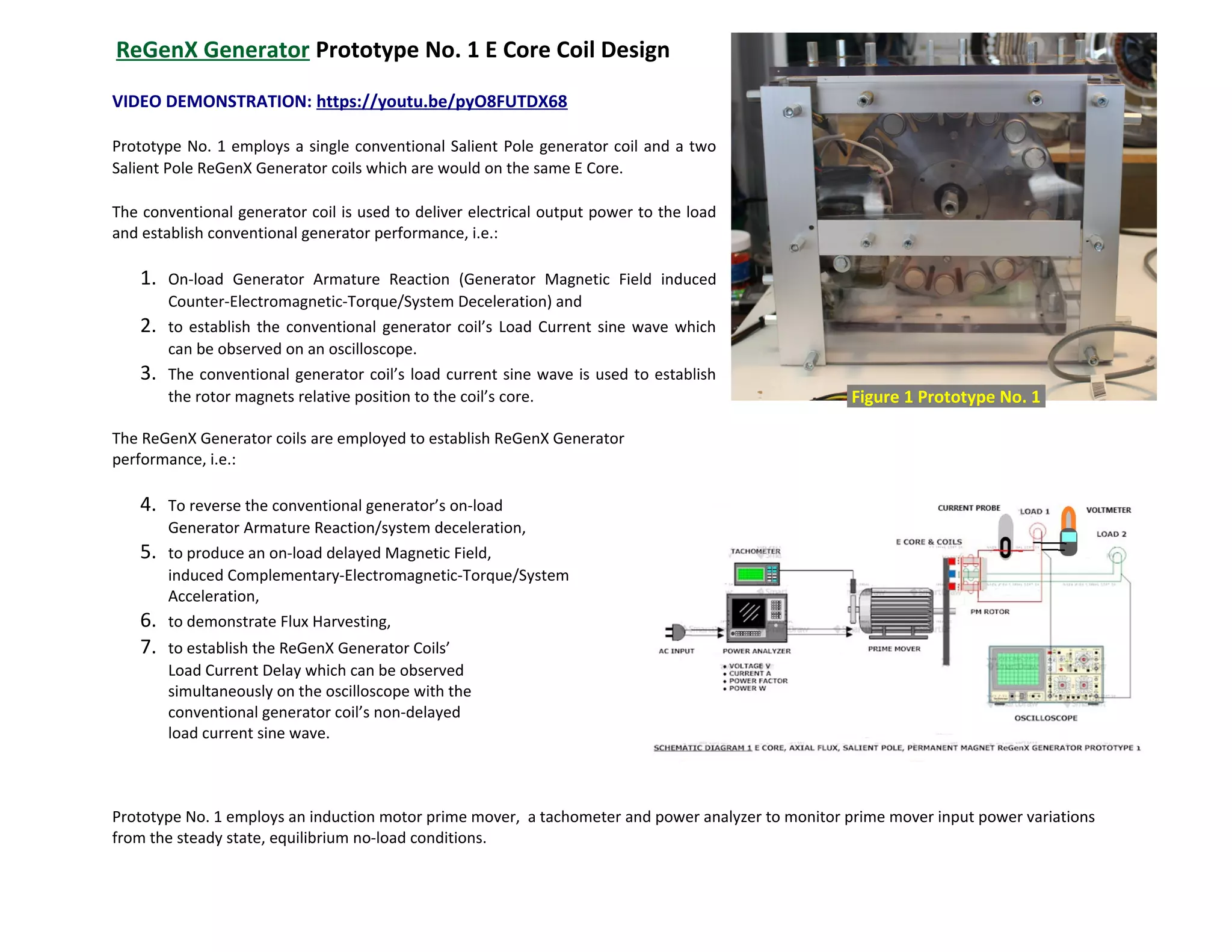
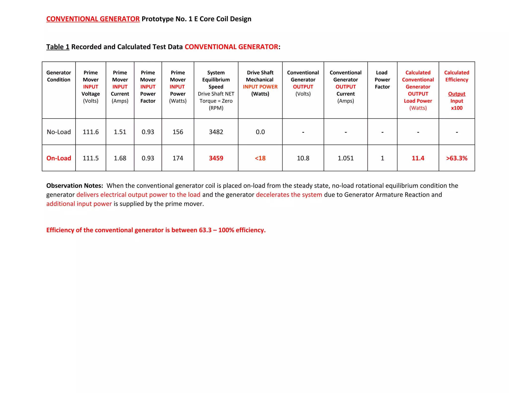
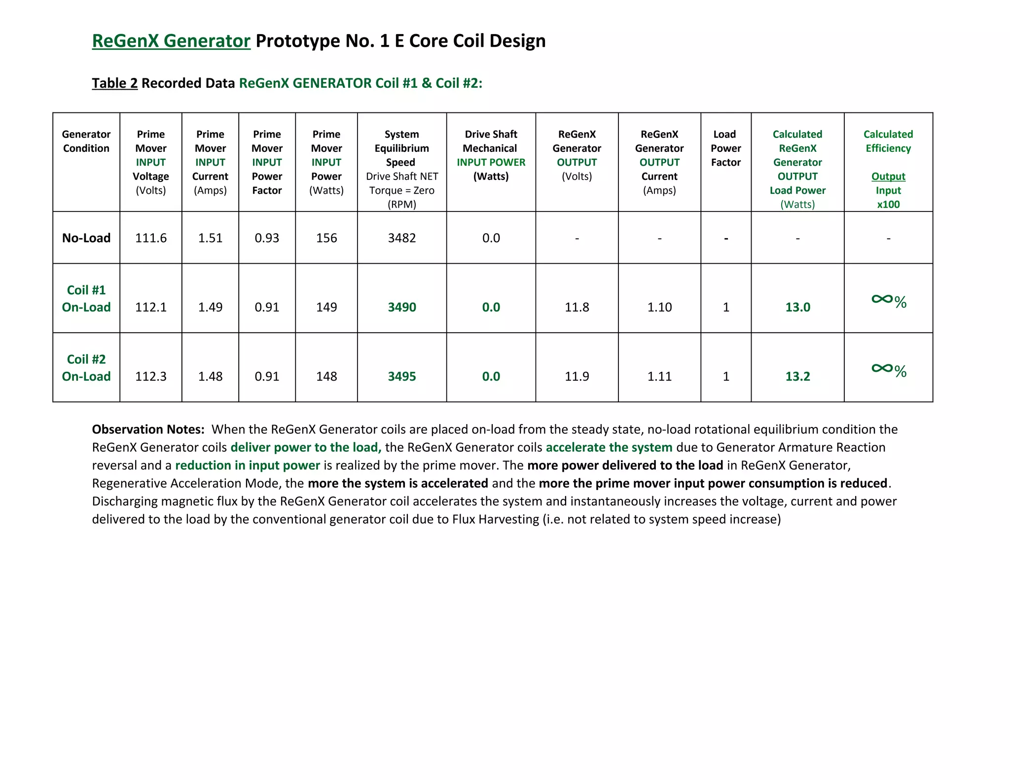
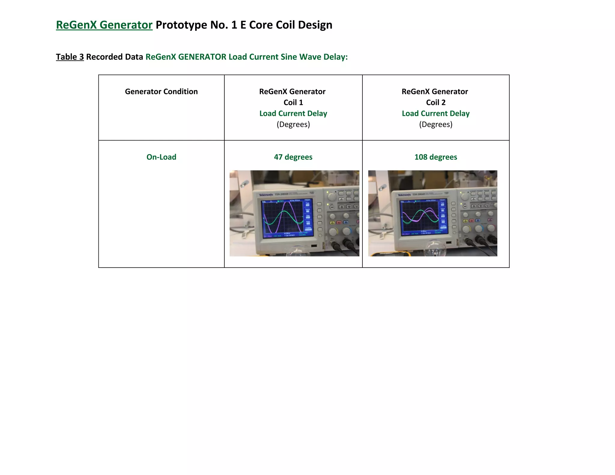
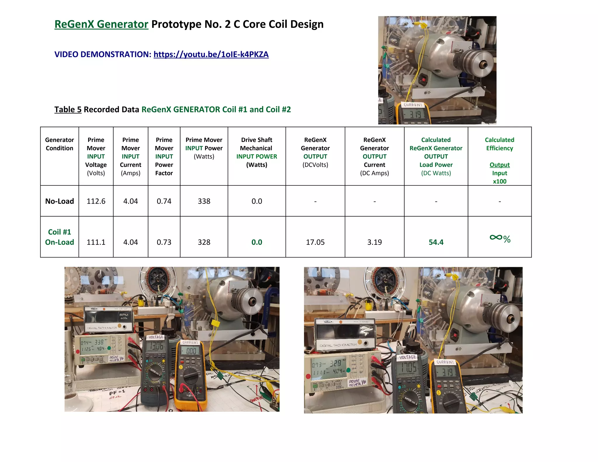
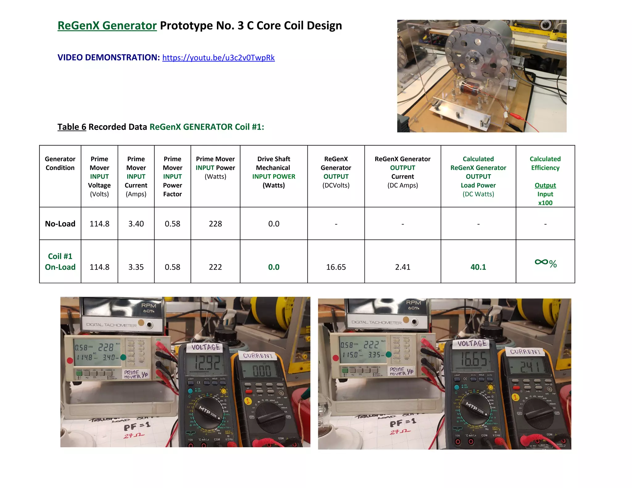
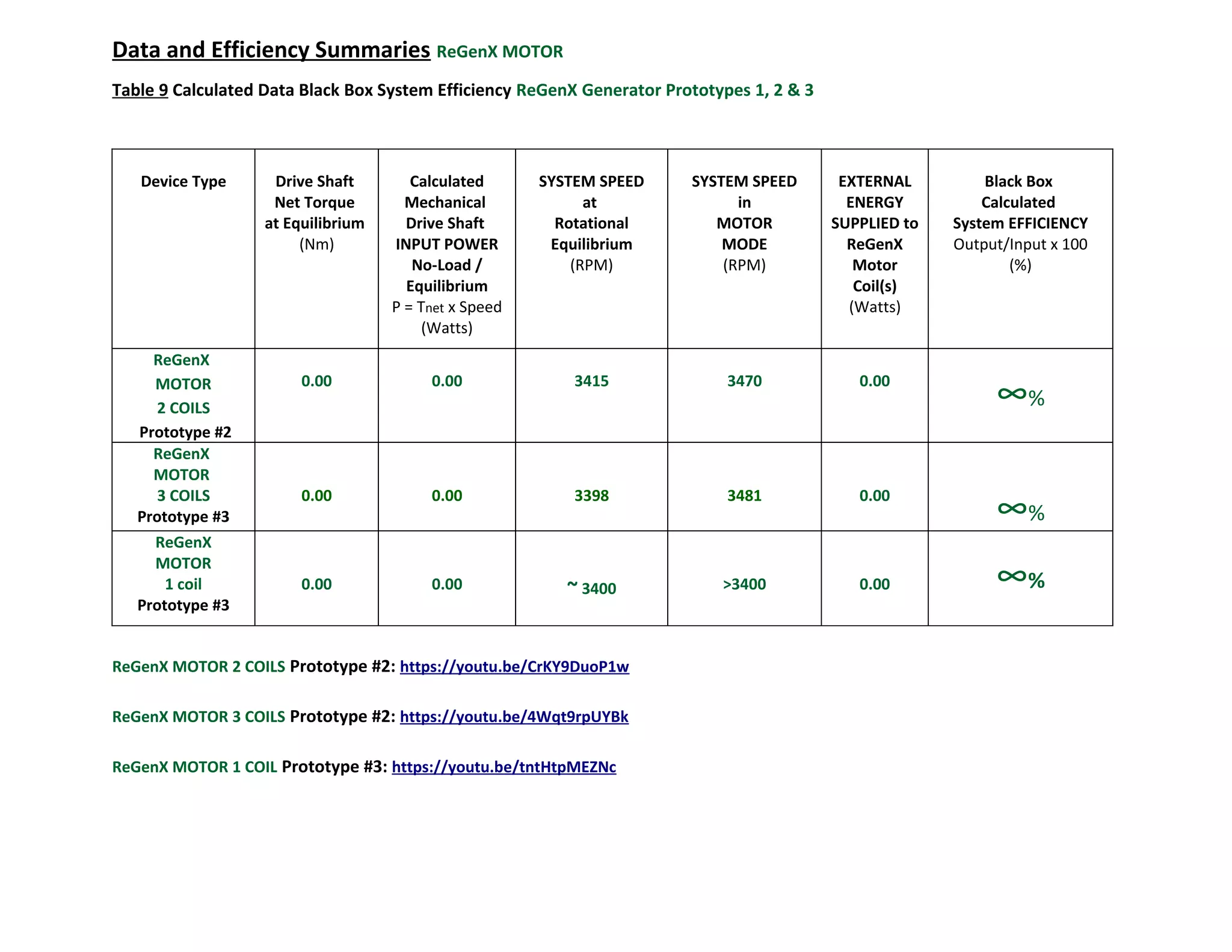
Thane C. Heins
President and CEO
Potential +/- Difference inc.
Pioneering Electric Vehicle Regenerative Acceleration and Charging Ahead...
“You never change things by fighting the existing reality.
To change something, build a new model that makes the existing model obsolete.”
― Buckminster Fuller
Structural Analysis and Design of Foundations: A Comprehensive Handbook for S...
ReGenX Generator & Motor Prototypes 1, 2, & 3 for Performance Confirmation
1. ReGenX Generator Prototype No. 1 E Core Coil Design
VIDEO DEMONSTRATION: https://youtu.be/pyO8FUTDX68
Prototype No. 1 employs a single conventional Salient Pole generator coil and a two
Salient Pole ReGenX Generator coils which are would on the same E Core.
The conventional generator coil is used to deliver electrical output power to the load
and establish conventional generator performance, i.e.:
1. On-load Generator Armature Reaction (Generator Magnetic Field induced
Counter-Electromagnetic-Torque/System Deceleration) and
2. to establish the conventional generator coil’s Load Current sine wave which
can be observed on an oscilloscope.
3. The conventional generator coil’s load current sine wave is used to establish
the rotor magnets relative position to the coil’s core.
The ReGenX Generator coils are employed to establish ReGenX Generator
performance, i.e.:
4. To reverse the conventional generator’s on-load
Generator Armature Reaction/system deceleration,
5. to produce an on-load delayed Magnetic Field,
induced Complementary-Electromagnetic-Torque/System
Acceleration,
6. to demonstrate Flux Harvesting,
7. to establish the ReGenX Generator Coils’
Load Current Delay which can be observed
simultaneously on the oscilloscope with the
conventional generator coil’s non-delayed
load current sine wave.
Prototype No. 1 employs an induction motor prime mover, a tachometer and power analyzer to monitor prime mover input power variations
from the steady state, equilibrium no-load conditions.
Figure 1 Prototype No. 1.
2. CONVENTIONAL GENERATOR Prototype No. 1 E Core Coil Design
Table 1 Recorded and Calculated Test Data CONVENTIONAL GENERATOR:
Generator
Condition
Prime
Mover
INPUT
Voltage
(Volts)
Prime
Mover
INPUT
Current
(Amps)
Prime
Mover
INPUT
Power
Factor
Prime
Mover
INPUT
Power
(Watts)
System
Equilibrium
Speed
Drive Shaft NET
Torque = Zero
(RPM)
Drive Shaft
Mechanical
INPUT POWER
(Watts)
Conventional
Generator
OUTPUT
(Volts)
Conventional
Generator
OUTPUT
Current
(Amps)
Load
Power
Factor
Calculated
Conventional
Generator
OUTPUT
Load Power
(Watts)
Calculated
Efficiency
Output
Input
x100
No-Load 111.6 1.51 0.93 156 3482 0.0 - - - - -
On-Load 111.5 1.68 0.93 174 3459 <18 10.8 1.051 1 11.4 >63.3%
Observation Notes: When the conventional generator coil is placed on-load from the steady state, no-load rotational equilibrium condition the
generator delivers electrical output power to the load and the generator decelerates the system due to Generator Armature Reaction and
additional input power is supplied by the prime mover.
Efficiency of the conventional generator is between 63.3 – 100% efficiency.
3. ReGenX Generator Prototype No. 1 E Core Coil Design
Table 2 Recorded Data ReGenX GENERATOR Coil #1 & Coil #2:
Generator
Condition
Prime
Mover
INPUT
Voltage
(Volts)
Prime
Mover
INPUT
Current
(Amps)
Prime
Mover
INPUT
Power
Factor
Prime
Mover
INPUT
Power
(Watts)
System
Equilibrium
Speed
Drive Shaft NET
Torque = Zero
(RPM)
Drive Shaft
Mechanical
INPUT POWER
(Watts)
ReGenX
Generator
OUTPUT
(Volts)
ReGenX
Generator
OUTPUT
Current
(Amps)
Load
Power
Factor
Calculated
ReGenX
Generator
OUTPUT
Load Power
(Watts)
Calculated
Efficiency
Output
Input
x100
No-Load 111.6 1.51 0.93 156 3482 0.0 - - - - -
Coil #1
On-Load 112.1 1.49 0.91 149 3490 0.0 11.8 1.10 1 13.0 ∞%
Coil #2
On-Load 112.3 1.48 0.91 148 3495 0.0 11.9 1.11 1 13.2 ∞%
Observation Notes: When the ReGenX Generator coils are placed on-load from the steady state, no-load rotational equilibrium condition the
ReGenX Generator coils deliver power to the load, the ReGenX Generator coils accelerate the system due to Generator Armature Reaction
reversal and a reduction in input power is realized by the prime mover. The more power delivered to the load in ReGenX Generator,
Regenerative Acceleration Mode, the more the system is accelerated and the more the prime mover input power consumption is reduced.
Discharging magnetic flux by the ReGenX Generator coil accelerates the system and instantaneously increases the voltage, current and power
delivered to the load by the conventional generator coil due to Flux Harvesting (i.e. not related to system speed increase)
4. ReGenX Generator Prototype No. 1 E Core Coil Design
Table 3 Recorded Data ReGenX GENERATOR Load Current Sine Wave Delay:
Generator Condition ReGenX Generator
Coil 1
Load Current Delay
(Degrees)
ReGenX Generator
Coil 2
Load Current Delay
(Degrees)
On-Load 47 degrees 108 degrees
5. Data Summary Conventional Generator Coil and ReGenX Generator Coils
Table 4 Recorded and Calculated Data Summary CONVENTIONAL GENERATOR Coil and ReGenX GENERATOR Coil #1 & Coil #2:
VIDEO DEMONSTRATION: https://youtu.be/pyO8FUTDX68
Generator
Type
and
Generator
Condition
Prime
Mover
INPUT
Voltage
(Volts)
Prime
Mover
INPUT
Current
(Amps)
Prime
Mover
INPUT
Power
Factor
Prime
Mover
INPUT
Power
(Watts)
System
Equilibrium
Speed
Drive Shaft NET
Torque = Zero
(RPM)
Drive Shaft
Mechanical
INPUT
POWER
(Watts)
Generator
OUTPUT
(Volts)
Generator
OUTPUT
Current
(Amps)
Load
Power
Factor
Calculated
Generator
OUTPUT
Load
Power
(Watts)
Calculated
Efficiency
Output
Input
x100
No-Load 111.6 1.51 0.93 156 3482 0.00 - - - - -
Conventional
Generator
On-Load
111.5 1.68 0.93 174 3459 <18 10.8 1.051 1 11.4 >63.3%
ReGenX
Generator
Coil #1
On-Load
112.1 1.49 0.91 149 3490 0.00 11.8 1.10 1 13.0
∞%
Coil #2
On-Load 112.3 1.48 0.91 148 3495 0.00 11.9 1.11 1 13.2
∞%
6. ReGenX Generator Prototype No. 2 C Core Coil Design
VIDEO DEMONSTRATION: https://youtu.be/1oIE-k4PKZA
Table 5 Recorded Data ReGenX GENERATOR Coil #1 and Coil #2
Generator
Condition
Prime
Mover
INPUT
Voltage
(Volts)
Prime
Mover
INPUT
Current
(Amps)
Prime
Mover
INPUT
Power
Factor
Prime Mover
INPUT Power
(Watts)
Drive Shaft
Mechanical
INPUT POWER
(Watts)
ReGenX
Generator
OUTPUT
(DCVolts)
ReGenX
Generator
OUTPUT
Current
(DC Amps)
Calculated
ReGenX Generator
OUTPUT
Load Power
(DC Watts)
Calculated
Efficiency
Output
Input
x100
No-Load 112.6 4.04 0.74 338 0.0 - - - -
Coil #1
On-Load 111.1 4.04 0.73 328 0.0 17.05 3.19 54.4 ∞%
7. ReGenX Generator Prototype No. 3 C Core Coil Design
VIDEO DEMONSTRATION: https://youtu.be/u3c2v0TwpRk
Table 6 Recorded Data ReGenX GENERATOR Coil #1:
Generator
Condition
Prime
Mover
INPUT
Voltage
(Volts)
Prime
Mover
INPUT
Current
(Amps)
Prime
Mover
INPUT
Power
Factor
Prime Mover
INPUT Power
(Watts)
Drive Shaft
Mechanical
INPUT POWER
(Watts)
ReGenX
Generator
OUTPUT
(DCVolts)
ReGenX Generator
OUTPUT
Current
(DC Amps)
Calculated
ReGenX Generator
OUTPUT
Load Power
(DC Watts)
Calculated
Efficiency
Output
Input
x100
No-Load 114.8 3.40 0.58 228 0.0 - - - -
Coil #1
On-Load 114.8 3.35 0.58 222 0.0 16.65 2.41 40.1 ∞%
8. Black Box System Efficiency Calculations CONVENTIONAL GENERATOR and ReGenX GENERATOR
Table 7 Calculated Data Black Box System Efficiency CONVENTIONAL GENERATOR and ReGenX GENERATOR
Device Type Drive Shaft
Net Torque
at
Equilibrium
(Nm)
Calculated
Drive Shaft
INPUT POWER
No-Load/
Equilibrium
P = Tnet x Speed
(Watts)
INPUT
Calculated
On-Load
Prime Mover
Increase/Decrease
(Watts)
Prime Mover
Supplied
Drive Shaft
Torque
Increase/Decrease
(Nm)
OUTPUT
Calculated
Load Power
(Watts)
BLACK BOX Calculated
System EFFICIENCY
Output/Input x 100
(%)
Conventional
Generator Coil
Prototype #1
0.00 0.00 +18 + 0.06 11.4 >63.3%
ReGenX
Generator Coil
#1
Prototype #1
0.00 0.00 -4 -0.01 13.0 ∞%
ReGenX
Generator Coil
#2
Prototype #1
0.00 0.00 -13 -0.04 13.2 ∞%
9. Data and Efficiency Summaries ReGenX GENERATOR
Table 8 Calculated Data Black Box System Efficiency ReGenX Generator Prototypes 1, 2 & 3
Device Type Drive Shaft
Net Torque
at Equilibrium
(Nm)
Calculated
Mechanical
Drive Shaft
INPUT POWER
No-Load /
Equilibrium
P = Tnet x Speed
(Watts)
INPUT
Calculated
Prime Mover
On-Load Increase
(Watts)
Prime Mover
Supplied
Drive Shaft
Torque
Increase/Decrease
(Nm)
OUTPUT
Calculated
Load Power
(Watts)
Black Box
Calculated
System EFFICIENCY
Output/Input x 100
(%)
Conventional
Generator Coil
Prototype #1
0.00 0.00 +18 + 0.06 11.4 >63.3%
ReGenX
Generator Coil #1
Prototype #1 0.00 0.00 -4 0.00 13.0 ∞%
ReGenX
Generator Coil #2
Prototype #1 0.00 0.00 -13 0.00 13.2 ∞%
ReGenX
Generator
Coil #1 & #2
On-Load
Prototype #2
0.00 0.00 -10 0.00 54.4
∞%
Coil #1
On-Load
Prototype #3
0.00 0.00 -6 0.00 40.1 ∞%
10. ReGenX MOTOR Prototype No. 2 C Core Coil Design
2 COIL PROTOTYPE
VIDEO DEMONSTRATION: https://youtu.be/CrKY9DuoP1w
INITIAL INDUCTION MOTOR IDLE SPEED = 3415 RPM
FINAL INDUCTION MOTOR SPEED = 3470 RPM
TOTAL SPEED INCREASE = 76 RPM
INITIAL NDUCTION MOTOR POWER CONSUMPTION = 373 WATTS
FINAL INDUCTION MOTOR POWER CONSUMPTION = 297 WATTS
TOTAL POWER CONSUMPTION REDUCTION = 76 WATTS
TOTAL CURRENT = 3.9 AMPS
TOTAL COIL RESISTANCE = 0.25 OHMS
TOTAL CREATED ENERGY = 3.8 WATTS
EXTERNAL INPUT POWER APPLIED = 0.0 WATTS
EFFICIENCY = INFINITY
3 COIL PROTOTYPE
VIDEO DEMONSTRATION: https://youtu.be/4Wqt9rpUYBk
INITIAL INDUCTION MOTOR IDLE SPEED = 3398 RPM
FINAL INDUCTION MOTOR SPEED = 3481 RPM
TOTAL SPEED INCREASE = 83 RPM
INITIAL NDUCTION MOTOR POWER CONSUMPTION = 433 WATTS
FINAL INDUCTION MOTOR POWER CONSUMPTION = 327 WATTS
TOTAL POWER CONSUMPTION REDUCTION = 106 WATTS
TOTAL CURRENT = 5.9 AMPS
TOTAL COIL RESISTANCE = 0.25 OHMS
TOTAL ENERGY CREATED = 5.2 WATTS
EXTERNAL INPUT POWER APPLIED = 0.0 WATTS
EFFICIENCY = INFINITY
11. ReGenX MOTOR Prototype No. 3 C Core Coil Design
1 COIL PROTOTYPE
VIDEO DEMONSTRATION: https://youtu.be/tntHtpMEZNc
INITIAL INDUCTION MOTOR IDLE SPEED =
FINAL INDUCTION MOTOR SPEED =
TOTAL SPEED INCREASE =
INITIAL NDUCTION MOTOR POWER CONSUMPTION = 322 WATTS
FINAL INDUCTION MOTOR POWER CONSUMPTION = 263 WATTS
TOTAL POWER CONSUMPTION REDUCTION = 59 WATTS
TOTAL CURRENT = 3.04 AMPS
TOTAL COIL RESISTANCE = 0.4 OHMS
TOTAL CREATED ENERGY = 3.69 WATTS
EXTERNAL INPUT POWER APPLIED = 0.0 WATTS
EFFICIENCY = INFINITY
12. Data and Efficiency Summaries ReGenX MOTOR
Table 9 Calculated Data Black Box System Efficiency ReGenX Generator Prototypes 1, 2 & 3
Device Type Drive Shaft
Net Torque
at Equilibrium
(Nm)
Calculated
Mechanical
Drive Shaft
INPUT POWER
No-Load /
Equilibrium
P = Tnet x Speed
(Watts)
SYSTEM SPEED
at
Rotational
Equilibrium
(RPM)
SYSTEM SPEED
in
MOTOR
MODE
(RPM)
EXTERNAL
ENERGY
SUPPLIED to
ReGenX
Motor
Coil(s)
(Watts)
Black Box
Calculated
System EFFICIENCY
Output/Input x 100
(%)
ReGenX
MOTOR
2 COILS
Prototype #2
0.00 0.00 3415 3470 0.00
∞%
ReGenX
MOTOR
3 COILS
Prototype #3
0.00 0.00 3398 3481 0.00
∞%
ReGenX
MOTOR
1 coil
Prototype #3
0.00 0.00 ~ 3400 >3400 0.00 ∞%
ReGenX MOTOR 2 COILS Prototype #2: https://youtu.be/CrKY9DuoP1w
ReGenX MOTOR 3 COILS Prototype #2: https://youtu.be/4Wqt9rpUYBk
ReGenX MOTOR 1 COIL Prototype #3: https://youtu.be/tntHtpMEZNc