
Download as PDF, PPTX
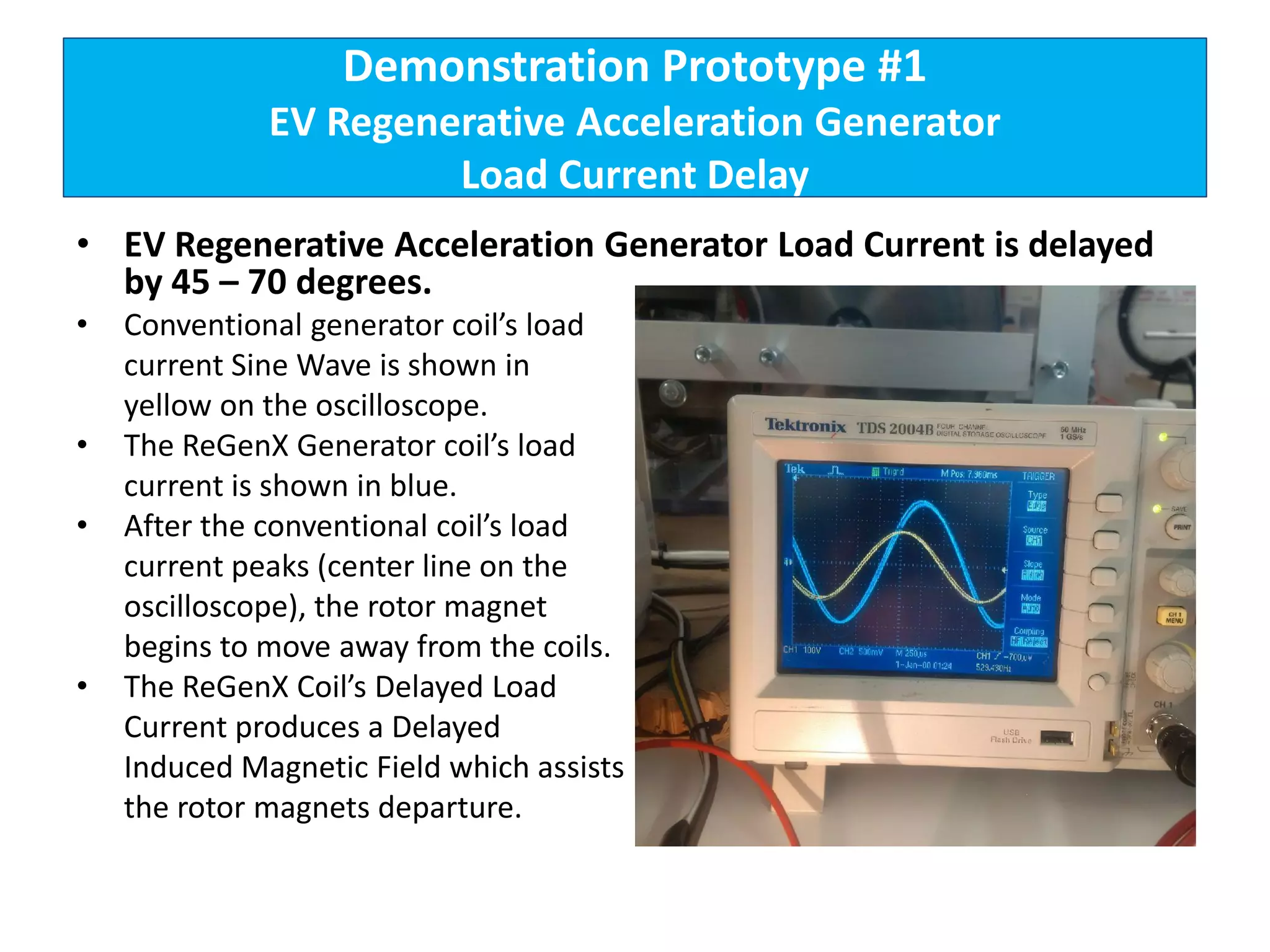
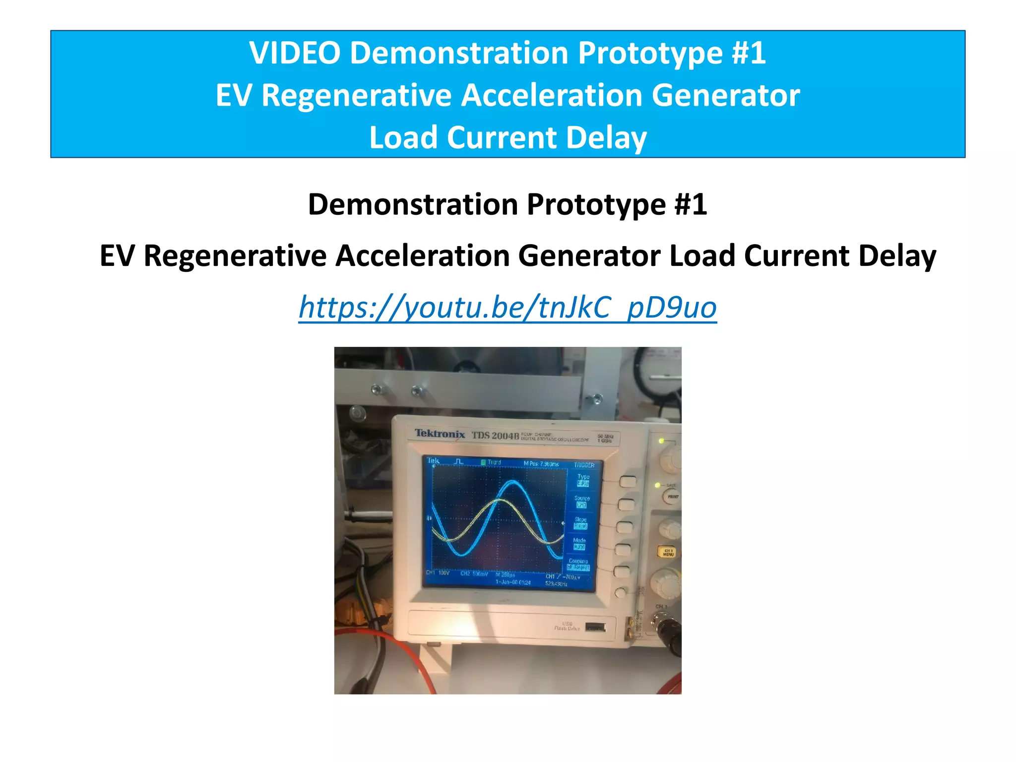
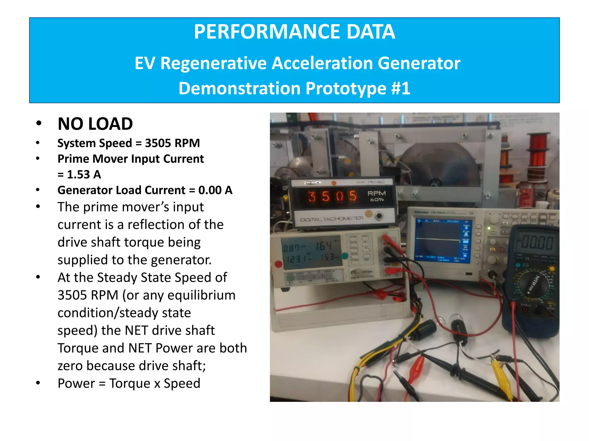
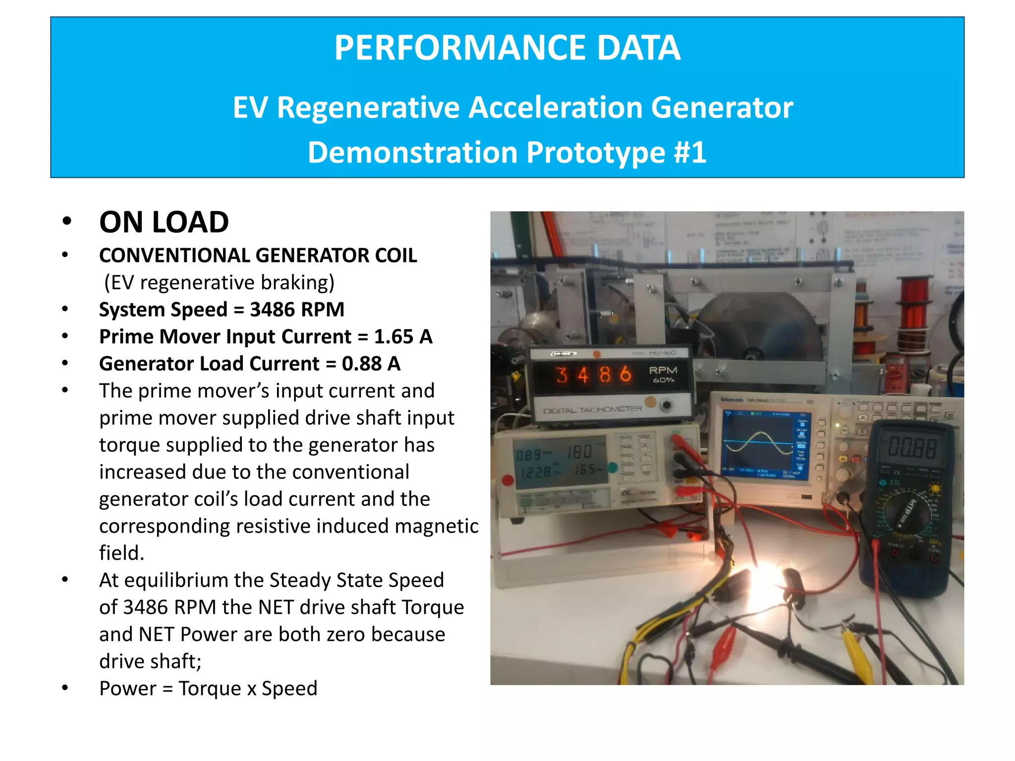
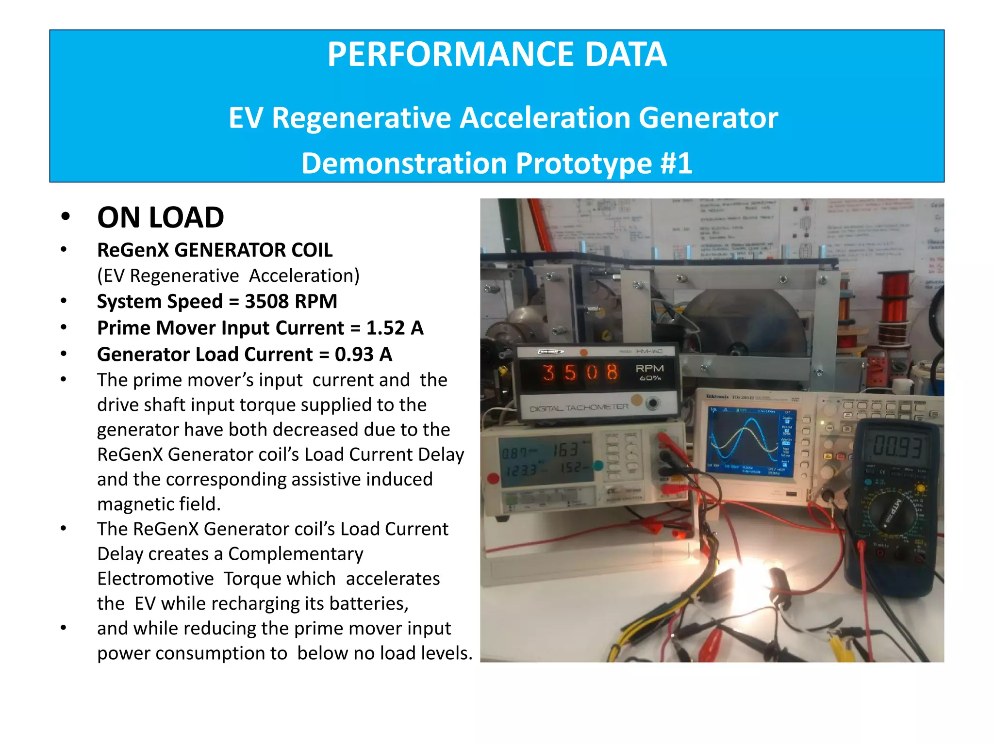
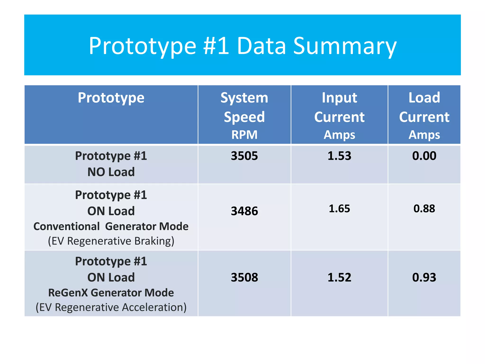
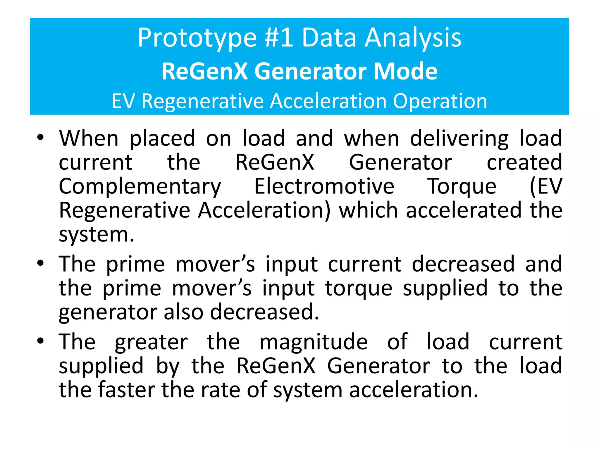
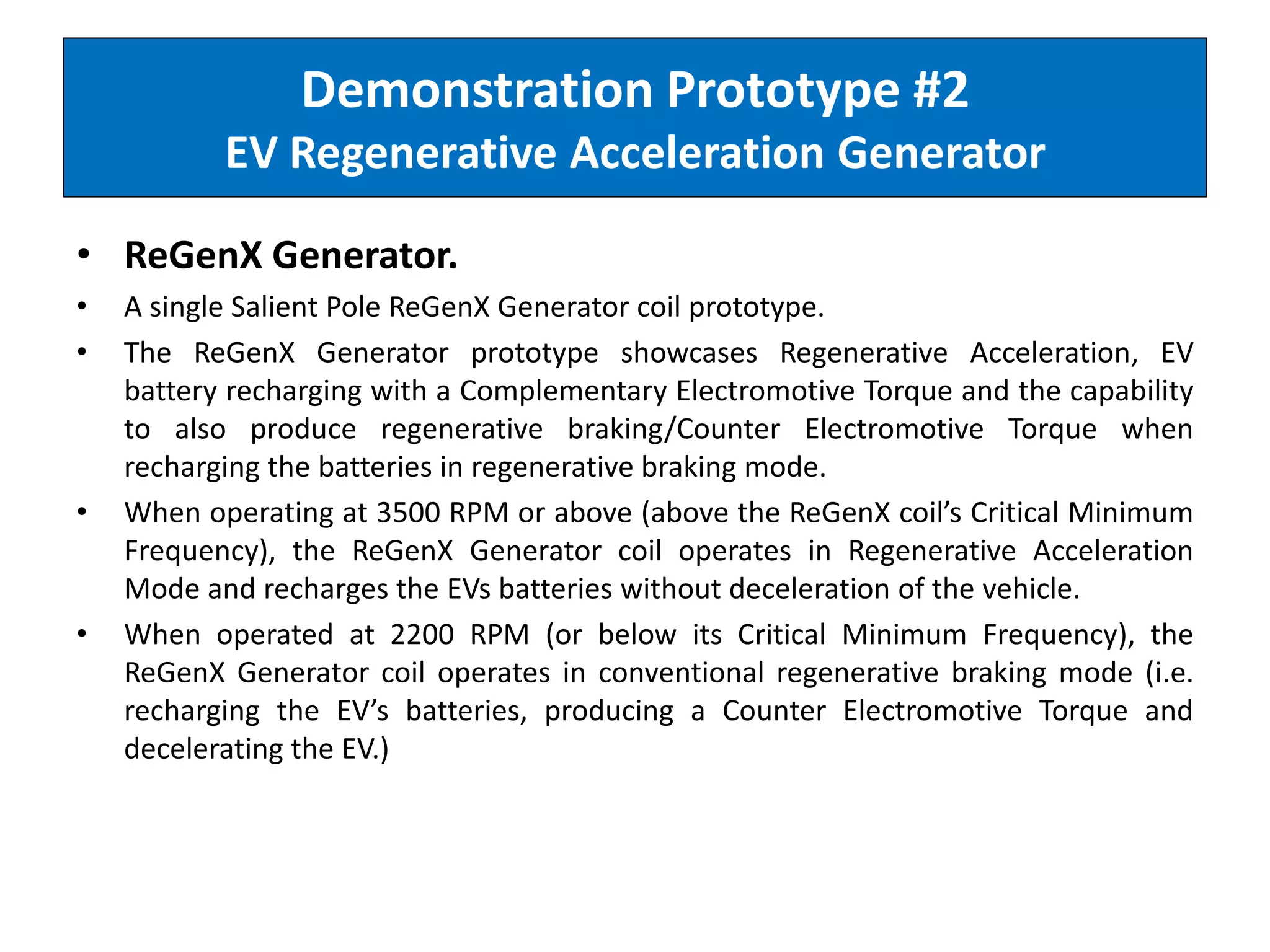
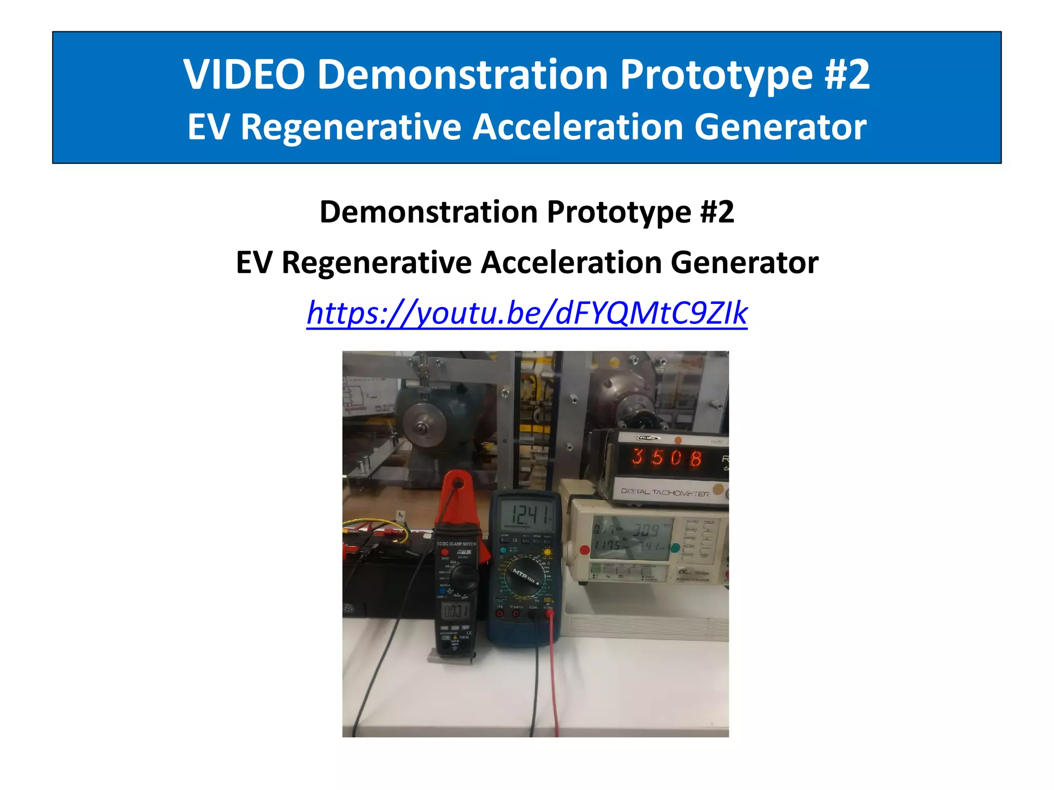
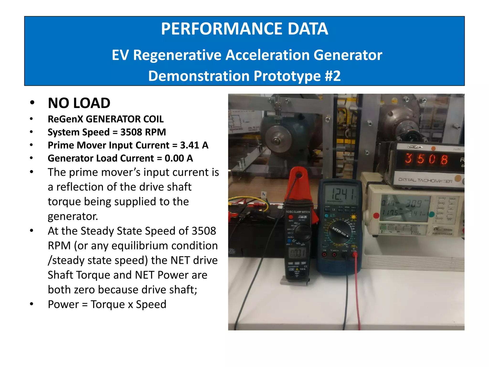
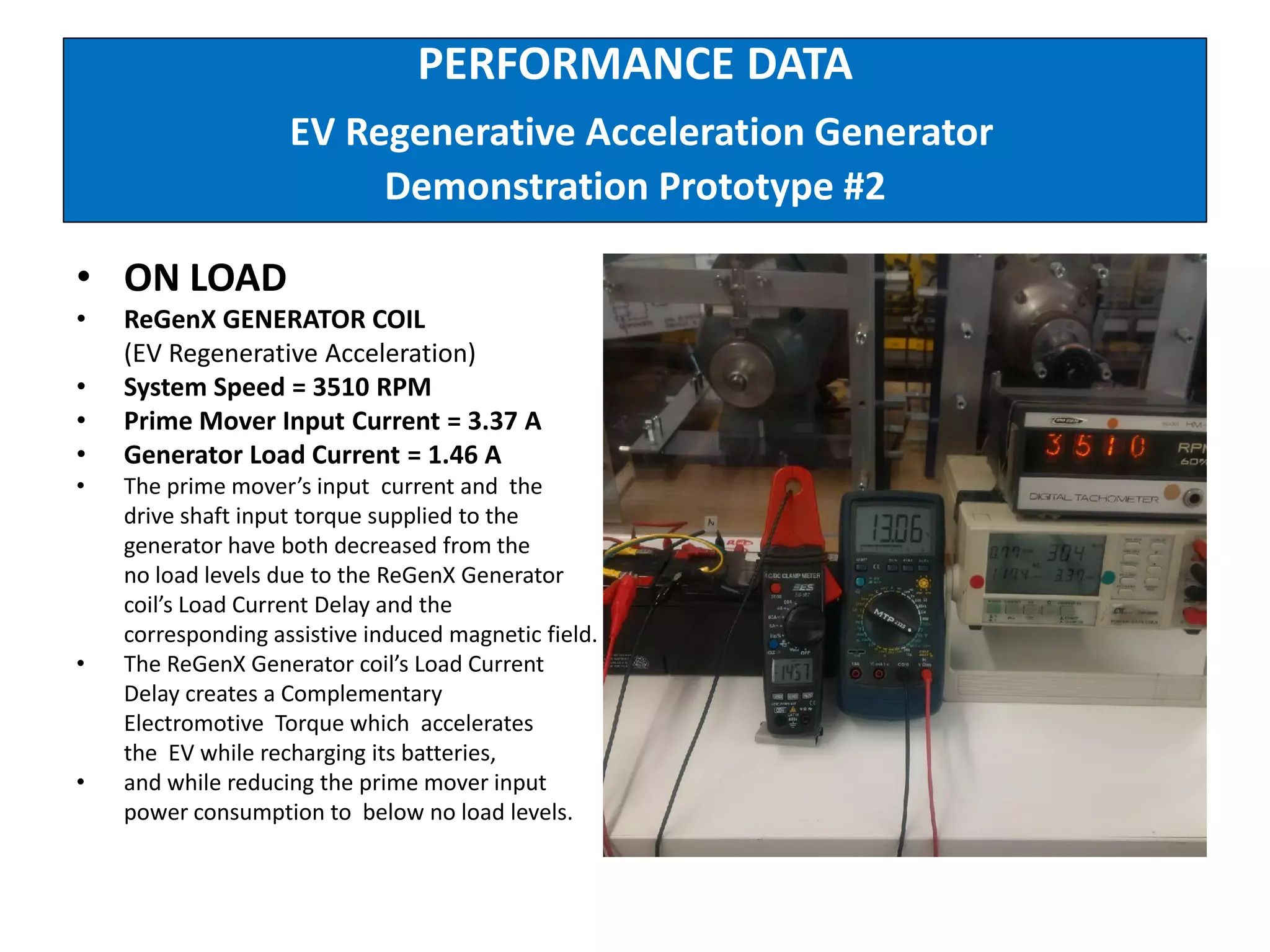
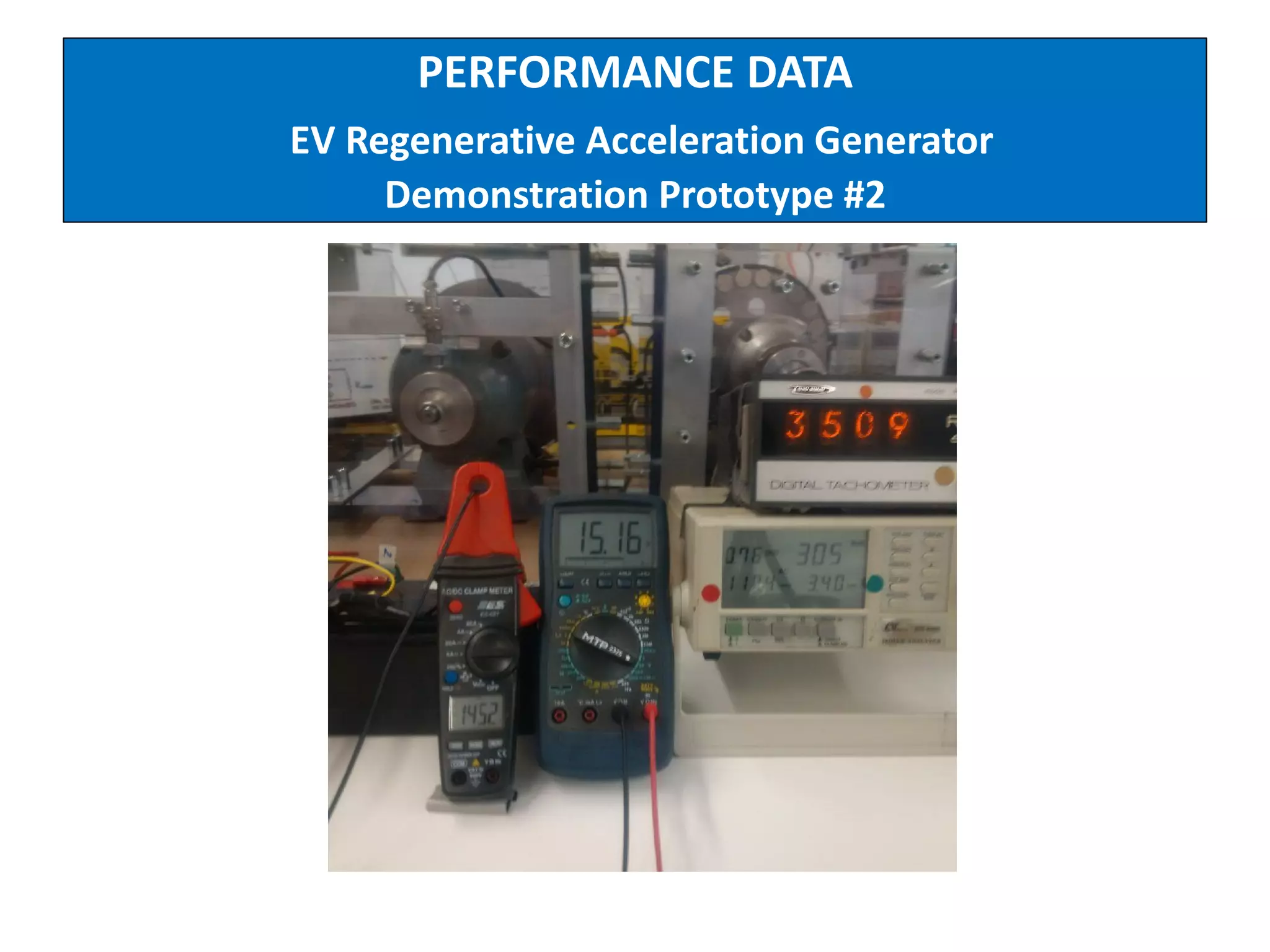
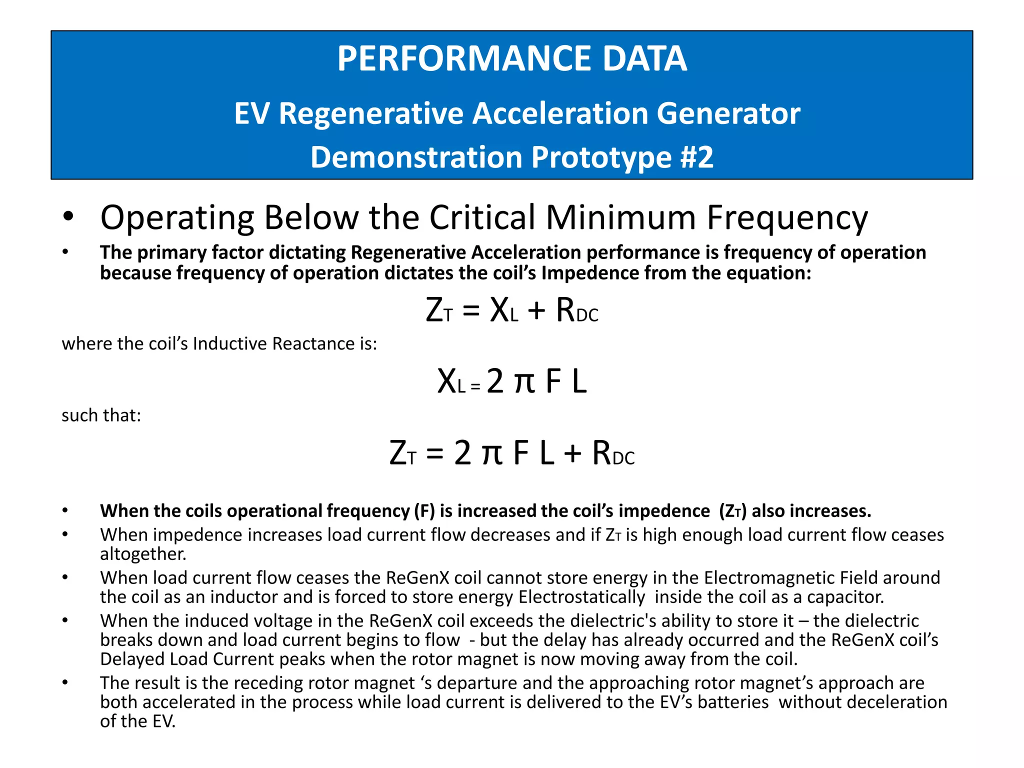
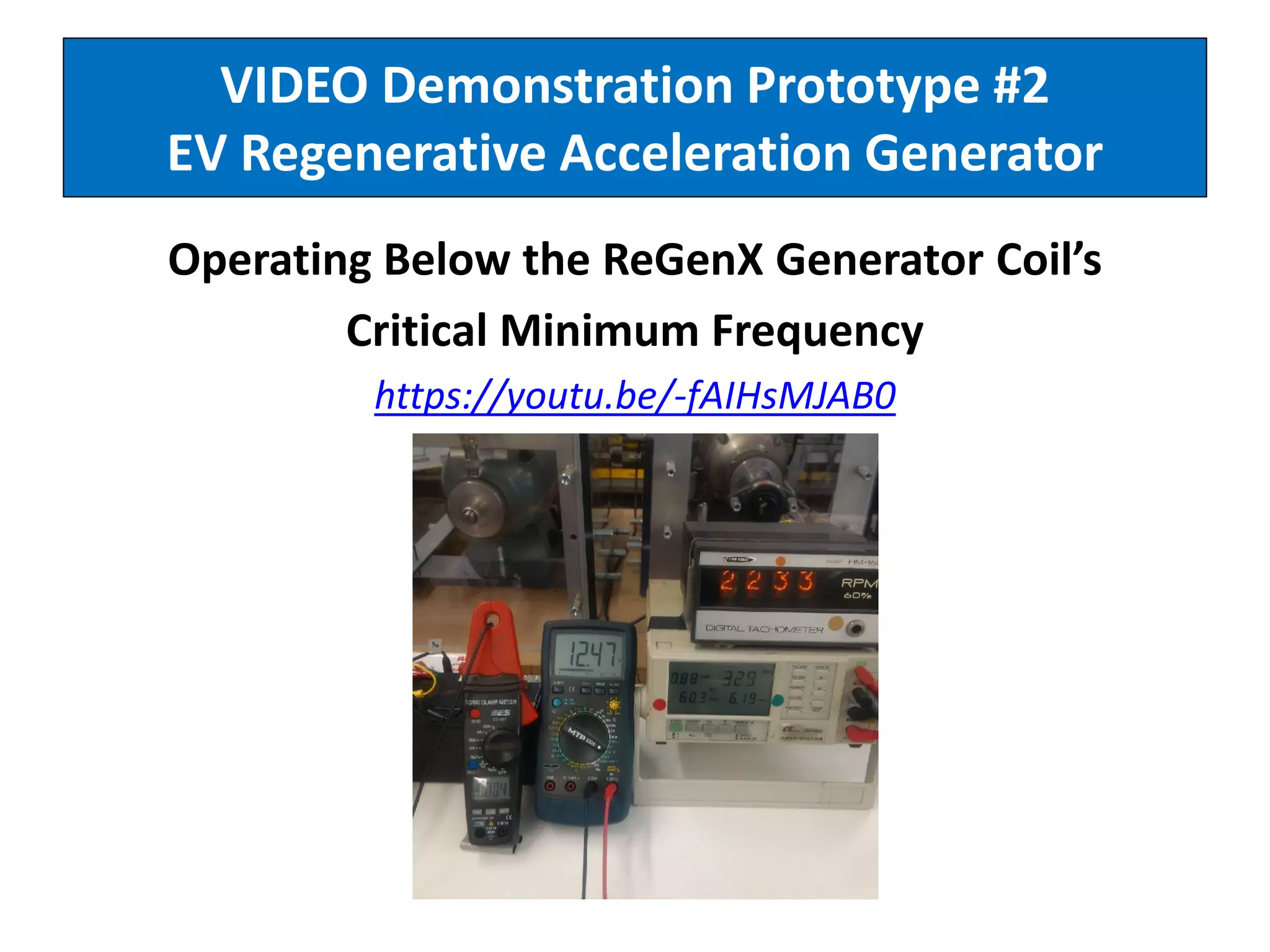
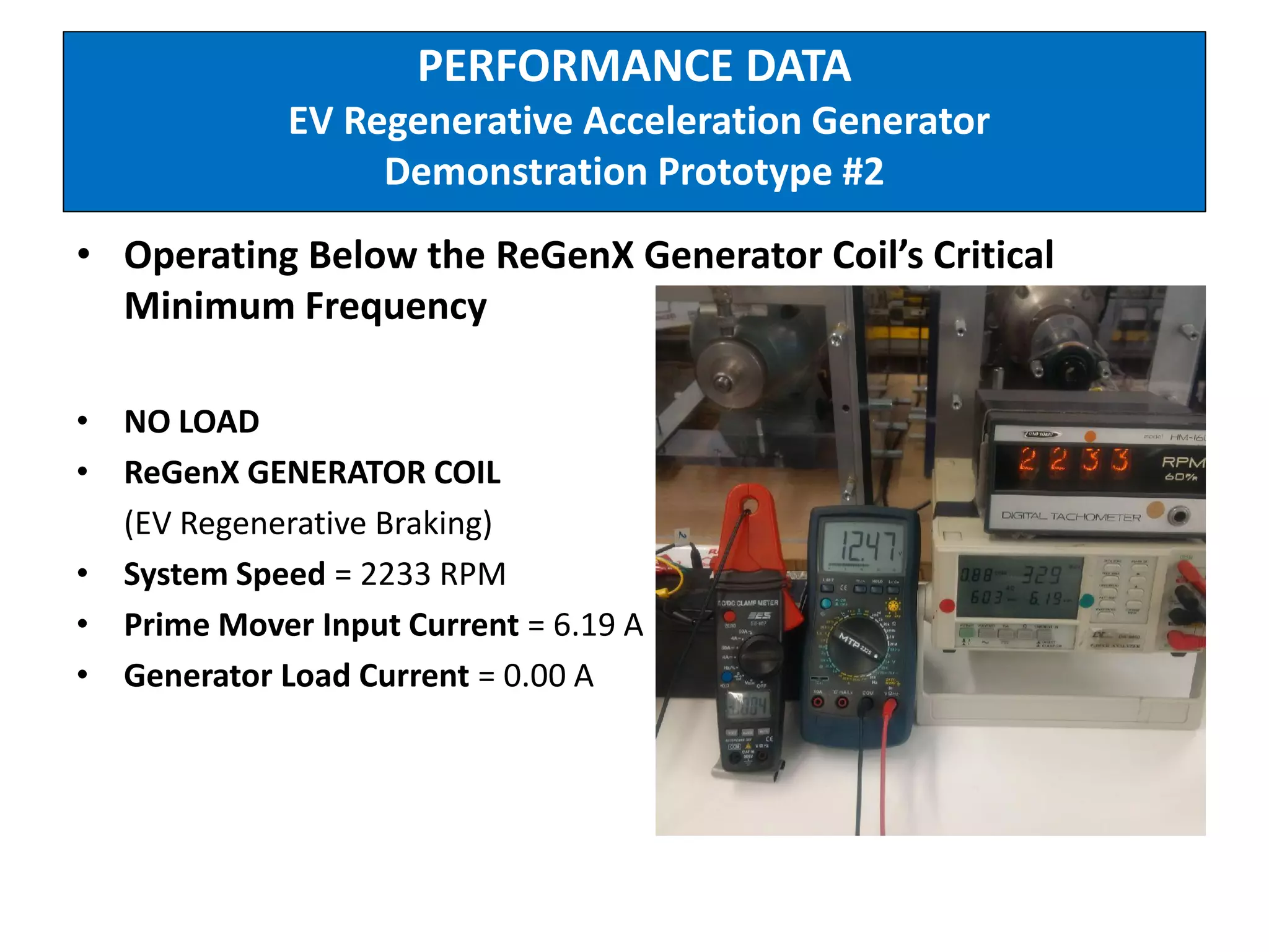
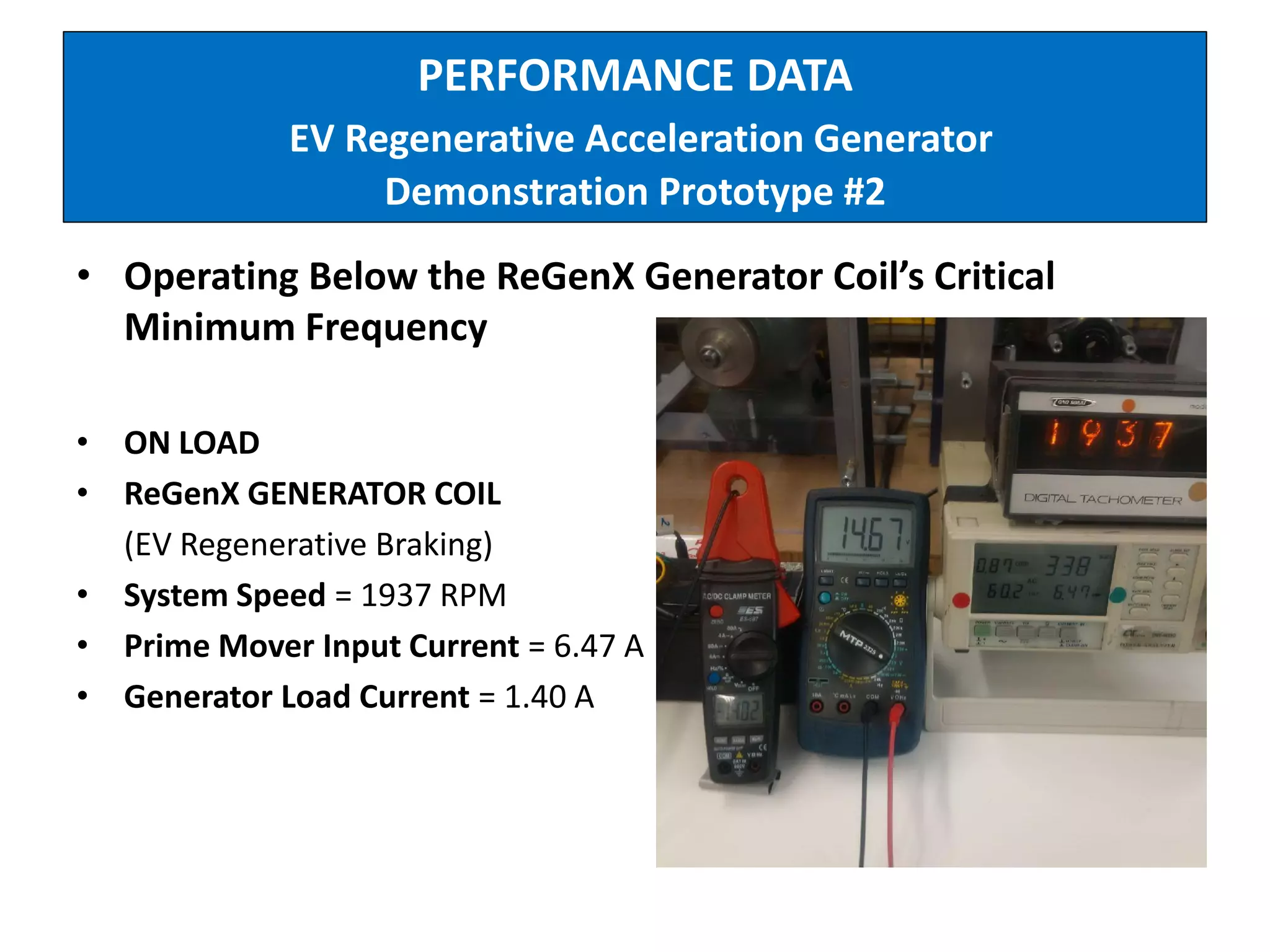
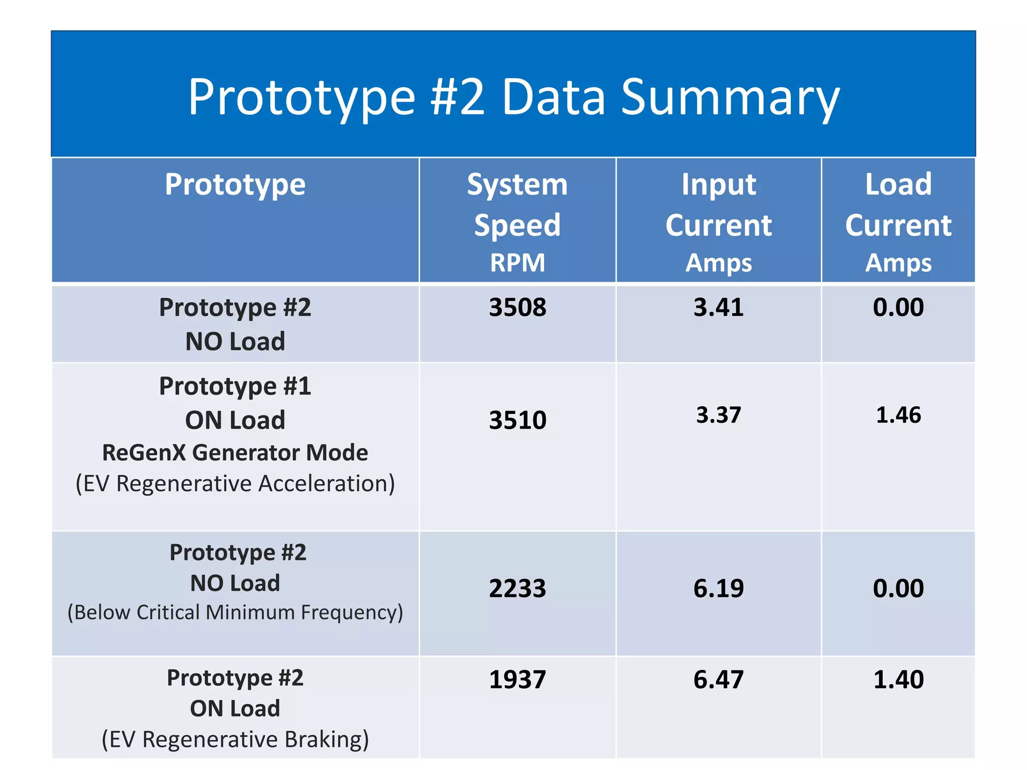
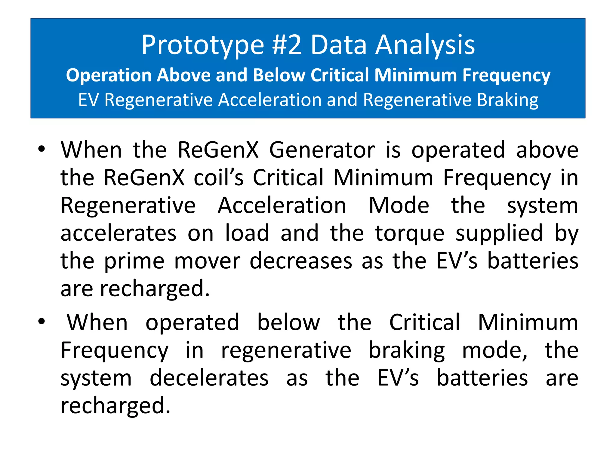
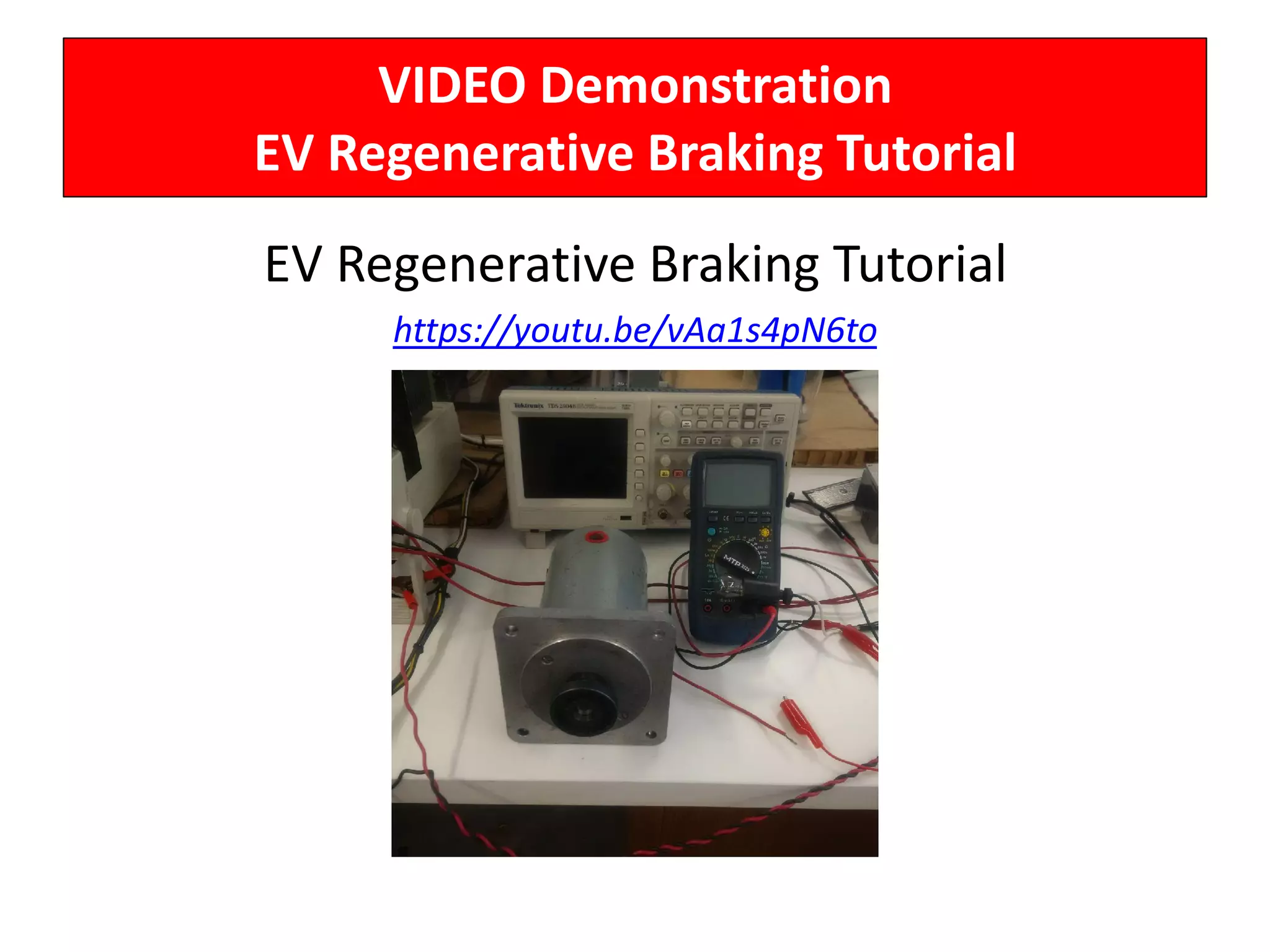
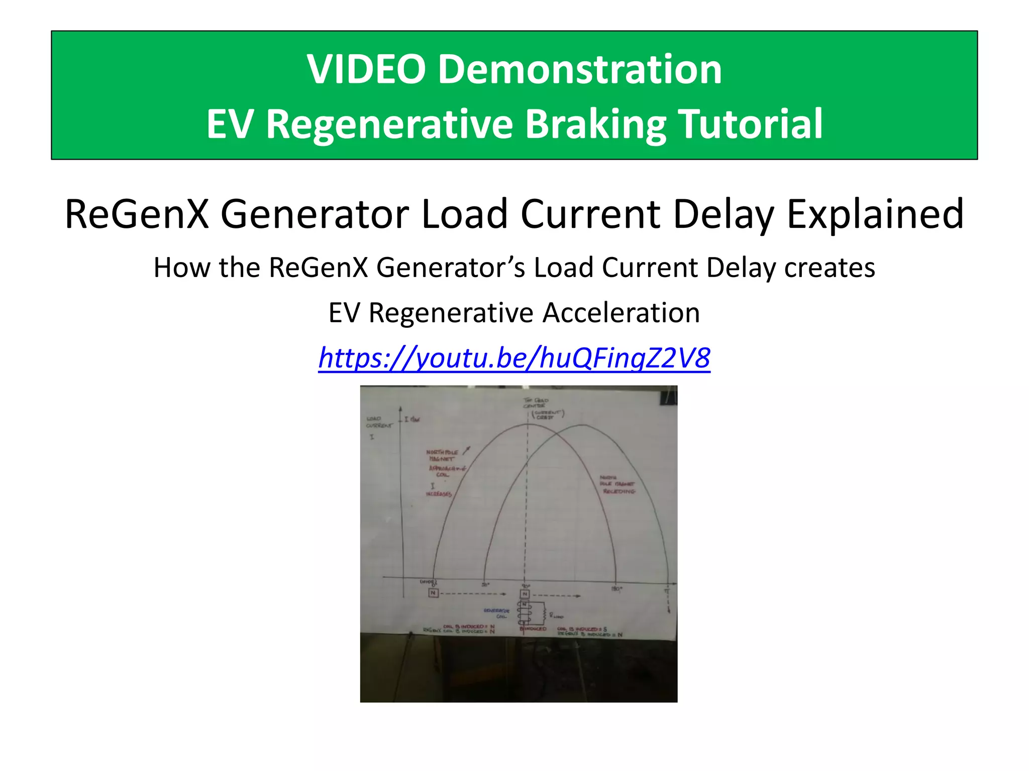
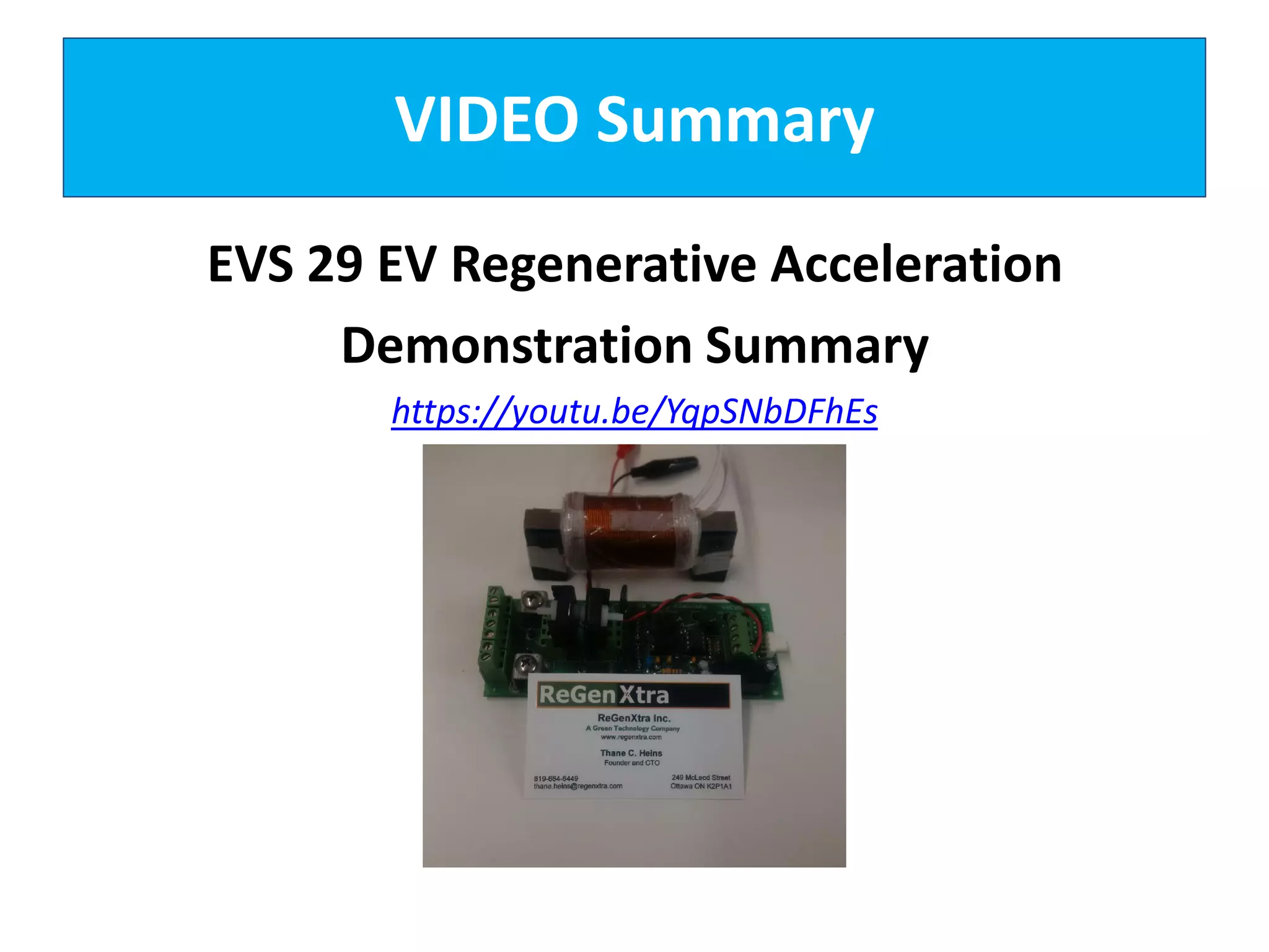

The document describes demonstrations of two prototypes for an electric vehicle regenerative acceleration system. Prototype 1 shows how the regenerative acceleration generator coil produces a delayed load current compared to a conventional coil, assisting the departure of rotor magnets. Performance data shows it recharges batteries while maintaining vehicle speed. Prototype 2 demonstrates regenerative acceleration above a critical frequency and regenerative braking below it through load current manipulation. It recharges batteries without decelerating above the critical frequency.


