
Recommended
Recommended
More Related Content
What's hot
What's hot (20)
Similar to AVL ReGenX Generator Prototypes for Testing and Performance Validation.pdf
Similar to AVL ReGenX Generator Prototypes for Testing and Performance Validation.pdf (20)
More from Thane Heins
More from Thane Heins (20)
Recently uploaded
Recently uploaded (20)
AVL ReGenX Generator Prototypes for Testing and Performance Validation.pdf
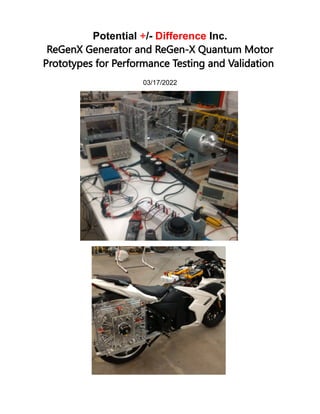
- 1. Potential +/- Difference Inc. ReGenX Generator and ReGen-X Quantum Motor Prototypes for Performance Testing and Validation 03/17/2022
- 2. ReGenX Generator Prototype #1 ReGenX Prototype #1 is a demonstration prototype who's primary function is to introduce the ReGenX Generator's US patented Load Current Delay feature which is the primary contributing factor to the generator's ability to reverse Generator Armature Reaction (aka EV regenerative braking) and to produce EV Regenerative Acceleration. Prototype #1 consists of an E Core Salient Pole generator coil which incorporates 2 different coil types. The outer winding of the ReGenX E Coil is the Conventional Generator Coil and the inner winding is the ReGenX Generator Coil. The Conventional Generator Coil delivers Electrical Power to the Load and it produces Counter-Electromagnetic- Torque while the ReGenX Generator Coils provide the Complementary-Electromagnetic-Torque in order to counteract the counter-torque produced by the Conventional Coil. Prototype #1 is also designed to demonstrate that the ReGenX Generator Coil(s) have the ability to deliver more Electrical Output Power to the Load over the Conventional Generator Coil without requiring additional Prime Mover Input Power and without additional Mechanical Drive Shaft Input Power over the No- Load Steady State Speed / Rotational Equilibrium requirement. Prototype #1 and E Core ReGenX Generator Coil
- 3. ReGenX Prototype #1 Dimensions and Components Prime Mover Type: 1/3 Hp Induction Motor Prime Mover Voltage = 120 Volts Prime Mover Current = 1.5 Amps Rotor: Permanent Magnet Rotor Rotor Masses Prime Mover Rotor + PM Rotor = 3.2 kg Rotor Radius = 0.1524 M Rated Speed = 3500 RPM Drive Shaft Height = 8 inches (approx) Drive Shaft Diameter = 0.5 inch Coil & Core Design: Salient Pole E Core with single Conventional Generator Coil and dual ReGenX Generator Coils on the same E Core. Loads: 10 Ohm AC Light Bulbs with Power Factor of 1 Generator Output = 10 Watts AC (10 Volts, 1.0 Amps) Desired Testing Procedure: 1. Bring system up to Rotational Equilibrium on No-Load and record Prime Mover Input Power Consumption, Drive Shaft Torque and Speed 2. Place Conventional Generator Coil On-Load and record Prime Mover Input Power Consumption INCREASE, Drive Shaft Torque INCREASE and Speed DECREASE. 3. Place ReGenX Generator Coil On-Load and record Prime Mover Input Power Consumption DECREASE, Drive Shaft Torque INCREASE and Speed INCREASE. Observational Expectations: Conventional Generator Performance 1) When the Conventional Generator Coil is placed On-Load the System Speed will DECREASE to BELOW that established at Rotational Equilibrium at idle because the Electromagnetic Fields created around the Conventional Generator Coil produces a Counter-Electromagnetic-Torque and it decelerates/reduces the Kinetic Energy of the generator/prime mover system. 1a) The Kinetic Energy of the system is DECREASED. 2) About 10 Watts AC will be delivered to the Load. 3) The induction motor/prime mover Input Power Consumption will INCREASE automatically or will need to be INCREASED manually in order to maintain the original No-Load System Speed at Rotational Equilibrium. 4) And the Drive Shaft Mechanical Power will need to be INCREASED ABOVE 10 Watts (above the Electrical Power delivered to the load). 5) The Conventional Generator Coil's Load Current Sine Wave can be observed on the Oscilloscope.
- 4. ReGenX Generator Performance 6) When the ReGenX Generator Coil is placed On-Load the System Speed will INCREASE to ABOVE that established at Rotational Equilibrium at idle because the Electromagnetic Field created around the ReGenX Generator Coil produces a Complementary-Electromagnetic-Torque and it accelerates/increases the Kinetic Energy of the generator/prime mover system. 6b) The Kinetic Energy of the system will be INCREASED. 7) About 11 Watts AC will be delivered to the Load. 8) The induction motor/prime mover Input Power Consumption will DECREASE automatically or will need to be DECREASED manually in order to maintain the original No-Load System Speed at Rotational Equilibrium. 9) And the Drive Shaft Mechanical Power will need to be DECREASED to BELOW that which was established at Rotational Equilibrium at idle on No-Load. 10) The ReGenX Generator Coil's Load Current Sine Wave can be observed on the Oscilloscope with about a 50 Degree Load Current Time Delay. SPECIAL NOTE: Electromagnetic Field Energy Flux Harvesting 11) When the ReGenX Generator Coil is placed On-Load it will be mathematically observed that the Output Power delivered to the Load from the Conventional Generator Coil will increase instantaneously before the System Speed has had a chance to increase, i.e. before the Rate Change of Magnetic Flux in the coil increases with increased frequency. Note: Prototype #1 employs: 1) a Conventional Generator Coil to provide Electrical Power to the load 2) and the ReGenX Generator Coils to provide a Complementary-Electromagnetic-Torque to the system in order to override the Conventional Generator Coil's Counter-Electromagnetic-Torque. 14) This means that the Electromagnetic Field created around the ReGenX Generator Coil(s) (which are wound on the Middle Core Finger of the E Core is being collected into the Core of the Conventional Generator Coil which is wound on the Outer Core Fingers of the E Core. 15) The ReGenX Generator Coils' Electromagnetic Field's perform TWO different forms of Work; 1) Electro-Mechanical: Accelerating or performing Positive Work on the generator's Rotating Magnetic Field and 2) Electrical: Increasing the Magnitude of the Magnetic Flux (Rotor Flux + Electromagnetic Flux) inside the Conventional Generator Coil and thereby increasing the generator's output power delivered to the load.
- 5. 16) Load Current Sine Waves for Conventional Generator Coil and ReGenX Generator Coil in Prototype #1 measured across identical Purely Resistive Loads. Detailed Description of Time Delayed Bfield Production in the ReGenX E Coil How Two Types of Work is Performed in Prototype #1 Negative Electro-Mechanical Work Performed by a Conventional Generator Coil According to Lenz's Law of Induction, when a North Pole Magnet approaches a generator coil and current flows in the coil a North Pole Electromagnetic Field will be created around the coil which will RESIST the magnet's approach. And when the North Pole Magnet moves away from the coil a South Pole Electromagnetic Field will be created which will RESIST the magnet's departure away from the coil. Rotor Flux Direction and Induced Bfield Electromagnetic Flux in the ReGenX E Coil
- 6. THE ReGenX E COIL IS DESIGNED SO THAT THE COMPLEMENTARY-ELECTROMAGNETIC- TORQUE MAGNITUDE PRODUCED BY THE ReGenX GENERATOR COIL IS GREATER IN MAGNITUDE THAN THE COUNTER-ELECTROMAGNETIC-TORQUE MAGNITUDE PRODUCED BY THE CONVENTIONAL GENERATOR COIL SO THAT THE NET EFFECT IS SYSTEM ACCELERATION AND KINETIC ENERGY INCREASE. Positive Electromagnetic Field Energy Harvesting FLUX HARVESTING How ReGenX Coil Flux Harvesting Occurs in the Conventional Generator Coil According to Lenz's Law of Induction the Conventional Generator Coil will be creating a South Pole RESISTING Electromagnetic Field when the North Pole Magnet is moving away from it. The ReGenX Generator coil is creating a South Pole Electromagnetic Field while the Conventional Coil's Core Flux Direction as also a South Pole direction and the two IDENTICAL FLUXES SUM together and increase the Conventional Generator Coil's Electric power delivered to the load. While AT THE SAME TIME the ReGenX Coil is ALSO producing South Pole Electromagnetic Field Energy which performs Positive Work ACCELERATING the South Pole Rotor Magnet's departure away from the ReGenX Coil, while simultaneously ATTRACTING the North Pole Rotor Magnet which is approaching the ReGenX Generator Coil. Prototype #1 Schematic Diagram
- 7. PROTOTYPE #1 What is Generator Armature Reaction (EV Regenerative Braking) and EV Regenerative Acceleration: VIDEO DEMONSTRATION: https://youtu.be/pyO8FUTDX68
- 8. ReGenX Generator and ReGen-X Quantum Motor Prototype #2 ReGenX Generator Prototype #2 consists of 1 Conventional Generator Coil (yellow) and 3 ReGenX Generator Coils (green, red and blue). Prototype #2 consists of 4 C Core Salient Pole generator coils. 3.5 Amp Commercially manufactured C Core ReGenX Coil 60 Amp ReGenX Generator Coil ReGenX Prototype #2 Dimensions and Components Prime Mover Type: 1 Hp Induction Motor Prime Mover Voltage = 120 Volts Prime Mover Current = 5 Amps Rotor: Permanent Magnet Rotor Rotor Masses Prime Mover Rotor + PM Rotor = 5.7 Kg Rotor Radius = 0.31 M Drive Shaft Height = 8 inches (approx) Drive Shaft Diameter = 0.75 inch Rated Speed = 3500 RPM Coil & Core Design: Salient Pole C Core with Conventional Generator Coil and 3 ReGenX Generator Coils Loads: 12 Volt Battery Generator Output = 90 Watts DC (10 Volts, 1.0 Amps)
- 9. Desired Testing Procedure: 4. Bring system up to Rotational Equilibrium on No-Load and record Prime Mover Input Power Consumption, Drive Shaft Torque and Speed 5. Place Conventional Generator Coil On-Load and record Prime Mover Input Power Consumption INCREASE, Drive Shaft Torque INCREASE and Speed DECREASE. 6. Place ReGenX Generator Coils On-Load and record Prime Mover Input Power Consumption DECREASE, Drive Shaft Torque INCREASE and Speed INCREASE. Observational Expectations: Conventional Generator Performance 17) When the Conventional Generator Coil is placed On-Load the System Speed will DECREASE to BELOW that established at Rotational Equilibrium at idle because the Electromagnetic Fields created around the Conventional Generator Coil produces a Counter-Electromagnetic-Torque and it decelerates/reduces the Kinetic Energy of the generator/prime mover system. 17a) The Kinetic Energy of the system will DECREASE. 18) About 60 Watts AC will be delivered to the Load. 19) The induction motor/prime mover Input Power Consumption will INCREASE or will need to be INCREASED manually in order to maintain the original No-Load System Speed at Rotational Equilibrium. 20) And the Drive Shaft Mechanical Power will need to be INCREASED ABOVE 60 Watts (above the Electrical Power delivered to the load).
- 10. ReGenX Generator Performance 21) When the ReGenX Generator Coil is placed On-Load the System Speed will INCREASE to ABOVE that established at Rotational Equilibrium at idle. 21a) The Kinetic Energy of the system will be INCREASED. 22) About 90 Watts DC will be delivered to the Load. 23) The induction motor/prime mover Input Power Consumption will DECREASE or will need to be DECREASED manually in order to maintain the original No-Load System Speed at Rotational Equilibrium. 24) And the Drive Shaft Mechanical Power will need to be DECREASED to BELOW that which was established at Rotational Equilibrium at idle on No-Load. 25) Table 1.0 demonstrates that ReGenX Prototype #1 delivers 90.2 Watts to the load while the Kinetic Energy of the generator/prime mover system increases by 70 Joules. 26) NO additional Input Energy is supplied to the Prime Mover and NO additional Mechanical Drive Shaft Power is supplied to the ReGenX Generator. 27) The ReGenX Generator coils deliver 90.2 Watts of Electrical Output Power to the load. 28) The Kinetic Energy of the system is increased by 70 Joules.
- 11. PROTOTYPE #2 ReGen-X EV Quantum Motor Introduction: https://youtu.be/Oj4flCoVdXs
- 12. ReGen-X Quantum Motor Performance 29) When the ReGen-X Quantum Motor is placed On-Load the System Speed and Drive Shaft Torque will INCREASE to ABOVE that magnitude which was established at Rotational Equilibrium at idle. 30) NO additional Input Energy is supplied to the Prime Mover and or the ReGen-X Quantum Motor coils and NO additional Mechanical Drive Shaft Power is supplied to the ReGen-X Quantum Motor. 31) The Kinetic Energy of the system will be INCREASED by 153 Joules.
- 13. ReGenX Generator Performance when Operated Below the Coil's Critical Minimum Frequency 32) When the ReGenX Generator Coil is operated below the coil's Critical Minimum Frequency and when it is placed On-Load the System Speed will DECREASE to BELOW that established at Rotational Equilibrium at idle. 32a) The Kinetic Energy of the system will be DECREASED. 33) 0.00 Watts DC will be delivered to the Load and the system will stall. ReGenX EV Regenerative Acceleration Generator Prototype #3
- 14. ELECTRIC VEHICLE REGENERATIVE ACCELERATION INNOVATION INTRODUCTION VIDEO: https://youtu.be/3O-uFXiObBc Potential +/- Difference Inc. "We generate solutions"