SlideShare a Scribd company logo
1 of 4
Download to read offline
STRENGTH CALCULATION FOR SLOTTED FLANGE WITH SWING BOLT
Bolt Diameter 5/8 Inch Bolt Size Db = mm
Pin Diameter Dp = mm
Top Bracket Length dT = mm
Top Bracket Width bT = mm
Bottom Bracket Length dB = mm
Bottom Bracket Thickness bB = mm
Pin Hole At Bottom Bracket Dh = mm
Yield Strength of Bracket  SA240 Gr 304 Fy(br) = N/mm2
Yield Strength of Weld SA240 Gr 304 Fy(w) = N/mm2
Yield strength of Bolt SA240 Gr 304 Fy(b) = N/mm2
Yield strength of Pin SA240 Gr 304 Fy(p) = N/mm2
Allowable Bending Stress of Bracket, x Fy(br) Fba(br) = N/mm2
Allowable Shear Stress of Bracket, x Fy(br) Fva(br) = N/mm2
Allowable Tensile Stress of Bolt,  x Fy(b) Fta(b) = N/mm2
Allowable Shear Stress of Weld, x Fy(w) Fva(w) = N/mm2
Allowable Bending Stress of Pin, x Fy(p) Fba(p) = N/mm2
Allowable Shear Stress of Pin,  x Fy(p) Fva(p) = N/mm2
153.75
102.5
21
34
8
14
123
12.881
12.7
205
205
205
102.5
153.75
205
22
102.50.5
0.75
0.5
0.6
0.5
0.75
Top Bracket cross section 
dimension is 22 x 21 for 
each side
14
A) Shear Stress For Weld Attachment of Bracket/Shell
Total Operating Bolt Load, WM1 (Read from PV Elite) WM1 = N
Total Number of Bracket & Bolts N(b) =
Operating Bolt Load Per Bracket & Bolt, F(b)=WM1/N(b) F(b) = N
Top Bracket
Total Weld Length Per Set of Bracket L(wtbr) = mm
Fillet Weld Leg Size of Bracket F(wtbr) = mm
Weld Shear Area, A(wtbr)=L(wtbr) xF(wtbr) A(wtbr) = mm2
Shear Stress (Max), Sv(wtbr)=F(b)/A(wtbr) OK Sv(wtbr) = N/mm2
Bottom Bracket
Total Weld Length Per Set of Bracket L(wbbr) = mm
Fillet Weld Leg Size of Bracket F(wbbr) = mm
Weld Shear Area, A(wbbr)=L(wbbr) xF(wbbr) A(wbbr) = mm2
Shear Stress (Max), Sv(wbbr)=F(b)/A(wbbr) OK Sv(wbbr) = N/mm2
B) Bending Stress & Moment For Brackets (Per Set)
Moment Arm For Bracket At Full Bolt Load  L(m) = mm
Top Bracket
Neutral Axis For The Set of Bracket y(tbr) = mm
2nd Moment of Area per Set of Bracket, I(tbr)=(bd3
)/12   I(tbr) = mm4
Bending Moment (Max), M(tbr)=F(b) x L(m) M(tbr) = N‐mm
Bending Stress (Max), Sb(tbr)=M(tbr)/[I(tbr)/y(tbr)] OK Sb(tbr) = N/mm2
Bottom Bracket
Neutral Axis For The Set of Bracket y(bbr) = mm
2nd Moment of Area per Set of Bracket, I(bbr)=(bd
3
)/12   I(bbr) = mm4
Bending Moment (Max), M(bbr)=F(b) x L(m) M(bbr) = N‐mm
Bending Stress (Max), Sb(bbr)=M(bbr)/[I(bbr)/y(bbr)] OK Sb(bbr) = N/mm2
C) Shear Stress For The Bottom Bracket Due To Load At Point of Pin Contact
Operating Bolt Load Per Bracket & Bolt, F(b)=WM1/N(b) F(b) = N
Top Bracket
Shear Area For The Bracket,  A(tbr) = mm2
Shear Stress (Max), Sv(tbr)=F(b)/A(tbr) OK Sv(tbr) = N/mm2
Bottom Bracket
Shear Area For The Bracket,  A(bbr) = mm2
Shear Stress (Max), Sv(bbr)=F(b)/A(bbr) OK Sv(bbr) = N/mm2
924
7.85
136
2
272
26.67
10
10666.67
108830.83
102.03
29021.555
4
7255.39
0
0
0
32.12
544
7255.39
13.34
0.00
15
108830.83
37268.00
11
D) Bending Moment, Bending Stress & Shear Stress For Pin Insert Through Bottom Bracket
F1 = F2 =
y= mm
R1 = R2 =
Max Bending Moment, M(p) = F x L M(p) = N‐mm
Neutral Axis For The Pin y = mm
2nd Moment of Area, I(p)=πd
4
 /64 I(p) = mm4
Max Bending Stress, Sb(p) = M/(I/y) OK Sb(p) = N/mm2
Shear Stress At Point Of Contact Between Pin And Bracket
Cross section Area of Pin A(p) = mm2
Shear Stress (Max), Sv(p)=F(R1)/[SF x A(p)] SF=  0.5 OK Sv(p) = N/mm2
E) Axial Tension Of Bolt
Root Area of Bolt A(b) = mm2
Shear Stress (Max), St(b)=F(b)/A(b) OK St(b) = N/mm2
F) Load Combination
Top Bracket OK LC(tbr) =
Bottom Bracket OK LC(bbr) =
Pin OK LC(p) = 0.882
55.68
0.794
46.17
6.35
59.66
2.560 2.560
Bracket(bot) Width
0.286
130.313
3627.69 3627.69
1276.98
3627.69 3627.69
6.35
121.610
9285.08
18
14

More Related Content

What's hot

Machine tools lecture notes iii-i
Machine tools lecture notes iii-iMachine tools lecture notes iii-i
Machine tools lecture notes iii-iBanothTarajiNaik
 
Welding defects
Welding defectsWelding defects
Welding defectsHung Le
 
09038_Flud_ASME Sec IX_WPQ
09038_Flud_ASME Sec IX_WPQ09038_Flud_ASME Sec IX_WPQ
09038_Flud_ASME Sec IX_WPQmathew flud
 
Lecture 8 drilling machine
Lecture 8 drilling machineLecture 8 drilling machine
Lecture 8 drilling machineRania Atia
 
Geit 10017 en-weldinspection rt interpretation-22-25
Geit 10017 en-weldinspection rt interpretation-22-25Geit 10017 en-weldinspection rt interpretation-22-25
Geit 10017 en-weldinspection rt interpretation-22-25Balkishan Dyavanapelly
 
Weld design symbols
Weld design symbolsWeld design symbols
Weld design symbolsRavi Shankar
 
Nbr 8855 eb 168 propriedades mecanicas de elementos de fixacao parafusos e pr...
Nbr 8855 eb 168 propriedades mecanicas de elementos de fixacao parafusos e pr...Nbr 8855 eb 168 propriedades mecanicas de elementos de fixacao parafusos e pr...
Nbr 8855 eb 168 propriedades mecanicas de elementos de fixacao parafusos e pr...ejfelix
 
Chapt introduction to_jigs_and fixtures
Chapt introduction to_jigs_and fixturesChapt introduction to_jigs_and fixtures
Chapt introduction to_jigs_and fixturesDushyant Vyas
 
Joining,cutting,surface treatment process
Joining,cutting,surface treatment processJoining,cutting,surface treatment process
Joining,cutting,surface treatment processTariq Jamshaid
 
Power Piping ASME Guide.PDF
Power Piping ASME Guide.PDFPower Piping ASME Guide.PDF
Power Piping ASME Guide.PDFTeddy Setiady
 
Chapter 08
Chapter 08Chapter 08
Chapter 08mcfalltj
 
ASME BOILER & PRESSURE SECTION VIII.ppt
ASME BOILER & PRESSURE SECTION VIII.pptASME BOILER & PRESSURE SECTION VIII.ppt
ASME BOILER & PRESSURE SECTION VIII.ppthesham ismail
 
ASTM-E446-standard reference radiographs for steel castings up to 2 in. (50.8...
ASTM-E446-standard reference radiographs for steel castings up to 2 in. (50.8...ASTM-E446-standard reference radiographs for steel castings up to 2 in. (50.8...
ASTM-E446-standard reference radiographs for steel castings up to 2 in. (50.8...Gulfnde Industrial Services
 

What's hot (20)

Thread fastener
Thread fastenerThread fastener
Thread fastener
 
Shaft couplings1
Shaft couplings1Shaft couplings1
Shaft couplings1
 
Machine tools lecture notes iii-i
Machine tools lecture notes iii-iMachine tools lecture notes iii-i
Machine tools lecture notes iii-i
 
Gaskets.pptx
Gaskets.pptxGaskets.pptx
Gaskets.pptx
 
Casting
CastingCasting
Casting
 
Welding defects
Welding defectsWelding defects
Welding defects
 
09038_Flud_ASME Sec IX_WPQ
09038_Flud_ASME Sec IX_WPQ09038_Flud_ASME Sec IX_WPQ
09038_Flud_ASME Sec IX_WPQ
 
Lecture 8 drilling machine
Lecture 8 drilling machineLecture 8 drilling machine
Lecture 8 drilling machine
 
Geit 10017 en-weldinspection rt interpretation-22-25
Geit 10017 en-weldinspection rt interpretation-22-25Geit 10017 en-weldinspection rt interpretation-22-25
Geit 10017 en-weldinspection rt interpretation-22-25
 
Weld design symbols
Weld design symbolsWeld design symbols
Weld design symbols
 
Nbr 8855 eb 168 propriedades mecanicas de elementos de fixacao parafusos e pr...
Nbr 8855 eb 168 propriedades mecanicas de elementos de fixacao parafusos e pr...Nbr 8855 eb 168 propriedades mecanicas de elementos de fixacao parafusos e pr...
Nbr 8855 eb 168 propriedades mecanicas de elementos de fixacao parafusos e pr...
 
Chapt introduction to_jigs_and fixtures
Chapt introduction to_jigs_and fixturesChapt introduction to_jigs_and fixtures
Chapt introduction to_jigs_and fixtures
 
Jigs & fixtures
Jigs & fixturesJigs & fixtures
Jigs & fixtures
 
Fasteners
FastenersFasteners
Fasteners
 
Joining,cutting,surface treatment process
Joining,cutting,surface treatment processJoining,cutting,surface treatment process
Joining,cutting,surface treatment process
 
Power Piping ASME Guide.PDF
Power Piping ASME Guide.PDFPower Piping ASME Guide.PDF
Power Piping ASME Guide.PDF
 
CSWIP Intro
CSWIP IntroCSWIP Intro
CSWIP Intro
 
Chapter 08
Chapter 08Chapter 08
Chapter 08
 
ASME BOILER & PRESSURE SECTION VIII.ppt
ASME BOILER & PRESSURE SECTION VIII.pptASME BOILER & PRESSURE SECTION VIII.ppt
ASME BOILER & PRESSURE SECTION VIII.ppt
 
ASTM-E446-standard reference radiographs for steel castings up to 2 in. (50.8...
ASTM-E446-standard reference radiographs for steel castings up to 2 in. (50.8...ASTM-E446-standard reference radiographs for steel castings up to 2 in. (50.8...
ASTM-E446-standard reference radiographs for steel castings up to 2 in. (50.8...
 

Recently uploaded

Max. shear stress theory-Maximum Shear Stress Theory ​ Maximum Distortional ...
Max. shear stress theory-Maximum Shear Stress Theory ​  Maximum Distortional ...Max. shear stress theory-Maximum Shear Stress Theory ​  Maximum Distortional ...
Max. shear stress theory-Maximum Shear Stress Theory ​ Maximum Distortional ...ronahami
 
Circuit Breakers for Engineering Students
Circuit Breakers for Engineering StudentsCircuit Breakers for Engineering Students
Circuit Breakers for Engineering Studentskannan348865
 
Working Principle of Echo Sounder and Doppler Effect.pdf
Working Principle of Echo Sounder and Doppler Effect.pdfWorking Principle of Echo Sounder and Doppler Effect.pdf
Working Principle of Echo Sounder and Doppler Effect.pdfSkNahidulIslamShrabo
 
DBMS-Report on Student management system.pptx
DBMS-Report on Student management system.pptxDBMS-Report on Student management system.pptx
DBMS-Report on Student management system.pptxrajjais1221
 
Path loss model, OKUMURA Model, Hata Model
Path loss model, OKUMURA Model, Hata ModelPath loss model, OKUMURA Model, Hata Model
Path loss model, OKUMURA Model, Hata ModelDrAjayKumarYadav4
 
Introduction-to- Metrology and Quality.pptx
Introduction-to- Metrology and Quality.pptxIntroduction-to- Metrology and Quality.pptx
Introduction-to- Metrology and Quality.pptxProfASKolap
 
Involute of a circle,Square, pentagon,HexagonInvolute_Engineering Drawing.pdf
Involute of a circle,Square, pentagon,HexagonInvolute_Engineering Drawing.pdfInvolute of a circle,Square, pentagon,HexagonInvolute_Engineering Drawing.pdf
Involute of a circle,Square, pentagon,HexagonInvolute_Engineering Drawing.pdfJNTUA
 
litvinenko_Henry_Intrusion_Hong-Kong_2024.pdf
litvinenko_Henry_Intrusion_Hong-Kong_2024.pdflitvinenko_Henry_Intrusion_Hong-Kong_2024.pdf
litvinenko_Henry_Intrusion_Hong-Kong_2024.pdfAlexander Litvinenko
 
Adsorption (mass transfer operations 2) ppt
Adsorption (mass transfer operations 2) pptAdsorption (mass transfer operations 2) ppt
Adsorption (mass transfer operations 2) pptjigup7320
 
21P35A0312 Internship eccccccReport.docx
21P35A0312 Internship eccccccReport.docx21P35A0312 Internship eccccccReport.docx
21P35A0312 Internship eccccccReport.docxrahulmanepalli02
 
一比一原版(Griffith毕业证书)格里菲斯大学毕业证成绩单学位证书
一比一原版(Griffith毕业证书)格里菲斯大学毕业证成绩单学位证书一比一原版(Griffith毕业证书)格里菲斯大学毕业证成绩单学位证书
一比一原版(Griffith毕业证书)格里菲斯大学毕业证成绩单学位证书c3384a92eb32
 
Passive Air Cooling System and Solar Water Heater.ppt
Passive Air Cooling System and Solar Water Heater.pptPassive Air Cooling System and Solar Water Heater.ppt
Passive Air Cooling System and Solar Water Heater.pptamrabdallah9
 
UNIT 4 PTRP final Convergence in probability.pptx
UNIT 4 PTRP final Convergence in probability.pptxUNIT 4 PTRP final Convergence in probability.pptx
UNIT 4 PTRP final Convergence in probability.pptxkalpana413121
 
Independent Solar-Powered Electric Vehicle Charging Station
Independent Solar-Powered Electric Vehicle Charging StationIndependent Solar-Powered Electric Vehicle Charging Station
Independent Solar-Powered Electric Vehicle Charging Stationsiddharthteach18
 
5G and 6G refer to generations of mobile network technology, each representin...
5G and 6G refer to generations of mobile network technology, each representin...5G and 6G refer to generations of mobile network technology, each representin...
5G and 6G refer to generations of mobile network technology, each representin...archanaece3
 
Raashid final report on Embedded Systems
Raashid final report on Embedded SystemsRaashid final report on Embedded Systems
Raashid final report on Embedded SystemsRaashidFaiyazSheikh
 
Presentation on Slab, Beam, Column, and Foundation/Footing
Presentation on Slab,  Beam, Column, and Foundation/FootingPresentation on Slab,  Beam, Column, and Foundation/Footing
Presentation on Slab, Beam, Column, and Foundation/FootingEr. Suman Jyoti
 
CLOUD COMPUTING SERVICES - Cloud Reference Modal
CLOUD COMPUTING SERVICES - Cloud Reference ModalCLOUD COMPUTING SERVICES - Cloud Reference Modal
CLOUD COMPUTING SERVICES - Cloud Reference ModalSwarnaSLcse
 
Databricks Generative AI Fundamentals .pdf
Databricks Generative AI Fundamentals  .pdfDatabricks Generative AI Fundamentals  .pdf
Databricks Generative AI Fundamentals .pdfVinayVadlagattu
 
Seismic Hazard Assessment Software in Python by Prof. Dr. Costas Sachpazis
Seismic Hazard Assessment Software in Python by Prof. Dr. Costas SachpazisSeismic Hazard Assessment Software in Python by Prof. Dr. Costas Sachpazis
Seismic Hazard Assessment Software in Python by Prof. Dr. Costas SachpazisDr.Costas Sachpazis
 

Recently uploaded (20)

Max. shear stress theory-Maximum Shear Stress Theory ​ Maximum Distortional ...
Max. shear stress theory-Maximum Shear Stress Theory ​  Maximum Distortional ...Max. shear stress theory-Maximum Shear Stress Theory ​  Maximum Distortional ...
Max. shear stress theory-Maximum Shear Stress Theory ​ Maximum Distortional ...
 
Circuit Breakers for Engineering Students
Circuit Breakers for Engineering StudentsCircuit Breakers for Engineering Students
Circuit Breakers for Engineering Students
 
Working Principle of Echo Sounder and Doppler Effect.pdf
Working Principle of Echo Sounder and Doppler Effect.pdfWorking Principle of Echo Sounder and Doppler Effect.pdf
Working Principle of Echo Sounder and Doppler Effect.pdf
 
DBMS-Report on Student management system.pptx
DBMS-Report on Student management system.pptxDBMS-Report on Student management system.pptx
DBMS-Report on Student management system.pptx
 
Path loss model, OKUMURA Model, Hata Model
Path loss model, OKUMURA Model, Hata ModelPath loss model, OKUMURA Model, Hata Model
Path loss model, OKUMURA Model, Hata Model
 
Introduction-to- Metrology and Quality.pptx
Introduction-to- Metrology and Quality.pptxIntroduction-to- Metrology and Quality.pptx
Introduction-to- Metrology and Quality.pptx
 
Involute of a circle,Square, pentagon,HexagonInvolute_Engineering Drawing.pdf
Involute of a circle,Square, pentagon,HexagonInvolute_Engineering Drawing.pdfInvolute of a circle,Square, pentagon,HexagonInvolute_Engineering Drawing.pdf
Involute of a circle,Square, pentagon,HexagonInvolute_Engineering Drawing.pdf
 
litvinenko_Henry_Intrusion_Hong-Kong_2024.pdf
litvinenko_Henry_Intrusion_Hong-Kong_2024.pdflitvinenko_Henry_Intrusion_Hong-Kong_2024.pdf
litvinenko_Henry_Intrusion_Hong-Kong_2024.pdf
 
Adsorption (mass transfer operations 2) ppt
Adsorption (mass transfer operations 2) pptAdsorption (mass transfer operations 2) ppt
Adsorption (mass transfer operations 2) ppt
 
21P35A0312 Internship eccccccReport.docx
21P35A0312 Internship eccccccReport.docx21P35A0312 Internship eccccccReport.docx
21P35A0312 Internship eccccccReport.docx
 
一比一原版(Griffith毕业证书)格里菲斯大学毕业证成绩单学位证书
一比一原版(Griffith毕业证书)格里菲斯大学毕业证成绩单学位证书一比一原版(Griffith毕业证书)格里菲斯大学毕业证成绩单学位证书
一比一原版(Griffith毕业证书)格里菲斯大学毕业证成绩单学位证书
 
Passive Air Cooling System and Solar Water Heater.ppt
Passive Air Cooling System and Solar Water Heater.pptPassive Air Cooling System and Solar Water Heater.ppt
Passive Air Cooling System and Solar Water Heater.ppt
 
UNIT 4 PTRP final Convergence in probability.pptx
UNIT 4 PTRP final Convergence in probability.pptxUNIT 4 PTRP final Convergence in probability.pptx
UNIT 4 PTRP final Convergence in probability.pptx
 
Independent Solar-Powered Electric Vehicle Charging Station
Independent Solar-Powered Electric Vehicle Charging StationIndependent Solar-Powered Electric Vehicle Charging Station
Independent Solar-Powered Electric Vehicle Charging Station
 
5G and 6G refer to generations of mobile network technology, each representin...
5G and 6G refer to generations of mobile network technology, each representin...5G and 6G refer to generations of mobile network technology, each representin...
5G and 6G refer to generations of mobile network technology, each representin...
 
Raashid final report on Embedded Systems
Raashid final report on Embedded SystemsRaashid final report on Embedded Systems
Raashid final report on Embedded Systems
 
Presentation on Slab, Beam, Column, and Foundation/Footing
Presentation on Slab,  Beam, Column, and Foundation/FootingPresentation on Slab,  Beam, Column, and Foundation/Footing
Presentation on Slab, Beam, Column, and Foundation/Footing
 
CLOUD COMPUTING SERVICES - Cloud Reference Modal
CLOUD COMPUTING SERVICES - Cloud Reference ModalCLOUD COMPUTING SERVICES - Cloud Reference Modal
CLOUD COMPUTING SERVICES - Cloud Reference Modal
 
Databricks Generative AI Fundamentals .pdf
Databricks Generative AI Fundamentals  .pdfDatabricks Generative AI Fundamentals  .pdf
Databricks Generative AI Fundamentals .pdf
 
Seismic Hazard Assessment Software in Python by Prof. Dr. Costas Sachpazis
Seismic Hazard Assessment Software in Python by Prof. Dr. Costas SachpazisSeismic Hazard Assessment Software in Python by Prof. Dr. Costas Sachpazis
Seismic Hazard Assessment Software in Python by Prof. Dr. Costas Sachpazis
 

A f2445 swing bolt calc

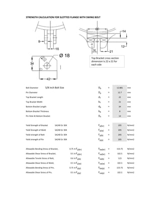
  • 1. STRENGTH CALCULATION FOR SLOTTED FLANGE WITH SWING BOLT Bolt Diameter 5/8 Inch Bolt Size Db = mm Pin Diameter Dp = mm Top Bracket Length dT = mm Top Bracket Width bT = mm Bottom Bracket Length dB = mm Bottom Bracket Thickness bB = mm Pin Hole At Bottom Bracket Dh = mm Yield Strength of Bracket  SA240 Gr 304 Fy(br) = N/mm2 Yield Strength of Weld SA240 Gr 304 Fy(w) = N/mm2 Yield strength of Bolt SA240 Gr 304 Fy(b) = N/mm2 Yield strength of Pin SA240 Gr 304 Fy(p) = N/mm2 Allowable Bending Stress of Bracket, x Fy(br) Fba(br) = N/mm2 Allowable Shear Stress of Bracket, x Fy(br) Fva(br) = N/mm2 Allowable Tensile Stress of Bolt,  x Fy(b) Fta(b) = N/mm2 Allowable Shear Stress of Weld, x Fy(w) Fva(w) = N/mm2 Allowable Bending Stress of Pin, x Fy(p) Fba(p) = N/mm2 Allowable Shear Stress of Pin,  x Fy(p) Fva(p) = N/mm2 153.75 102.5 21 34 8 14 123 12.881 12.7 205 205 205 102.5 153.75 205 22 102.50.5 0.75 0.5 0.6 0.5 0.75 Top Bracket cross section  dimension is 22 x 21 for  each side 14
  • 2. A) Shear Stress For Weld Attachment of Bracket/Shell Total Operating Bolt Load, WM1 (Read from PV Elite) WM1 = N Total Number of Bracket & Bolts N(b) = Operating Bolt Load Per Bracket & Bolt, F(b)=WM1/N(b) F(b) = N Top Bracket Total Weld Length Per Set of Bracket L(wtbr) = mm Fillet Weld Leg Size of Bracket F(wtbr) = mm Weld Shear Area, A(wtbr)=L(wtbr) xF(wtbr) A(wtbr) = mm2 Shear Stress (Max), Sv(wtbr)=F(b)/A(wtbr) OK Sv(wtbr) = N/mm2 Bottom Bracket Total Weld Length Per Set of Bracket L(wbbr) = mm Fillet Weld Leg Size of Bracket F(wbbr) = mm Weld Shear Area, A(wbbr)=L(wbbr) xF(wbbr) A(wbbr) = mm2 Shear Stress (Max), Sv(wbbr)=F(b)/A(wbbr) OK Sv(wbbr) = N/mm2 B) Bending Stress & Moment For Brackets (Per Set) Moment Arm For Bracket At Full Bolt Load  L(m) = mm Top Bracket Neutral Axis For The Set of Bracket y(tbr) = mm 2nd Moment of Area per Set of Bracket, I(tbr)=(bd3 )/12   I(tbr) = mm4 Bending Moment (Max), M(tbr)=F(b) x L(m) M(tbr) = N‐mm Bending Stress (Max), Sb(tbr)=M(tbr)/[I(tbr)/y(tbr)] OK Sb(tbr) = N/mm2 Bottom Bracket Neutral Axis For The Set of Bracket y(bbr) = mm 2nd Moment of Area per Set of Bracket, I(bbr)=(bd 3 )/12   I(bbr) = mm4 Bending Moment (Max), M(bbr)=F(b) x L(m) M(bbr) = N‐mm Bending Stress (Max), Sb(bbr)=M(bbr)/[I(bbr)/y(bbr)] OK Sb(bbr) = N/mm2 C) Shear Stress For The Bottom Bracket Due To Load At Point of Pin Contact Operating Bolt Load Per Bracket & Bolt, F(b)=WM1/N(b) F(b) = N Top Bracket Shear Area For The Bracket,  A(tbr) = mm2 Shear Stress (Max), Sv(tbr)=F(b)/A(tbr) OK Sv(tbr) = N/mm2 Bottom Bracket Shear Area For The Bracket,  A(bbr) = mm2 Shear Stress (Max), Sv(bbr)=F(b)/A(bbr) OK Sv(bbr) = N/mm2 924 7.85 136 2 272 26.67 10 10666.67 108830.83 102.03 29021.555 4 7255.39 0 0 0 32.12 544 7255.39 13.34 0.00 15 108830.83 37268.00 11
  • 3. D) Bending Moment, Bending Stress & Shear Stress For Pin Insert Through Bottom Bracket F1 = F2 = y= mm R1 = R2 = Max Bending Moment, M(p) = F x L M(p) = N‐mm Neutral Axis For The Pin y = mm 2nd Moment of Area, I(p)=πd 4  /64 I(p) = mm4 Max Bending Stress, Sb(p) = M/(I/y) OK Sb(p) = N/mm2 Shear Stress At Point Of Contact Between Pin And Bracket Cross section Area of Pin A(p) = mm2 Shear Stress (Max), Sv(p)=F(R1)/[SF x A(p)] SF=  0.5 OK Sv(p) = N/mm2 E) Axial Tension Of Bolt Root Area of Bolt A(b) = mm2 Shear Stress (Max), St(b)=F(b)/A(b) OK St(b) = N/mm2 F) Load Combination Top Bracket OK LC(tbr) = Bottom Bracket OK LC(bbr) = Pin OK LC(p) = 0.882 55.68 0.794 46.17 6.35 59.66 2.560 2.560 Bracket(bot) Width 0.286 130.313 3627.69 3627.69 1276.98 3627.69 3627.69 6.35 121.610 9285.08 18
  • 4. 14