The document outlines the process of manufacturing shells from plates at L&T's Hazira facility. The key stages include:
1. Preparing a plate cutting request to identify plates for cutting.
2. Cutting, marking, and inspecting plates according to the request.
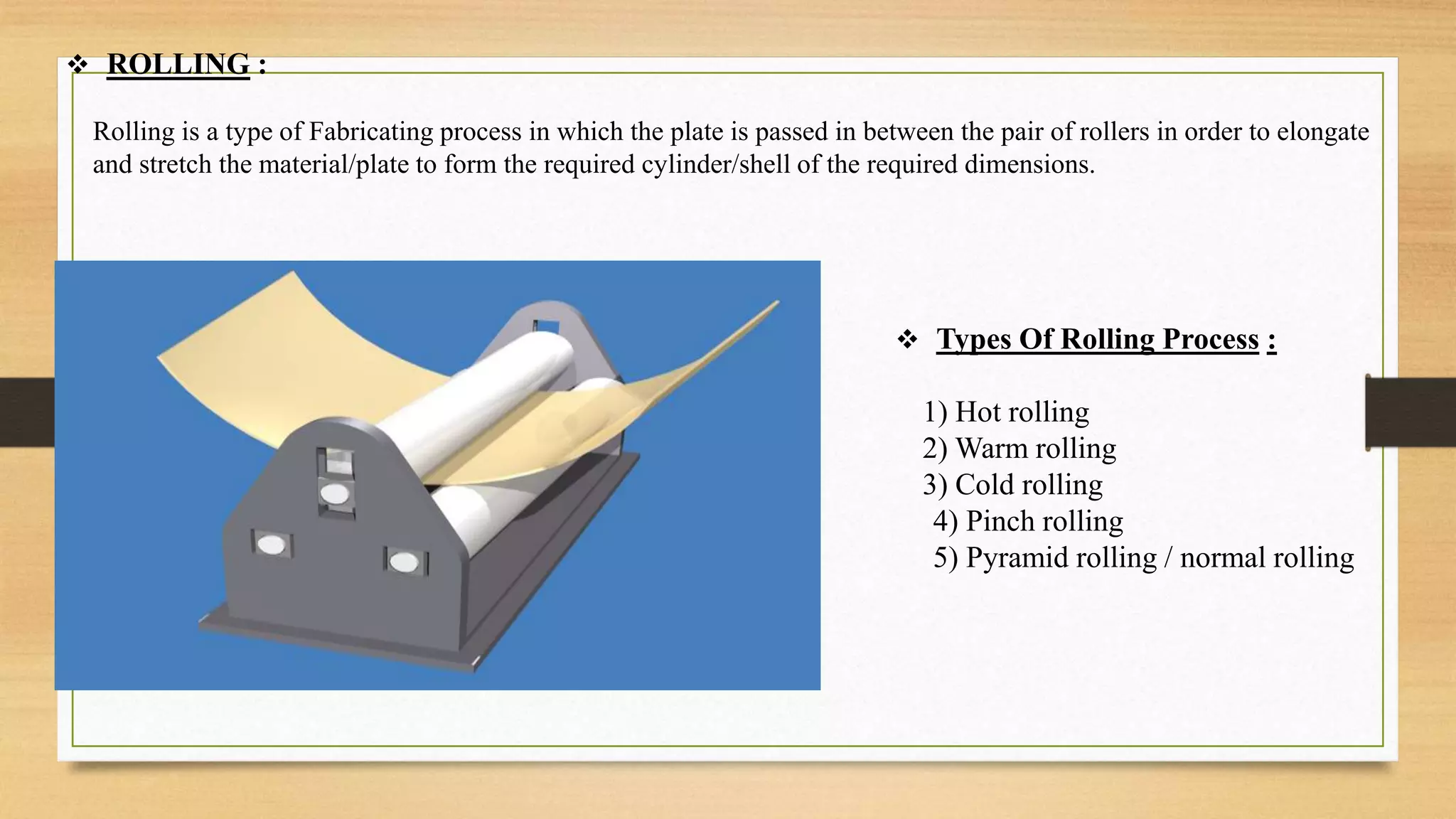
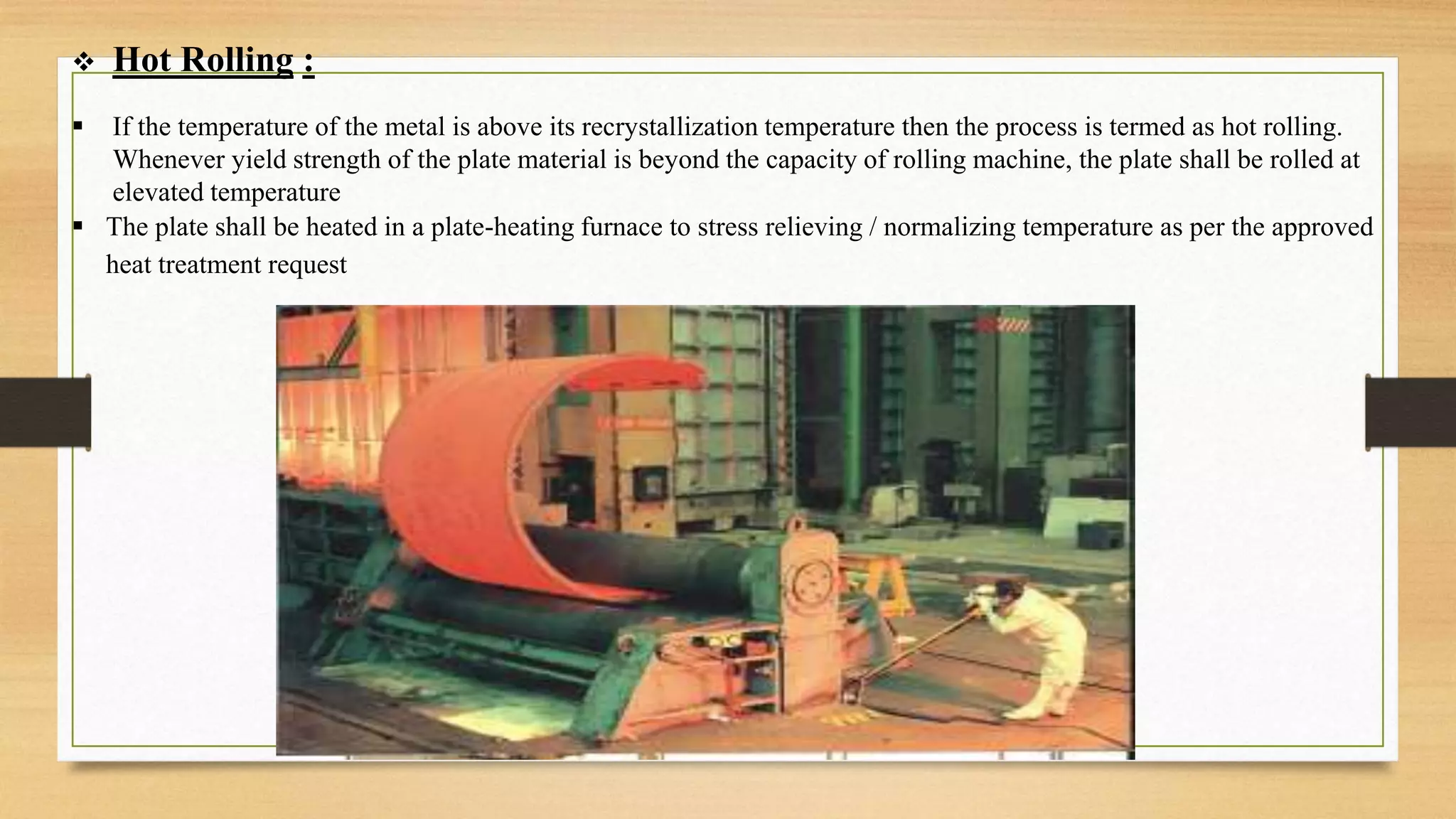
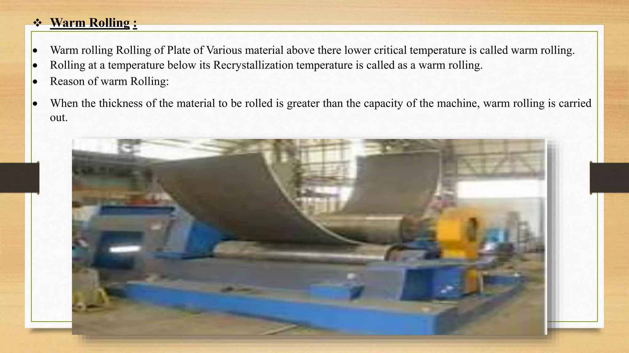
3. Rolling plates on large rolling mills to form cylindrical shells.
4. Setting up the long seam by positioning shell segments for joining.
5. Welding the long seam and inspecting it to form a complete shell.
![SR NO TOPIC PAGE
NO
1 Introduction Of L&T 4
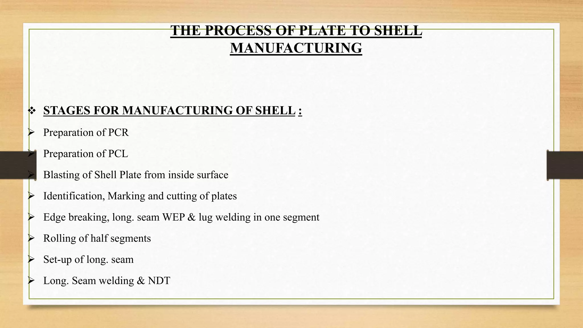
2 Stages For Manufacturing Of Shell 7
3 Stages Of PCR [ Plate Cutting Request] 8
4 Identification, Marking And Cutting Of Plates 8
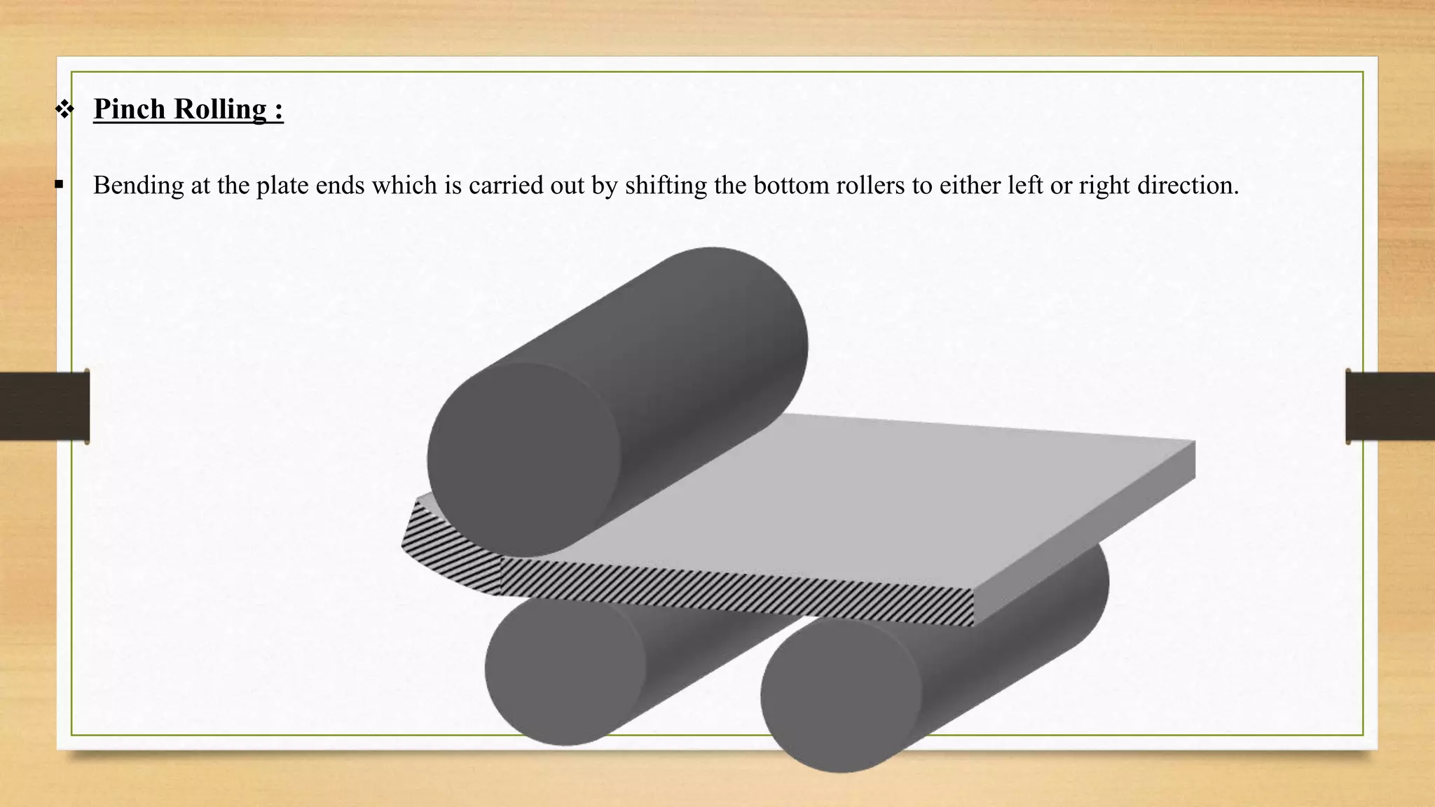
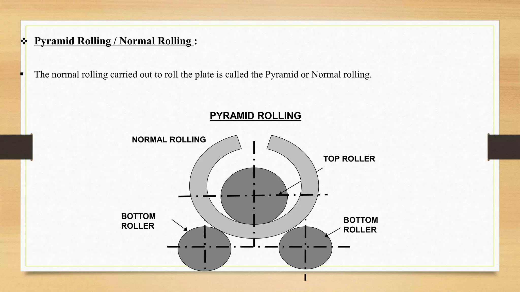
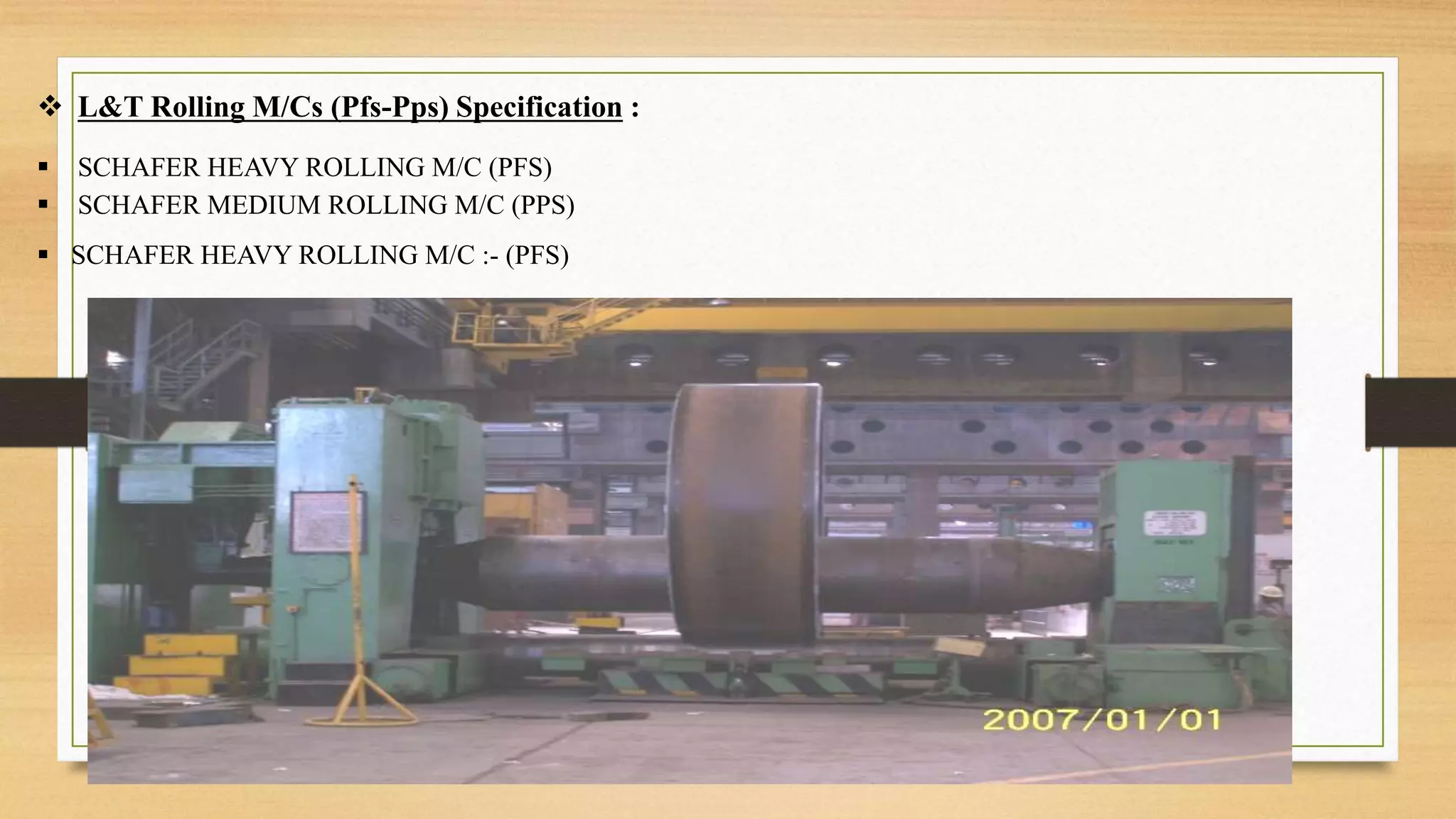
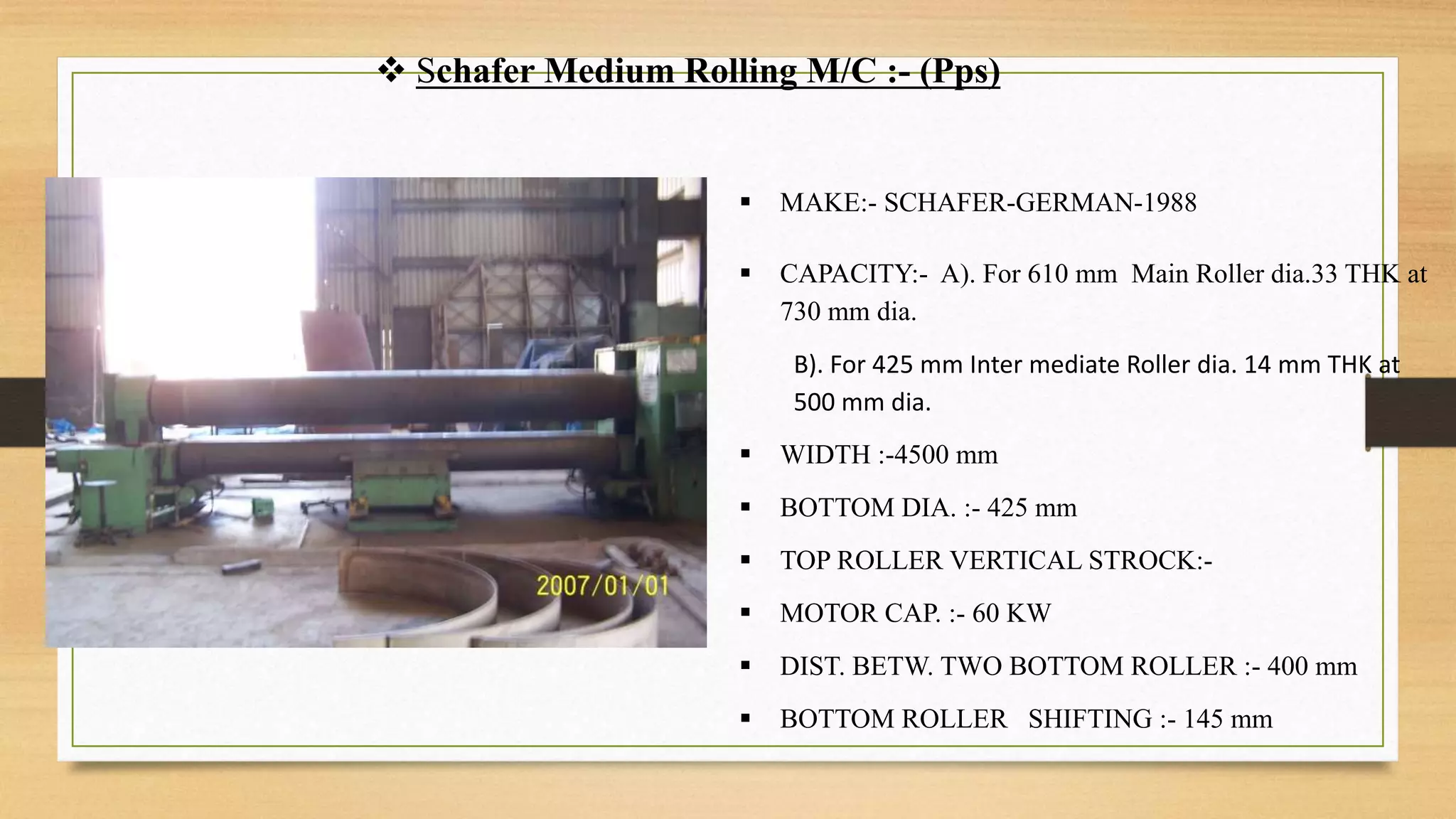
5 Rolling & Rolling Process 12
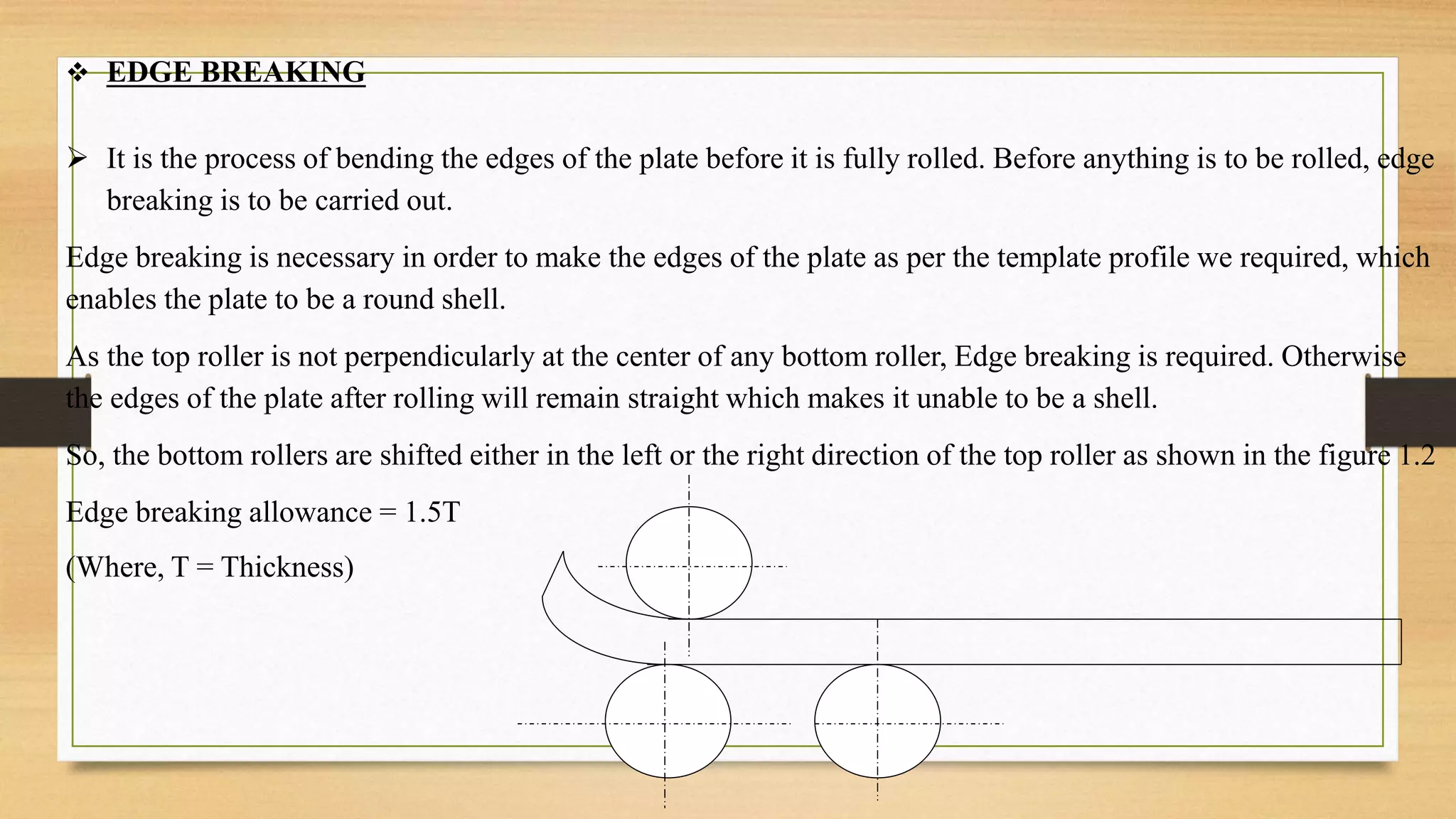
6 Edge Breaking 16
7 Rolling Selection Factors 17
8 Shell Inspection After Rolling 21
9 Long Seam Set-Up 21
10 Problem Can Occur While Long Seam Set-Up 24
11 Offset Limits For Butt Welds As Per Code [ Asme Sec. Viii Div 1 ] 26
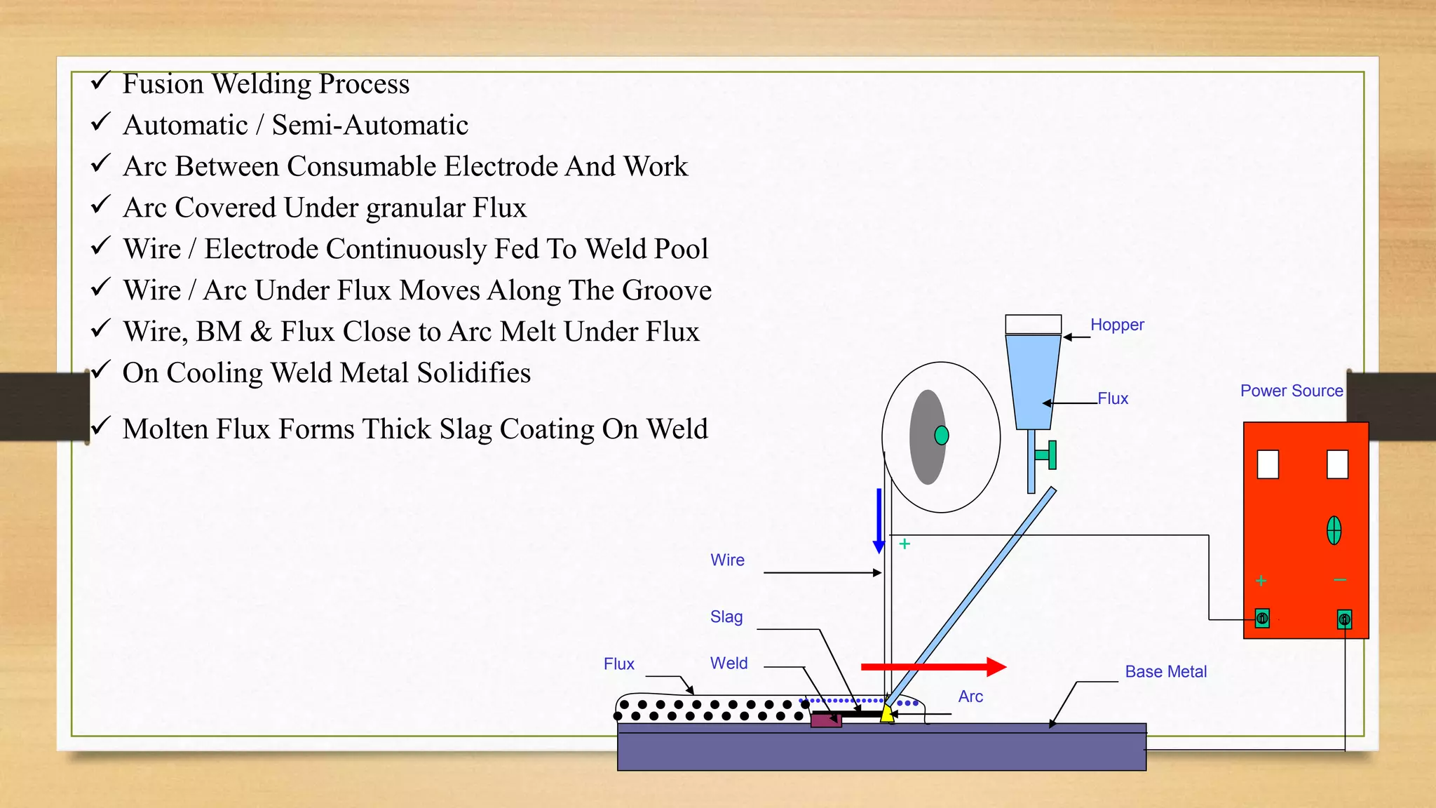
12 SAW Process 29
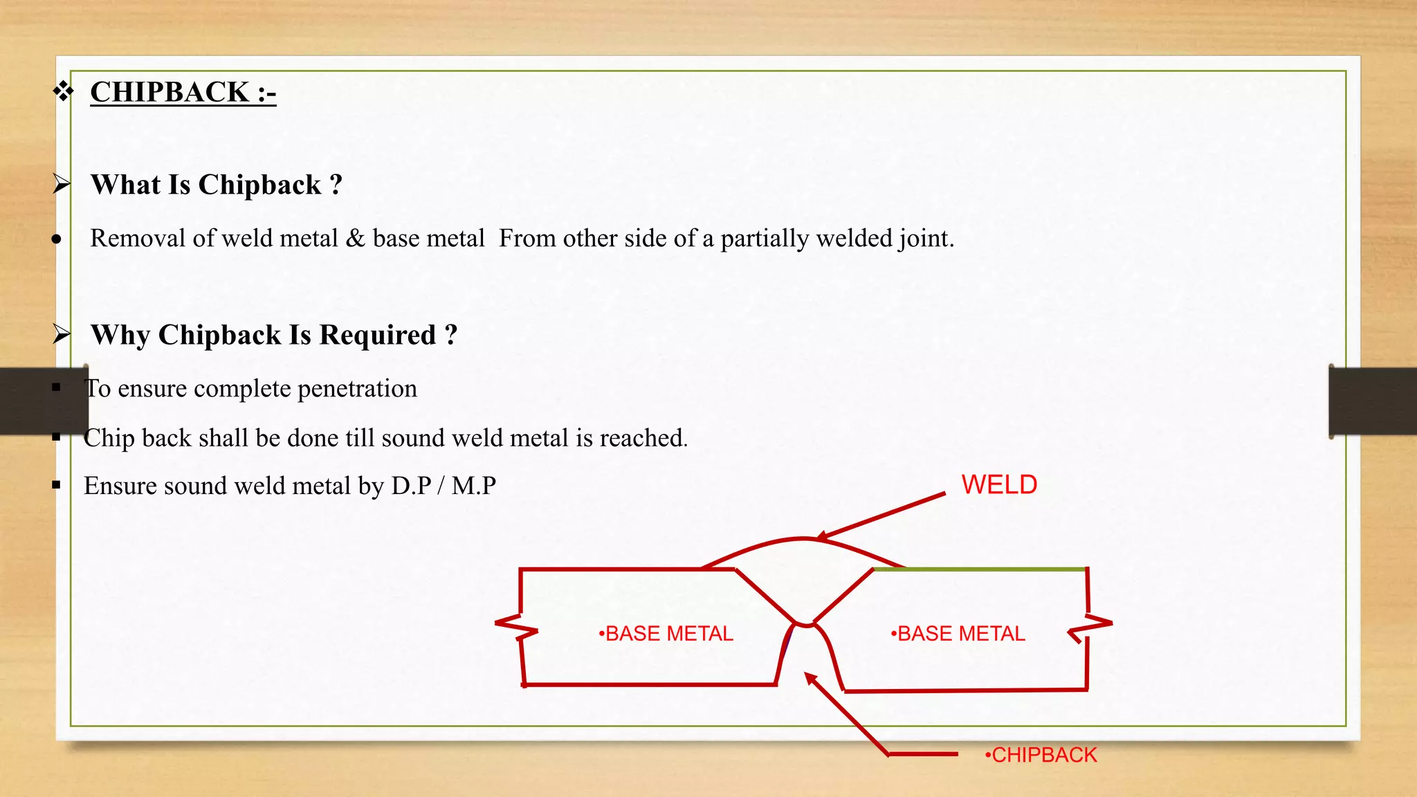
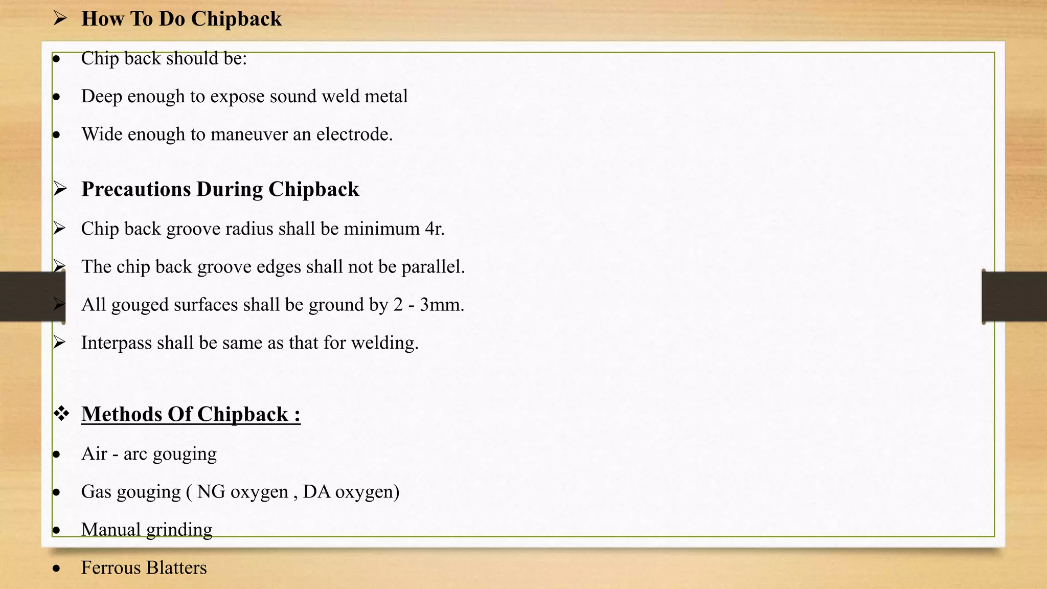
13 Chipback 31
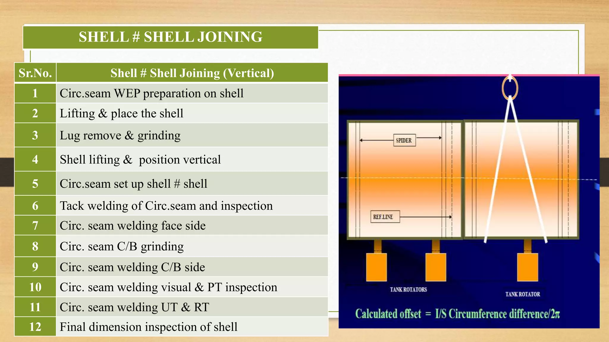
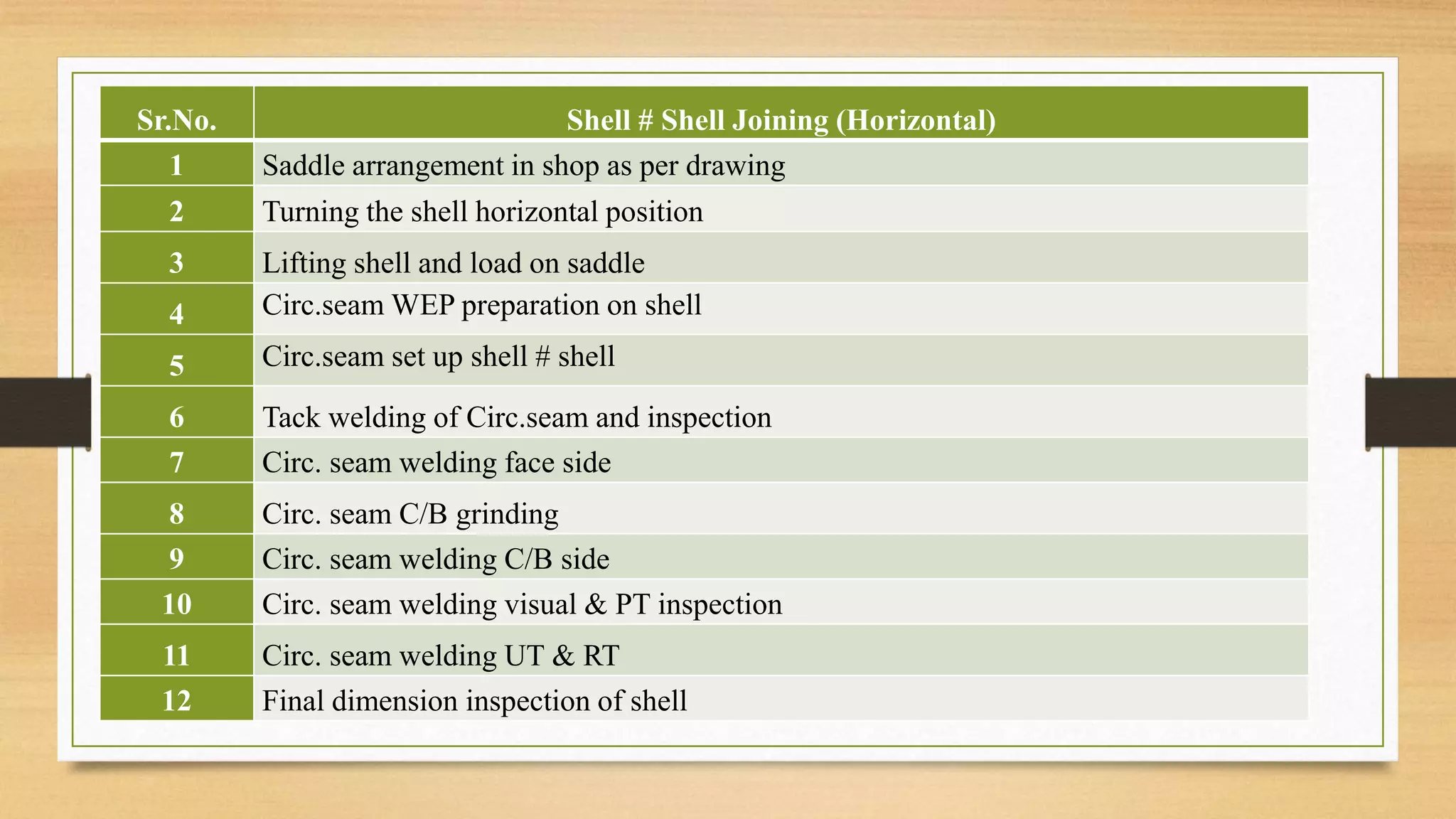
14 Shell # Shell joining 33
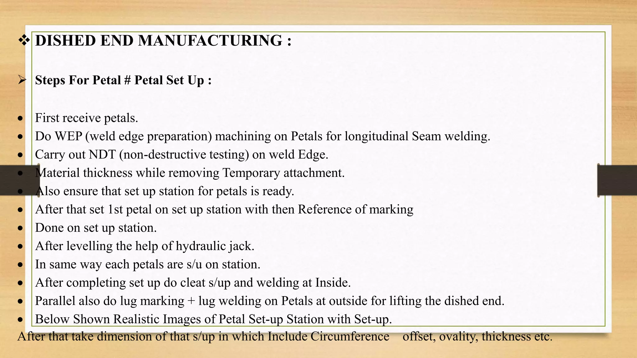
15 Dished End Manufacturing 35
16 Shell # Dished end joining 37
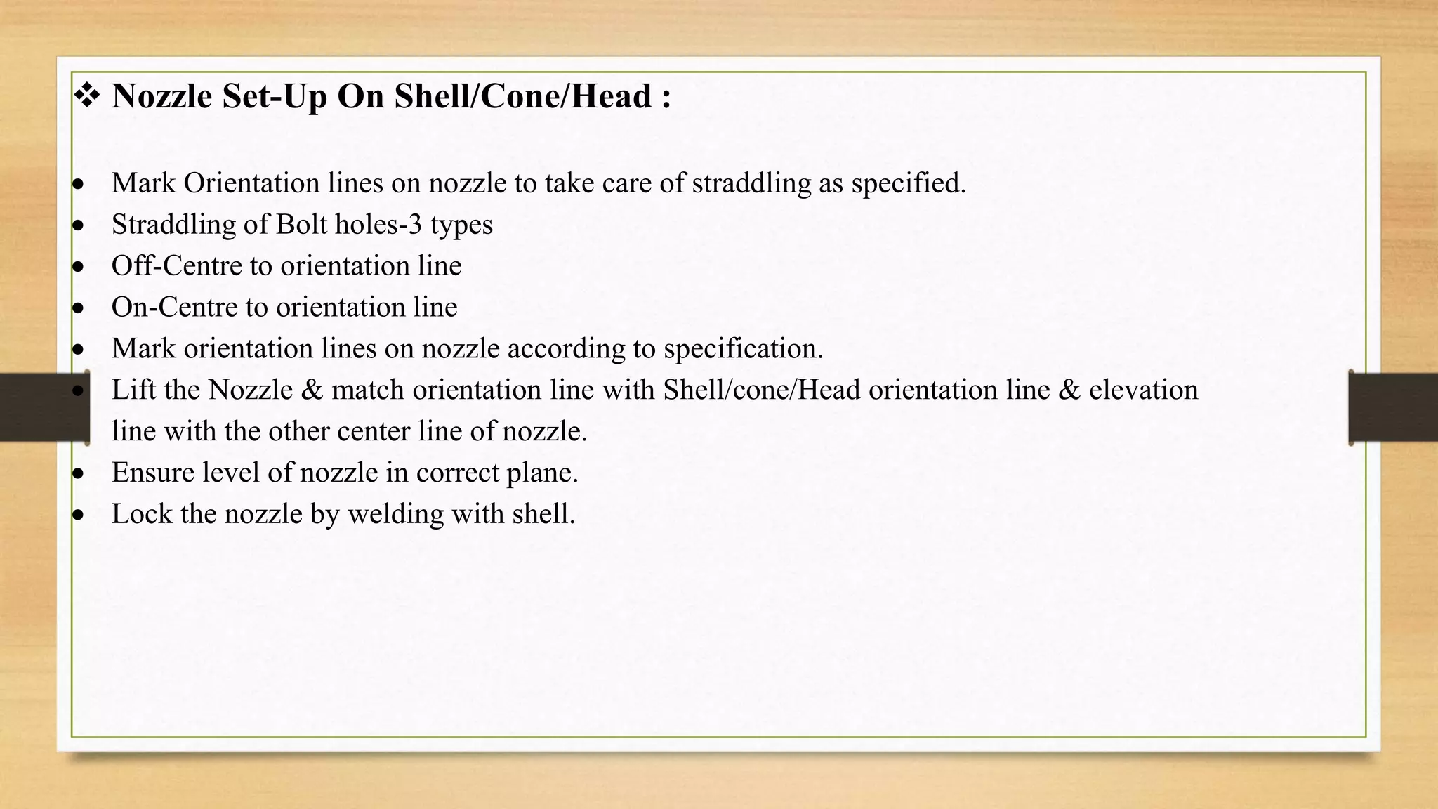
17 Nozzle Fabrication 40
18 Skirt Manufacturing Process 42
19 Skirt Installation Process 43
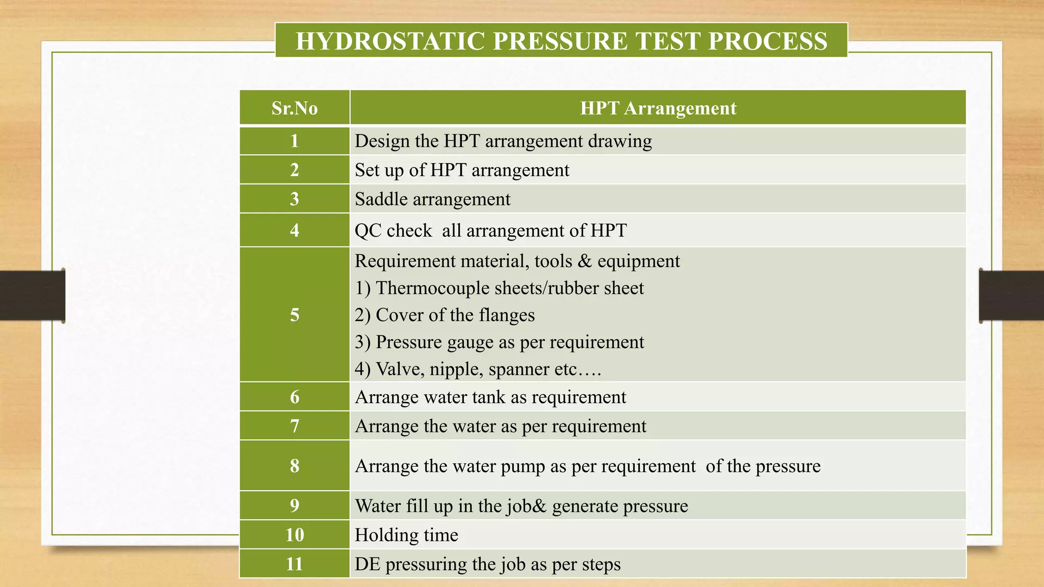
20 Hydrostatic Pressure Test Process 44](https://image.slidesharecdn.com/shelllfabrication-230131040110-4831d935/75/Shell-fabrication-pptx-2-2048.jpg)
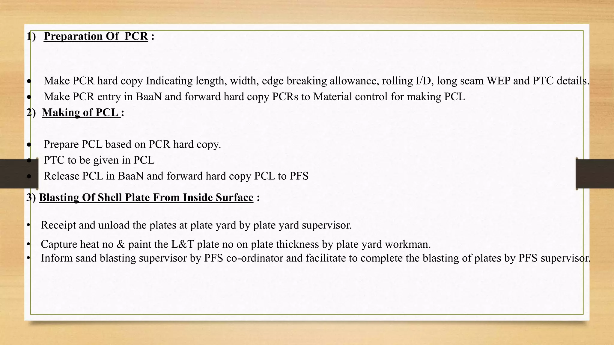
![1 DRG Release In System & Shop
2 PCR Preparation Based On Detailing
3 PCR Entry In System
4 PCL Preparation [ Plate Cutting Layout ]
5 QC First Stage Of Inspection And System Clearrence
6 SFC [ Shop Floor Co-ordination ] give time for marking and cutting
7 Store Issue Plate Base On Outbond & PCL
8 SFC IS Receive Plate And Start Marking
9 QC Is Inspection Marking And Give Permition For Cutting
10 SFC Complete Cutting & QC Give Stamp To Work Piece
11 Return Balance Plate is Send To Store & Store Is Close PCL
STAGES OF PCR [ Plate Cutting Request]](https://image.slidesharecdn.com/shelllfabrication-230131040110-4831d935/75/Shell-fabrication-pptx-8-2048.jpg)


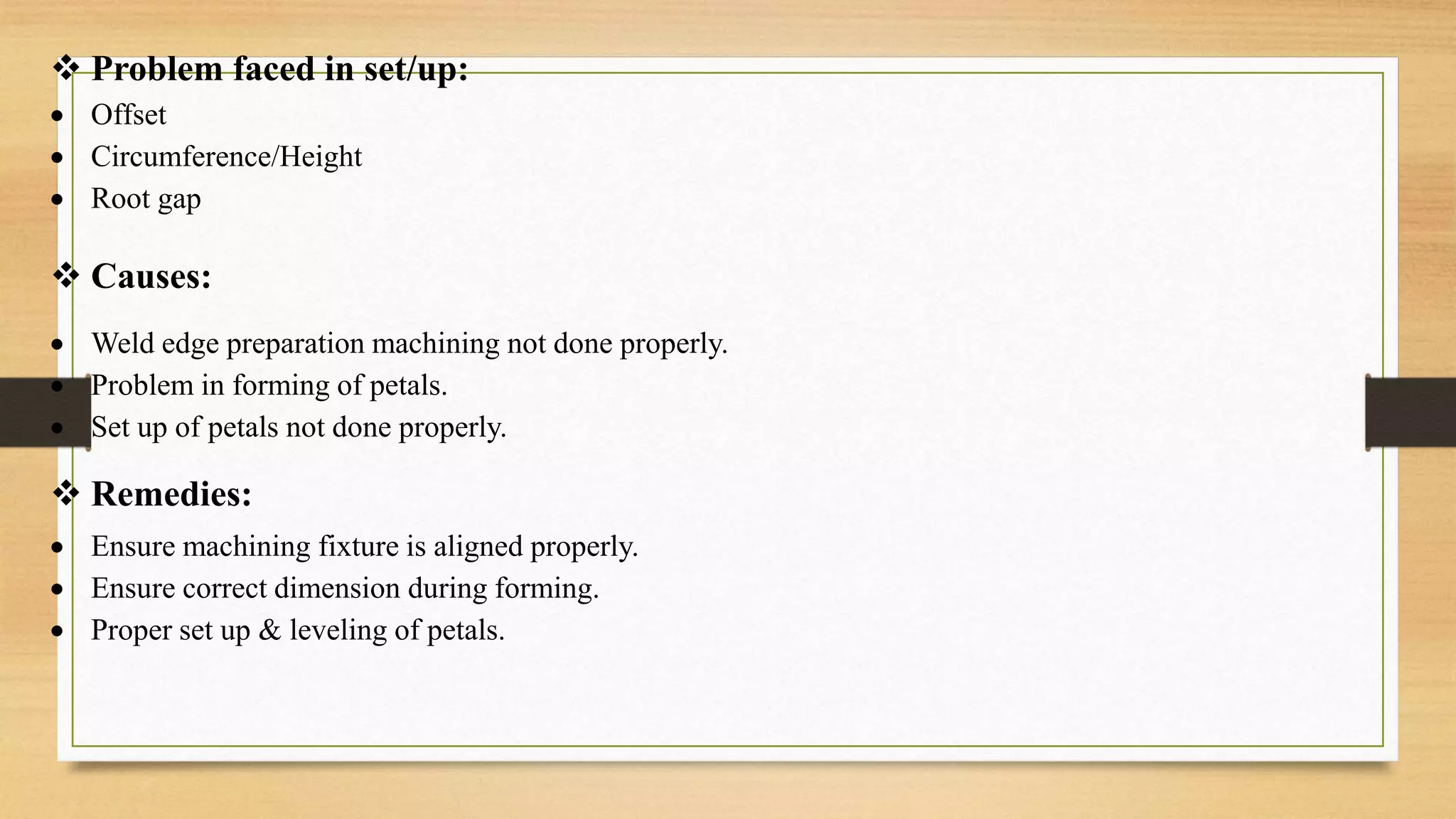
![ OFF-SET :
Thickness difference measured from I/s or o/s on joining
edges is called offset
Offset is found during
(A) Plate to Plate Set-up, Long Seam Set-up
(B) Circ. Seam Set-up
offset
OFFSET LIMITS FOR BUTT WELDS AS PER CODE [ASME SEC. VIII DIV 1 ]
MAXIMUM OFFSET IN BUTT WELD
JOINT THICKNESS "t" LONG SEAM (CATEGORY A)
13 MM & ELBOW 1/4th t
Over 13 mm to 19 mm 3.2 mm
Over 19 mm to 38 mm 3.2 mm
Over 38 mm to 51 mm 3.2 mm
Over 51 mm 1/16th t. max. 10 mm](https://image.slidesharecdn.com/shelllfabrication-230131040110-4831d935/75/Shell-fabrication-pptx-34-2048.jpg)
![ The we check the offset, found ok
Then we attach run in - run out plates & PTC as per job requirement.
Recheck the circumference at both the ends & at center.
O/S CIRC: 18286 MM
Then check the ovality by distometers,
1) Ovality 2 mm
2) Circularity 10 mm
After clear all the steps Offer the set-up for inspection
Long Seam Welding :
Long seam welding is a process which is use for joining of two segments to make a
shell.
SAW [Submerged Arc Welding] is used in the long seam welding process in the PFS.
Preheating is required for minimum temperature Before the long seam welding
process.](https://image.slidesharecdn.com/shelllfabrication-230131040110-4831d935/75/Shell-fabrication-pptx-36-2048.jpg)