
Recommended
More Related Content
What's hot
What's hot (20)
Similar to dlw taining file
Similar to dlw taining file (20)
Recently uploaded
Recently uploaded (20)
dlw taining file
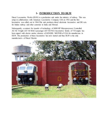
- 1. 1- INTRODUCTION TO DLW Diesel Locomotive Works (DLW) is a production unit under the ministry of railway. This was setup in collaboration with American Locomotive Company USA in 1961 and the first locomotive was rolled out in 1964.This unit produces diesel electronic locomotive and DG sets for Indian railway and other customer in India and Abroad. Subsequently a contract for transfer of technology of 4000 HP Microprocessor Controlled AC/AC Freight (GT 46 MAC) passenger (GT 46 PAC) locomotive family of 710 engine has been signed with electro motive division of GENERL MOTOR of USA for manufacture in DLW. The production of these locomotive has now started and thus DLW is the only manufacturers of Diesel Electric
- 2. 1.1 Brief History: Set up in 1961 as a green-field project in technical collaboration with ALCO/USA to Manufacture Diesel Electric Locomotives. First locomotive rolled out and dedicated to nation in January, 1964. Transfer-of-Technology agreement signed with General Motors/ USA in October, 95 to manufacture state-of-the-art high traction AC-AC diesel locomotives. A flagship company of Indian Railways offering complete range of flanking products in its area of operation. State-of-the art Design and Manufacturing facility to manufacture more than 150 locomotives per annum with wide range of related products viz. components and sub-assemblies. Unbeatable trail-blazing track record in providing cost-effective, ecofriendly and reliable solutions to ever-increasing transportation needs for over three decades. Fully geared to meet specific transportation needs by putting Price-Value Technology equation perfectly right. A large base of delighted customers among many countries viz. Sri Lanka, Malaysia, Vietnam, Bangladesh, Tanzania to name a few, bearing testimony to product leadership in its category. 1.2 Salient Features: Annual production capacity 125 Locomotives Annual turn-over (Rs) 5000 million Total number of staff 7223 Workshop land 89 Hectares Township area 211 Hectares Covered area in shops 86300 m2 Covered area of other service buildings 73700 m2 Electrical power requirement 3468 KVA (Average maximum demand) Electrical energy consumption (units/year) 19.8 million Standby power generation capacity 3000 KW
- 3. .1.3 Productof DLW: DLW is an integrated plant and its manufacturing facilities are flexible in nature. These can be utilized for manufacture of different design of locomotives of various gauges suiting customer requirements and other products. The product range available is as under: WDG4 4000 HP AC/AC Freight Traffic Locomotive WDP4 4000 HPAC/AC Broad Gauge High Speed Locomotive WDG3D 3400 HP AC/AC Broad Gauge Mixed Traffic Micro-Processor Controlled Locomotive. WDM3C 3300 HP AC/DC Broad Gauge Mixed Traffic Locomotive. WDM3A 3100 HP AC/DC Broad Gauge Mixed Traffic Locomotive. WDP3A 3100 HP AC/DC Broad Gauge High Speed Passenger Locomotive. WDG3A 3100 HP AC/DC Broad Gauge Freight Locomotive. WDG4 4000 HP AC/AC Freight Traffic Locomotive WDP4 4000 HPAC/AC Broad Gauge High Speed Locomotive WDG3D 3400 HP AC/AC Broad Gauge Mixed Traffic Micro-Processor Controlled Locomotive. WDM3C 3300 HP AC/DC Broad Gauge Mixed Traffic Locomotive. WDM3A 3100 HP AC/DC Broad Gauge Mixed Traffic Locomotive. WDP3A 3100 HP AC/DC Broad Gauge High Speed Passenger Locomotive. WDG3A 3100 HP AC/DC Broad Gauge Freight Locomotive. 1.4 DesignOffice: Prepare diag. of each part and sent to Material Control & inform timely in any change in any parts to relative department.
- 4. 2-LOCO FRAME SHOP A locomotive frame is the structure that forms the backbone of the railway locomotive, giving it strength and supporting the superstructure element such as a cab, boiler or bodywork. The vast majority of locomotive have had a frame structure of some kind. The frame may in turn be supported by axles directly attached to it or it may be mounted on bogies (UK)/trucks (US), or a combination of two. The bogies in turn will have frames of their own. 2.1 Types of frame: Plate frames These used steel plates about 1-2 in (25.4-50.8 mm) thick. They were mainly used in Britain and continental Europe. On most locomotive the frames would be situated with in the driving wheel but some classes of early steam locomotive and diesel shunters were constructed with outside frames some early designs were double frame where the frame consisted of plates both inside and outside the driving wheels. Others were sandwich frames where the frame was constructed of wood sandwiched between two metal plates.
- 5. Bar Frames: These were made of two steel bars which are usually 4-7 in (101.6-177.8 mm) thick. They were first used on the Bury Bar Frame locomotive during the 1830s, and were widely used in the USA throughout the nineteenth century.
- 6. SteelFrames: Cast steel locomotive beds were a development of the final years of steam locomotive design in the United State. They were also exported to Britain and Australia from the USA.
- 7. Articulated locomotives: An articulated locomotives with no fixed wheels (i.e. excluding the mallet locomotive but including other articulated steam locomotives, as well as most diesel and electric locomotives) may have a separate frame beneath the superstructure or the bodywork internal structure may be load-bearing. Rarely is a true mono structure used. Diesel and electric locomotive with a traditional, full width body, known as cab units in North America tend to have their strength in an internal structure. This style of construction is still popular elsewhere, but North American locomotive nowadays are overwhelmingly hood unit with a strong frame beneath the superstructure that carries all the load and bodywork made or removable panels for easy maintenance. Fully enclosed locomotive are used in some limited application, mostly for passenger train. These tend to be cowl unit, in which the body is not load-bearing.
- 8. 3-Loco Paint Shop The work of this shop is to paint the coaches and bogie. In this shop there are many section and they are following 1-COACH PAINTING. 2-LETTER SECTION. 3-CORROSION SECTION. 4-POLISH SECTION. 3.1 Purpose of Painting:- 1-FORPROTECTION AGAINST COROSION. 2-FORDECORATION. 3-FORCOVERING. 3.2 MaterialUsed in Painting:- 1-PAINT MATERIALS. 2-ENEMAL MATERIALS. 3-VARNISH MATERIALS. 4-LACQUER MATERIALS. 3.3 Paint Materials:- 1-BASE. 2-BINDER. 3-THINNER. 4-DRIER. 5-PIGMENT. 6-INERT OR FILLER MATERIAL. 3.4 The Main ProcessInvolve in Painting:- Firstly, Putin is prepared and it gets filled at the places where holes and cracks has been found. Secondly the primer is put primer is put on the body and then finally painting is done in order to give the body desire shape.
- 9. The overhauling of the coaches has been in given time interval it improves the quality of coaches and it also prevents the coaches from break down. The maintenance of coaches is according to time being is done as following 1-MAIL EXPRESS 12 MONTHS 2-PASSENGER. 18 MONTHS 3-NEWLY COACHES. 24 MONTHS 3.5 Types of Pant:- 1-Aluminum paint. 2-Anti-corrosive. 3-Asbestos paint. 4-Bituminous paint. 5-Cellule paint. 6-Cement paint. 7-Distemper. 8-Plastic paint 9-Graphite paint. 10-Oil paint. 11-Silicate paint. 12-Luminous paint. 13-Enamel paint. 14-Emulsion paint. 4-Engine Erection Shop (E.E.S):- This shop deals with different sub assembly and different items of engine. There are six section. 4.1 Paint section This section deals with the cleaning debarring of cylinder block. 4.2 Pistoncranks shaft and cylinder erection a- Open and remove main brag caps. b- Fitting of liner sleeve.
- 10. c- Fitting of camshaft and bushing. d- Fitting of cylinder head studs. e- Fitting of cylinder liner 4.3 Cylinder head erection a- Sub assembly of crank shaft crankshaft gear. b- Sub assembly of piston and connecting rod. c- Fitting of cylinder head. d- Fitting of water connection. e- Fitting of exhaust manifold. 4.4 Generatorcam shaft controlshaft and turbo application a- Fitting of oil catcher. b- Fitting of generator mounting block. c- Fitting of air duet support d- Fitting of main generator and marking pointer. e- Fitting of fuel oil header. f- Fitting of control shaft. g- Fitting of cam shaft and cam shaft gear. h- Fitting of os trip i- Fitting of turbo support. j- Fitting of after cooler. k- Fitting of spacer. l- Fitting of turbo charger with water collector. m- Fitting of water piping. 4.5 Fuel pump and valve lever a- Fitting of fuel filter. b- Fitting of fuel pump support. c- Fitting of fuel pump. d- Fitting of governor mounting. e- Fitting of push rod. f- Fitting of valve lever g- Fitting of valve lever clearance. 4.6 Piping and miscellaneous a- Fitting of all piping
- 11. b- Fitting of F.P. support. c- Fitting of lube oil strainer. d- Fitting of cam shaft gear cover. e- Fitting of explosion cover. 5-INTRODUCTION TO LIGHT MACHINE SHOP This shop deals with the matching of various small components required for the power pack unit such as, cam shaft, connecting rod, liners, gears, levers, F.P. Support, Piston pin, nuts and bolts bushes, various shafts etc. 5.1 The light machine shop divided into the following section:- 1. Econometric Section 2. Gear section 3. Grinding section 4. Cam shaft section 5. A.T.L. section 6. Belching section 7. Connecting rod section 8. Lathe section
- 12. 9. Liners section 10. Drilling section 11. Milling section 1-Econometric section: This section manufacturing various sizes etc. 2- Gearsection: Econometric machine, do-all machine, belt grinding machine (for control shaft feed) This section deals to making various gears impeller such as: cam shaft gear, crank shaft gear, extension shaft gear, impeller gear (follower & drive) and broaching Machine Provided:- Gear hobbling machine (a) Gear hobbling machine
- 13. (b) Gear shaving machine (c) V.T.L. machine (d) Radial drilling machine (e) Broaching machine (f) Centre mill M/C 3- Grinding Section: In this section the various small components are grinding as per required finishing after machining operation and each components having grinding allowance (G.A.) main piston pin, impeller and fuller and follower gear, pin valve guide, various studs. Cam roller, seat (V/C Q ‘X’ head) spider various bushes etc. Machine provided: a. Cylindrical grinding machine b. Internal grinding machine c. Centre less grinding machine d. Thread rolling machine e. Universal grinding machine f. External grinding machine 4. Camshaftsection:
- 14. This section making cam shaft (both B.G. & M.G.) with completed machining operation by various special type of machine. In B.G. 08 no’s per loco and in M.G. 03 per loco. 5. Automatic Turret Lathe (A.T.L) Section: This section manufacturing various types of small components for Power pack engine such as: Lock spring seat (V/L & X-Hd) spewing seat. Ball end, cup end ad. Screw (X-HD & V/L) cop screws L.A.S. retainer, spring lever, F.P. inlet, Porg Bkt. piston pin liner sleeve, body outer ring spicier etc. Machine Provided: 1. M.T.L. (Bar type, chuck type) 2. U.T.L. The A.T.L. section is the vital section of this shop. Maximum small components are manufacturing in the section. 6. Benching Section: In this section the benching operation of the entire component which are manufacturing in the shop are done here. In the benching section, there hawing hand cutter machining and belt grinding machine, with the half of these machine bar removing from all the components. 7. Connecting rod section: In this section the connecting rod is made. All the machining operations of the connecting rod, completed here with the help of various types of machine. The connecting rod has two parts, one is cap and other is rod. The material of the connecting rod is steep forging. In B.G. 16 per loco and in M.G. 6 per loco. Main dimensions: 1. Crank bore (big bore) =6-411” to 6.421” 2. Piston pin bore (small bore) =3.998” to 3.999” 3. Distance Between Two = 20.995” to 21.000” bare Centre 4. Rod Thickness = 3.020” to 3.022” 5. Weight = 32 Kg 950 gram to 32 Kg gram. 6. Pressure Torque = 150 P.S.I.
- 15. 8. Lathe section: This section deals various types tropical small components are manufacturing. Centre lath machines oar provided in this section. The components are: brass sleeve, wear plate, valve guide, long stud, shaft etc. In drum type turret lathe M/C manufacturing pin cam roller, cup end, bush washer etc. 9. Cylinder Liner Section: In this section .cycle liner machine operation have done here by the various type of m/cs. the material of the cylinder Liner is special Cast iron and the set the per loco is in B.G. 16 and in M.G. 6 cylinder. Main Dimension:- 1. Length 21 15/16 + 1/64 2. Inside dia. rough honing -9.010” 3. Inside dia. finish honing – 9.015”
- 16. 4. outside dia. – 10.00” 5. Dia. of groove – 10.749 to 10.750” Machine provided:- 1. Shot blast machine. 2. Vertical boring machine 3. Auto lathe machine. 4. Honing machine. 5. Cylindrical grinding machine. 10. Drilling Section: In this section dials with various Types of drilling, reaming, counter bore spot tracing and counter sinking operation done of various small components. The components are, F.P. support, P.R. Lighter, X head, Valve Lever, Spring Lever, Brg, Bracket, Pin, Ecc Lever, Upper housing etc. Machine Provided:- 1. Radial drilling Machine, 2. Gang drilling machine of multy spindle drilling machine 3. Drilling Machine 4. Electronic drilling machine. 11. Milling Machine:- This section manufacturing various types of milling operation of the components in different types of milling machine- Machine Provided:- 1. Vertical milling machine 2. Horizontal milling machine 3. Universal milling machine. 6-INTRODUCTION TO MACHIN SHOP Machine shop work is generally understood to include all cold-metal work by which an operator, using either power driven equipment or hand tools, removes a portion of the metal and shapes it to some specified form or size. It does not include sheet metal work and copper smithing. The function of all machine tools is to produce metal parts by changing the shape, size, or finish of a piece of material. The shape of a part made with a machine toolis limited by the types of motion the tool can apply. Standard machine tools are grouped in six basic classes: 1. LATHES 2. DRILLING MACHINES 3. SHAPERS 4. PLANERS 5. MILLING MACHINES 6. GRINDING MACHINES 6.1 LATHE:
- 17. The lathe is used for turning various metals against a cutting tool that shapes it to the desired product. The engine lathe is a machine tool that produces a cutting action by rotating the work piece against the cutting edge of the tool. 6.2 DRILLING MACHINES: The drilling machine is a machine tool that produces the necessary cutting action by the rotation of a multiple edge cutting tool. 6.3 SHAPING AND PLANING MACHINES: Both of these machines can machine flat surfaces with a single point reciprocating, motion is applied to both the work piece and tool in these machines. 6.4 MILLING MACHINES: A milling machine provides cutting action to a rotating tool. The vertical milling machine is used to cut, shape, and finish metal objects. 6.5 GRINDING MACHINES A grinder differs from other machines in that it uses a tool made of emery, Carborundum, or similar materials. The wheel, made up of many tiny cutting points, cuts with the entire surface area that comes in contact with the material being ground. Grinders cut with a grinding action, removing material in the form of tiny particles. 6.6 SAFETYRULES FOR MACHINE TOOLS: 1. Gears, pulleys, belts, couplings, ends of shafts having keyways, and other revolving or reciprocating parts should be guarded to a height of 6 feet above the floor. The guards should be removed only for repairing or adjusting the machine and must be replaced before operating it. 2. Safety setscrews should be used in collars and on all revolving or reciprocating members of the machine tool or its equipment.
- 18. 3. Do not operate any machine tool without proper lighting. 4. Never attempt to operate any machine tool until you fully understand how it works and know how to stop it quickly. 5. Never wear loose or torn clothing and secure long hair, since these items can become caught in revolving machine parts. Ties should be removed and shirt sleeves should be rolled up above the elbow. 6. Gloves should never be worn when operating machinery except when absolutely necessary. 7. Always stop the machine before cleaning it or taking measurements of the work piece. 8. Do not lubricate a machine while it is in motion. Injury to the operator and damage to the machine may result from this practice. 9. Always wear safety glasses or goggles while operating machine tools. Also, wear respiratory protection if operation creates hazardous dust. All persons in the area where power tools are being operated should also wear safety eye protection and respirators as needed. 10. Know where tire extinguishers are located in the shop area and how to use them.
- 19. 11. Never wear jewelry while working around machine tools. Rings, watches, or bracelets maybe caught in a revolving part which could result in the hand being pulled into the machine. 12. Avoid horseplay. Tools are very sharp and machines are made of hard steel. An accidental slip or fall may cause a serious injury. 13. Never use compressed air without a safety nozzle to clean machines or clothing. It will blow sharp, dangerous metal chips a long distance.
- 20. 14. Never place tools or other materials on the machine table. Cluttering up a machine with tools or materials creates unsafe working conditions. Use a bench or table near the machine for this purpose. 15. Always use a rag when handling sharp cutters such as milling cutters and end mills. 7-INTRODUCTION OF HEAVY WELDING SHOP: In the DLW there are basically three type of welding used in HWS. The welding quality of DLW is very high quality. After the machining process we can’t say that this piece is not single piece. 1. Submerged arc welding 2. Manual metal arc welding 3. MIG welding 7.1 SUBMERGED ARC WELDING: In submerged arc welding the welding process will be covered with the flux so that it will not react with oxygen and nitrogen. Because of the versatility of the process and the simplicity of its
- 21. equipment and operation, shielded metal arc welding is one of the world's most popular welding processes. It dominates other welding processes in the maintenance and repair industry, and though flux- cored arc welding is growing in popularity, SMAW continues to be used extensively in the construction of steel structures and in industrial fabrication. The process is used primarily to weld iron and steels (including stainless steel) but Aluminum nickel and copper alloys can also be welded with this method. 7.2 GMAWCOMPONENTS: 1. DC or Direct Current power supply 2. Electrode or wire feed controller 3. Wire drive roller assembly 4. Shielding gas source (cylinder) & regulator 5. Manually held Gun & ground clamps 6. Wire reel
- 22. 7.3 MIG WELDING: MIG welding can be used for most types of metals; steel, stainless steel, as well as aluminum. But welding aluminum is very different from welding mild steel because aluminum is a metal that is different from steel. So when we weld aluminum, we have to use other parameters, other settings. Aluminum has a lower melting temperature than mild steel, for example, so you should expect that we should use a lower heat input but in spite of this. So we have to use a higher local heat-input but a faster welding speed than with steel to get good fusion and penetration. This sounds as if aluminum welding is difficult, but it's not. The welding sets that we use adjust the welding parameters automatically, so the welder can concentrate on the welding operation, the movement of the welding gun and the weld pool.
- 23. INDEX SerialNumber Content 1. Introduction to DLW 1.1 Brief History 1.2 Salient Features 1.3 Product of DLW 1.4 DesignOffice 2. LOCO FRAME SHOP 2.1 Types of frame 3. Loco Paint Shop 3.1 Purpose of Painting 3.2 Material Usedin Painting 3.3 Paint Materials 3.4 The Main Process Involve in Painting 3.5 Types of Pant 4. Engine Erection Shop 4.1 Paint section 4.2 Piston cranks shaft and cylinder erection 4.3 Cylinder head erection 4.4 Generator cam shaft control shaft and turbo application 4.5 Fuel pump and valve lever 4.6 Piping and miscellaneous 5. INTRODUCTION TO LIGHT MACHINE SHOP 5.1 The light machine shopdivided into the following section 6 INTRODUCTIONTO MACHIN SHOP 6.1 LATHE 6.2 DRILLING MACHINES 6.3 SHAPING AND PLANING MACHINES 6.4 MILLING MACHINES 6.5 GRINDING MACHINES 6.6 SAFETY RULES FOR MACHINETOOLS 7. INTRODUCTION OF HEAVY WELDING SHOP 7.1 SUBMERGED ARC WELDING 7.2 GMAW COMPONENTS 7.3 MIG WELDING 8. Conclusion