torsinal pendulum.docx
•Download as DOCX, PDF•
0 likes•231 views

Modulus of rigidity is an elastic constant. that measures the elastic behavior of a material when it is twisted or sheared. torsion pendulum consists of a weight of given shape hanged to the ceiling through a metallic wire, on twisting this load through an angle and left, it starts to oscillate, back and forth, The number of oscillations per unit time is measured. In this article the theory and experimental procedure of the measurement of modulus rigidity of the given metallic wire is presented by using the principle of torsional pendulum

Recommended
More Related Content
What's hot
What's hot (20)
Similar to torsinal pendulum.docx
Similar to torsinal pendulum.docx (20)
More from Praveen Vaidya
More from Praveen Vaidya (20)
Recently uploaded
Recently uploaded (20)
torsinal pendulum.docx
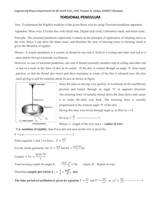
- 1. Engineering Physics Experiments for BE and B.Tech., Prof. Praveen N. Vaidya, SDMCET Dharwad. TORSIONAL PENDULUM Aim: To determine the Rigidity modulus of the given Brass wire by using Torsional pendulum apparatus. Apparatus: Brass wire, Circular disc with chuck nuts, Digital stop clock, Laboratory stand, and meter scale. Principle: The torsional pendulum experiment is based on the principle of application of shearing stress to the wire, hence it can show the shear strain, and therefore the ratio of shearing stress to shearing strain is given the Modulus of rigidity. Theory: A simple pendulum is a system of thread its one end is fixed to a ceiling and other end tied to a mass and let free give periodic oscillations. However, in case of torsional pendulum, one end of thread (normally metallic) tied to ceiling and other end is tied to a mass in the form of disc at its center. If the disc is rotated through an angle ‘θ’ from mean position, so that the thread also twists and show resistance to rotate, if the disc is released now, the disc starts giving to and fro rotations about its axis as shown in figure. Since the mass is moving very quickly, it overshoots at the equilibrium position and rotates through an angle ‘θ’ in opposite direction. The restoring force of metallic thread slows the mass down and causes it to rotate the other way back. The restoring force is actually proportional to the rotation angle ‘θ’ of the disc. During this time wire twists through angle φ, so that l φ = r θ Or or 𝜑 = 𝑟𝜃 𝑙 --------------------- 1 Where, l – length of the wire and r – radius of wire. If n- modulus of rigidity, then Force per unit area on the wire is given by, F = n φ ------------------------------------------------2 From equation 1 and 2 we have, 𝐹 = 𝑛𝑟𝜃 𝑙 For the whole perimeter 2πr, 𝐹 = 𝑛𝑟𝜃 𝑙 2𝜋𝑟𝑑𝑥 = 2𝜋𝑛𝑟2𝜃 𝑙 𝑑𝑥 𝐶𝑜𝑢𝑝𝑙𝑒 = 𝐹𝑥 = 2𝜋𝑛𝑟3 𝜃 𝑙 Total twisting couple for angle 𝜃, 2𝜋𝑛𝜃 𝑙 ∫ 𝑥3 𝑑𝑥 𝑅 0 where, R – Radius of wire Therefore,𝐜𝐨𝐮𝐩𝐥𝐞 𝐩𝐞𝐫 𝐭𝐰𝐢𝐬𝐭, 𝐂 𝐭 = 𝐂 𝛉 = 𝝅𝒏𝑹𝟒 𝟐𝒍 , also The time period of oscillation is given by equation 𝑇 = 2𝜋 𝜔 and 𝑇2 = 4𝜋2 𝜔2 or 𝜔2 = 4𝜋2 𝑇2 − − − − − −3
- 2. Engineering Physics Experiments for BE and B.Tech., Prof. Praveen N. Vaidya, SDMCET Dharwad. and ω = √Ct/I = √ 𝝅𝒏𝑹𝟒 𝟐𝒍 /I or ω2 = 𝝅𝒏𝑹𝟒 𝟐𝒍𝑰 ----------------------------- 4 Where, I – Moment of Inertia of circular disc is given by, 𝐼 = 1 2 𝑀𝑅2 R – Radius of Disc and M – Mass of the disc From 3 and 4 we have, 4𝜋2 𝑇2 = 𝜋𝑛𝑅4 2𝑙𝐼 , rearranging the term we get, 𝑛 = 8𝜋𝐼 𝑟4 × 𝑙 𝑇2 Procedure: Take the suitable length of brass wire and its one end is fixed at the center by means of chuck nut at the center of circular disc and this set up is suspended by means of a rigid support as shown in figure. Now rotate the circular disc about the axis of wire through some angle and leave, the disc is set to oscillate about its mean position. Note down the time taken to complete 10 oscillations using a stop clock. Now repeat the same procedure for different length and tabulate the readings. Determine the time period of oscillation and determine the value of L/T2 every time. Find out the mean value of L/T2 Measure the mass of the circular disc (M), Radius of the circular disc (R), Radius of the Brass wire using screw gauge (r). Determine the Modulus of rigidity of brass wire is given by equation 𝑛 = 8𝜋𝐼 𝑟4 × 𝑚𝑒𝑎𝑛 ( 𝑙 𝑇2), Where I is moment of Inertia of circular disc is given by 𝐼 = 1 2 𝑀𝑅2 . The graph is plotted taking T2 along Y-axis and L – along X – axis. Determine the slope. Therefore the Modulus of rigidity by graphical method is given by 𝑛 = 8𝜋𝐼 𝑟4 × 1 𝑠𝑙𝑜𝑝𝑒 Result: Modulus of rigidity of Brass wire is __________________ (By calculation) Modulus of rigidity of Brass wire is __________________ (By Graph) Experimental setup: Observations: Mass of the circular disc (M)______________ kg. Radius of the circular disc (R)____________cm = _________m Radius of the Brass wire (r)______________mm = _________m
- 3. Engineering Physics Experiments for BE and B.Tech., Prof. Praveen N. Vaidya, SDMCET Dharwad. Tabular column: Tr. No. Length of wire, L in m Time taken for 10 oscillations in seconds Time period, T in sec T2 L/T2 Trial -1 Trial -2 Trial -3 1 0.15 2 0.2 3 0.25 4 0.3 5 0.35 6 0.4 7 0.45 Calculation: