Young's modulus by single cantilever method
•
0 likes•7,705 views

Young's modulus is a method to find the elasticity of a given solid material. The present article gives the explanation how to perform the experiment to determine the young's modulus by the use of material in the form of cantilever. The single cantilever method is used here.

Recommended
More Related Content
What's hot
What's hot (20)
Similar to Young's modulus by single cantilever method
Similar to Young's modulus by single cantilever method (20)
More from Praveen Vaidya
More from Praveen Vaidya (20)
Recently uploaded
Recently uploaded (20)
Young's modulus by single cantilever method
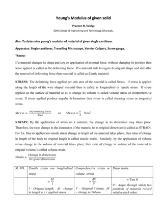
- 1. Young’s Modulus of given solid Praveen N. Vaidya SDM College of Engineering and Technology, Dharwad. Aim: To determine young’s modulus of material of given single cantilever. Apparatus: Single cantilever, Travelling Microscope, Vernier Calipers, Screw gauge. Theory: If a material changes its shape and size on application of external force, without changing its position then force applied is called as the deforming force. If a material able to regain its original shape and size after the removal of deforming force then material is called as Elastic material. STRESS: The deforming force applied per unit area of the material is called Stress. If stress is applied along the length of the wire shaped material then is called as longitudinal or tensile stress. If stress applied on the surface of material so as to change its volume is called volume stress or comprehensive stress. If stress applied produce angular deformation then stress is called shearing stress or tangential stress. 𝑆𝑡𝑟𝑒𝑠𝑠 = 𝐷𝑒𝑓𝑜𝑟𝑚𝑖𝑛𝑖𝑛𝑔 𝑓𝑜𝑟𝑐𝑒 𝐴𝑟𝑒𝑎 𝑜𝑟 𝑆𝑡𝑟𝑒𝑠𝑠 = 𝐹 𝐴 N/m2 STRAIN: By the application of stress on a material, the change in its dimension may takes place. Therefore, the ratio change in the dimension of the material to its original dimension is called as STRAIN. For Ex. Due to application tensile stress change in length of the material takes place, then ratio of change in length of the body to original length is called tensile strain. Similarly, by the application of volume stress change in the volume of material takes place, then ratio of change in volume of the material to original volume is called volume strain. 𝑆𝑡𝑟𝑎𝑖𝑛 = 𝐶ℎ𝑎𝑛𝑔𝑒 𝑖𝑛 𝑑𝑖𝑚𝑒𝑛𝑠𝑖𝑜𝑛 𝑂𝑟𝑖𝑔𝑖𝑛𝑎𝑙 𝑑𝑖𝑚𝑒𝑛𝑠𝑖𝑜𝑛 Sl. NO. Tensile strain our longitudinal stress Comprehensive strain or volume strain Shear strain = ∆𝑙 𝑙 l – Original length, Δl – change in length w.r.t applied stress = ∆𝑉 𝑉 V – Original Volume, ΔV – change in Volume = 𝑇𝑎𝑛 𝜃 θ – Angle through which two positions of material twisted relative each other.
- 2. MODULUS OF ELASTICITY: If the applied stress exceeds certain limit then, material body does not regain its original shape and size. Therefore Maximum stress for which a material body regains its original shape and size is called as Elastic limit. Under the elastic limit, Stress applied is directly proportional the Strain is called as Hooks law. Therefore, Stress α Stain or 𝑆𝑡𝑟𝑒𝑠𝑠 𝑆𝑡𝑟𝑎𝑖𝑛 = 𝑐𝑜𝑛𝑠𝑡𝑎𝑛𝑡 (𝑀𝑜𝑑𝑢𝑙𝑢𝑠 𝑜𝑓 𝐸𝑙𝑎𝑠𝑡𝑖𝑐𝑖𝑡𝑦) Or the ratio of Stress to Strain is constant is called as Modulus of Elasticity. YOUNG’S MODULUS OF ELASTICITY: The ratio of Tensil Stress (Normal stress) to Tesnsil strain is constant and called as Young’s Modulus. 𝑇𝑒𝑛𝑠𝑖𝑙 𝑆𝑡𝑟𝑒𝑠𝑠 𝑇𝑒𝑛𝑠𝑖𝑙 𝑆𝑡𝑟𝑎𝑖𝑛 = 𝑌𝑜𝑢𝑛𝑔′ 𝑠 𝑀𝑜𝑑𝑢𝑙𝑢𝑠 𝐹/𝐴 ∆𝑙/𝑙 = 𝐸 or 𝐸 = 𝐹x𝑙 ∆𝑙x𝐴 E - 𝑌𝑜𝑢𝑛𝑔′ 𝑠 𝑀𝑜𝑑𝑢𝑙𝑢𝑠, SI unit is N/m2 , as strain is unit less quantity SINGLE CANTILEVER: The cantilever is any beam or bar. The Elasticity (namely Young’s Modulus) of a material can be found by taking that in the form of beam of suitable dimension fixed at its two ends or one end keeping other end free. The cantilever which fixed one end keeping other end free is called as Single cantilever. Simple Bending A straight bar of homogeneous material is subject to only a moment at one end and an equal and opposite moment at the other end... Fig. 1 Assumptions The beam is symmetrical about Y-Y The traverse plane sections remain plane and normal to the longitudinal fibres after bending (Bernoulli’s assumption) The fixed relationship between stress and strain (Young's Modulus)for the beam material is the same for tension and compression ( σ= E.e )
- 3. Consider two section very close together (AB and CD) as shown in fig. 1. After bending, the sections will be at A′B′ and C′D′ and are no longer parallel. AC will have extended to A′C′ and BD will have compressed to B′D′. The line EF will be located such that it will not change in length. This surface is called neutral surface and its intersection with Z_Z is called the neutral axis The development lines A'B' and C'D' are intersecting at a point O at an angle of θ radians and the radius of E′F′ = R Let y be the distance (E'G') of any layer H'G' originally parallel to EF. Then H′G′/E'F' =(R+y)θ /R θ = (R+y)/R And the strain e at layer H'G' = e = (H'G'- HG) / HG = (H'G'- HG) / EF = [(R+y)θ - R θ] /R θ = y /R The accepted relationship between stress and strain is σ = E.e Therefore σ = E.e = E. y /R σ / E = y / R From the above the following important simple beam bending relationship results A simple beam subject to bending generates a maximum stress at the surface furthest away from the neutral axis. Then tensile stress on the surface CA is given by. σmax = ymax. M / I Deflection of Beams: A beam is basically defined as one structural member used to bear the different loads. In structure, beam helps to bear the load and one must have been noted that, there will not be any structure without beams. Below is shown the arc of the neutral axis of a beam subject to bending. Beam is usually subjected with vertical load, shear load and also sometimes with horizontal load. We must have to note it here that cross section of a beam will be quite smaller as compared to its length. There are different types of beam used to perform the experiment of elasticity of material one of them is Single cantilever method
- 4. Fig. 2 In a similar manner if an expression for the bending moment is known then the slope and deflection can be obtained at any point x by single and double integration of the relationship and applying suitable constants of integration. Cantilever beam Cantilever beam is basically defined as a beam where one end of beam will be fixed and other end of beam will be free as in fig. 3. Following figure, displayed here, indicates the cantilever beam AB with length L. Fig. 3 As we can see here that beam AB is fixed at one end i.e. at end A and free at other end i.e. at end B and therefore above beam will be termed as cantilever beam. Consider a cantilever beam (uniform section) with a single concentrated load at the end. At the fixed end x = 0, dy = 0 , dy/dx = 0 For small angle dy/dx = tan θ = θ The curvature of a beam is identified as δθ /δs = 1/R In the figure δθ is small ; δx is practically = δs; i.e ds /dx =1 From this simple approximation the following relationships are derived.
- 5. From the equilibrium balance on cantilever at the support there is a resisting moment - FL and a vertical upward force F. At any point x along the beam there is a moment F(x - L) = Mx = EI d 2 y /dx 2 Or Iy FL E A3 3 substituting, F = Mg, Where M – is mass applied and g – acceleration due to gravity = 9.8 m/s2 𝐼 = 𝑏𝑑3 12 for the recangular beam, where b – breadth and d – thickness of the beam respectively 𝑡ℎ𝑒𝑟𝑒𝑓𝑜𝑟𝑒 𝑡ℎ𝑒 𝑒𝑞𝑢𝑎𝑡𝑖𝑜𝑛 𝑡𝑜 𝑓𝑖𝑛𝑑 𝑦𝑜𝑢𝑛𝑔′ 𝑠 𝑚𝑜𝑑𝑢𝑙𝑢𝑠 𝑜𝑓 𝑠𝑖𝑛𝑔𝑙𝑒 𝑐𝑎𝑛𝑡𝑖𝑙𝑒𝑣𝑒𝑟 𝑖𝑠 𝑔𝑖𝑣𝑒𝑛 𝑏𝑦 3 3 3 12 bdy MgL E A Rearranging the term taking mutually varying terms separately we have Ay M mean bd gL E 3 3 4 Procedure: Determine the width (b) and thickness (d) of the cantilever (scale) using vernier calipers and Screw gauge respectively. Determine the length (L) of the cantilever, is given by distance between tip of nail at the free end and point at fixed end. The travelling microscope set perfectly horizontal and the cantilever kept in such a way that the telescope focused in the tip of nail attached free end of cantilever. Adjust the vertical knob so that the horizontal cross wire should touch the tip of nail. Note down the reading on the vertical scale of travelling microscope using the principle of vernier.
- 6. Now add a 10g wt hanger right below the tip of nail that create depression on the cantilever, again adjust the microscope so that horizontal cross wire touch the nail and take the reading. Some more readings are taken by adding weights each of 10g to the weight hanger. Now repeat the process taking reading by removing the weight one by one. Tabulate the reading and determine the mean value of mass per unit depression (M/yA). Determine the Young’s Modulus by using Ay M mean bd gL E 3 3 4 Result: Young’s Modulus of the material of given cantilever is____________N/m2 OBSERVATIONS: To determine the Breadth (b) of cantilever beam using Vernier Calipers: Least Count (L.C. )of vernier callipers = Value of one Main Scale Division (MSD) Total number of division on vernier scale = Tr. No. MSR in ________ CVD TR= MSR+(CVDXLC) in_________ Breadth of the cantilever beam = mean TR = _________ To determine the Thickness (d) of cantilever beam using Screw gauge: Z.E. ________ Pitch of Screw = Distance uncovered on pitch scale number of Rotations given to screw head =
- 7. Least Count (L.C. )of Screw Gauge = Pitch Total number of division on Head Scale = Tr. No. PSR in ________ HSR TR= PSR + (HSR – ZE) x LC in_________ Thickness of the cantilever beam = mean TR = _________ Note: above equation, if zero error is -3 then we get HSR – (- 3) = HSR + 3 and zero error is +2 then we get HSR – (3) = HSR – 3 To determine the Breadth (b) of cantilever beam using Vernier Calipers: Least Count (L.C. )of Travelling Microscope = Value of one Main Scale Division (MSD) Total number of division on vernier scale = Tr. No. Mass added in gm (M) TM reading for Mean of readings Depression of beam (yA) M/ yA Load increasing in______ Load decreasing in____ mean M/ yA = ________________________ So, Young’s modulus is given by, Ay M mean bd gL E 3 3 4