Downloaded 140 times


![Graph for 0.2mm gap in Square SRR
XY Plot 1
OneGapSRRDGS
0.00
ANSOFT
Curve Info
dB(S(1,1))
Setup1 : Sw eep
dB(S(2,1))
Setup1 : Sw eep
-10.00
Y1
-20.00
-30.00
Single gap Plot
-40.00
-50.00
-56dB at 4.2GHz
-60.00
0.00
1.00
2.00
3.00
4.00
Freq [GHz]
5.00
6.00
7.00
8.00](https://image.slidesharecdn.com/resonatordesign-140218051312-phpapp01/75/Resonator-design-8-2048.jpg)
![Graph for 1.2 times scaled dimension of each objects in the design
XY Plot 1
OneGapSRRwith1.2timesscale
0.00
ANSOFT
Curve Info
dB(S(2,1))
Setup1 : Sw eep
dB(S(1,1))
Setup1 : Sw eep
-5.00
Y1
-10.00
-15.00
At 3.5GHz -16dB, w hich is no so much significant
-20.00
-25.00
1.00
2.00
3.00
4.00
5.00
6.00
Freq [GHz]
7.00
8.00
9.00
10.00](https://image.slidesharecdn.com/resonatordesign-140218051312-phpapp01/75/Resonator-design-9-2048.jpg)
![Graph for 0.4mm gap in the Square SRR
XY Plot 1
OneGapSRRWith.4mmgap
0.00
ANSOFT
Curve Info
dB(S(1,1))
Setup1 : Sw eep
dB(S(2,1))
Setup1 : Sw eep
-5.00
-10.00
Y1
-15.00
-20.00
-25.00
-30.00
-35.00
1.00
2.00
3.00
4.00
5.00
6.00
7.00
8.00
Freq [GHz]
It gives very sharp transition band as well as the stopband
attenuation (deep) is -31dB which is acceptable for practical
purposes.
9.00
10.00](https://image.slidesharecdn.com/resonatordesign-140218051312-phpapp01/75/Resonator-design-10-2048.jpg)
![Graph with one gap SRR coupling for the given orientiation
XY Plot 1
0.00
Name
X
Y
m1
ANSOFT
Curve Info
3.9000 -2.4307
m3
-5.00
m3
4.1000 -11.6820
m2
m2
HFSSDesign1
4.6000 -2.4335
dB(S(P1,P1))
Setup1 : Sw eep
dB(S(P2,P1))
Setup1 : Sw eep
-10.00
m1
At 4.1GHz
the attenuation is -11.682dB
-15.00
Y1
-20.00
-25.00
-30.00
-35.00
-40.00
-45.00
1.00
2.00
3.00
4.00
5.00
6.00
Freq [GHz]
7.00
8.00
9.00
10.00](https://image.slidesharecdn.com/resonatordesign-140218051312-phpapp01/75/Resonator-design-11-2048.jpg)


![REFERENCES
[1] Microwave Engineering by David M Pozar, 3rd edition
[2] Multi-gap individual and coupled split-ring resonating structures by R.
S. Penciu, K. Aydin, M. Kafesaki,Th. Koschny, E. Ozbay, E. N. Economou,
C. M. Soukoulis
[3] Effects of a Lumped Element on DGS with Islands by Jonguk Kim, JongSik Lim, Kwangsoo Kim, and Dal Ahn](https://image.slidesharecdn.com/resonatordesign-140218051312-phpapp01/75/Resonator-design-19-2048.jpg)

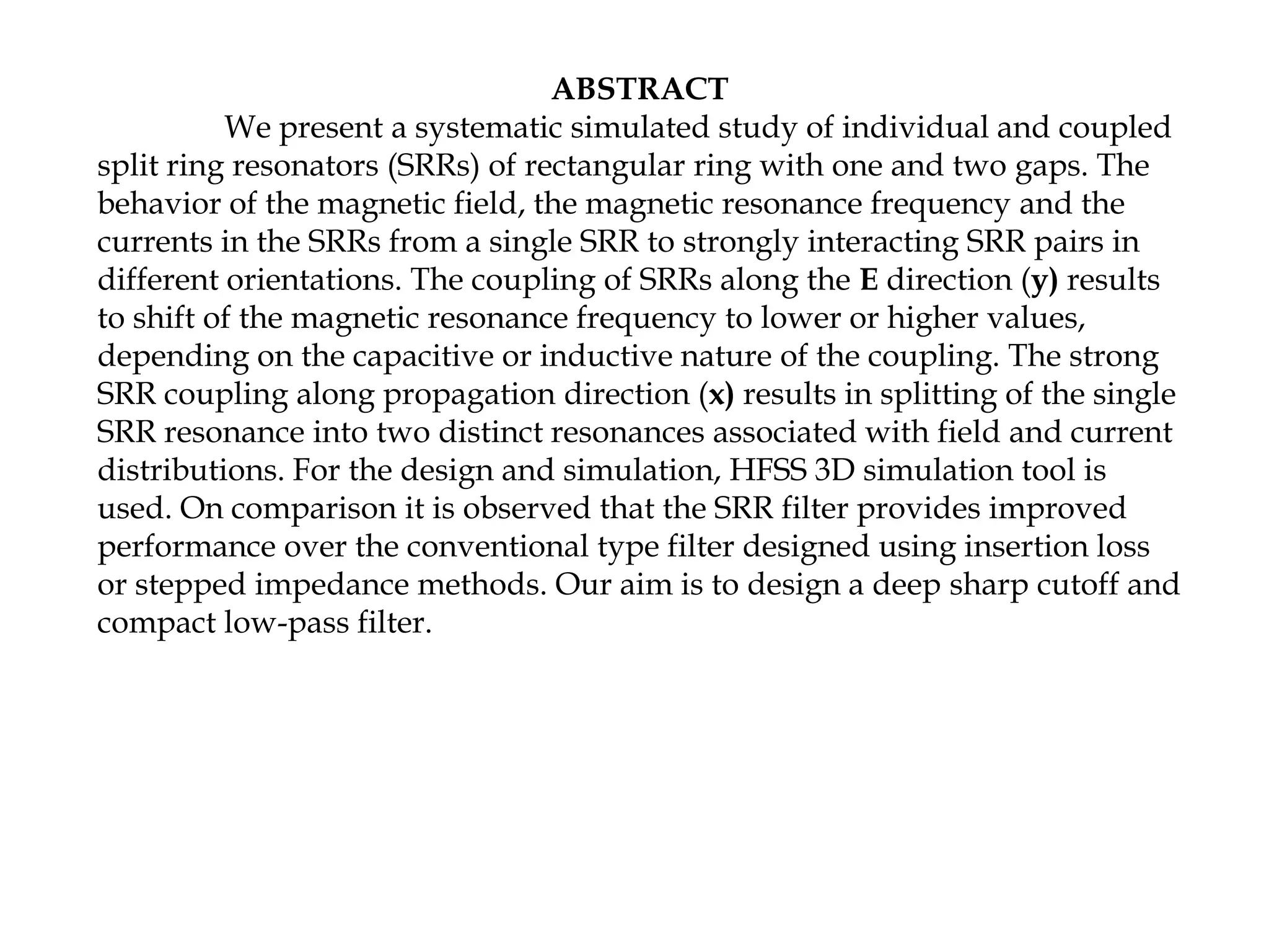
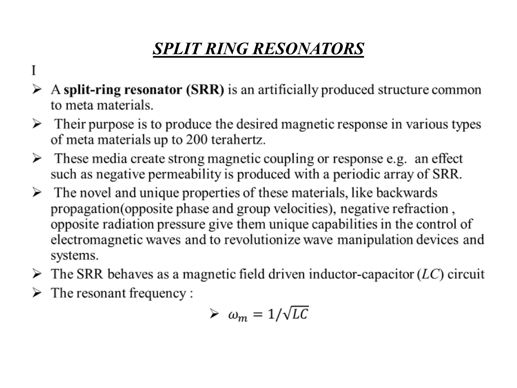
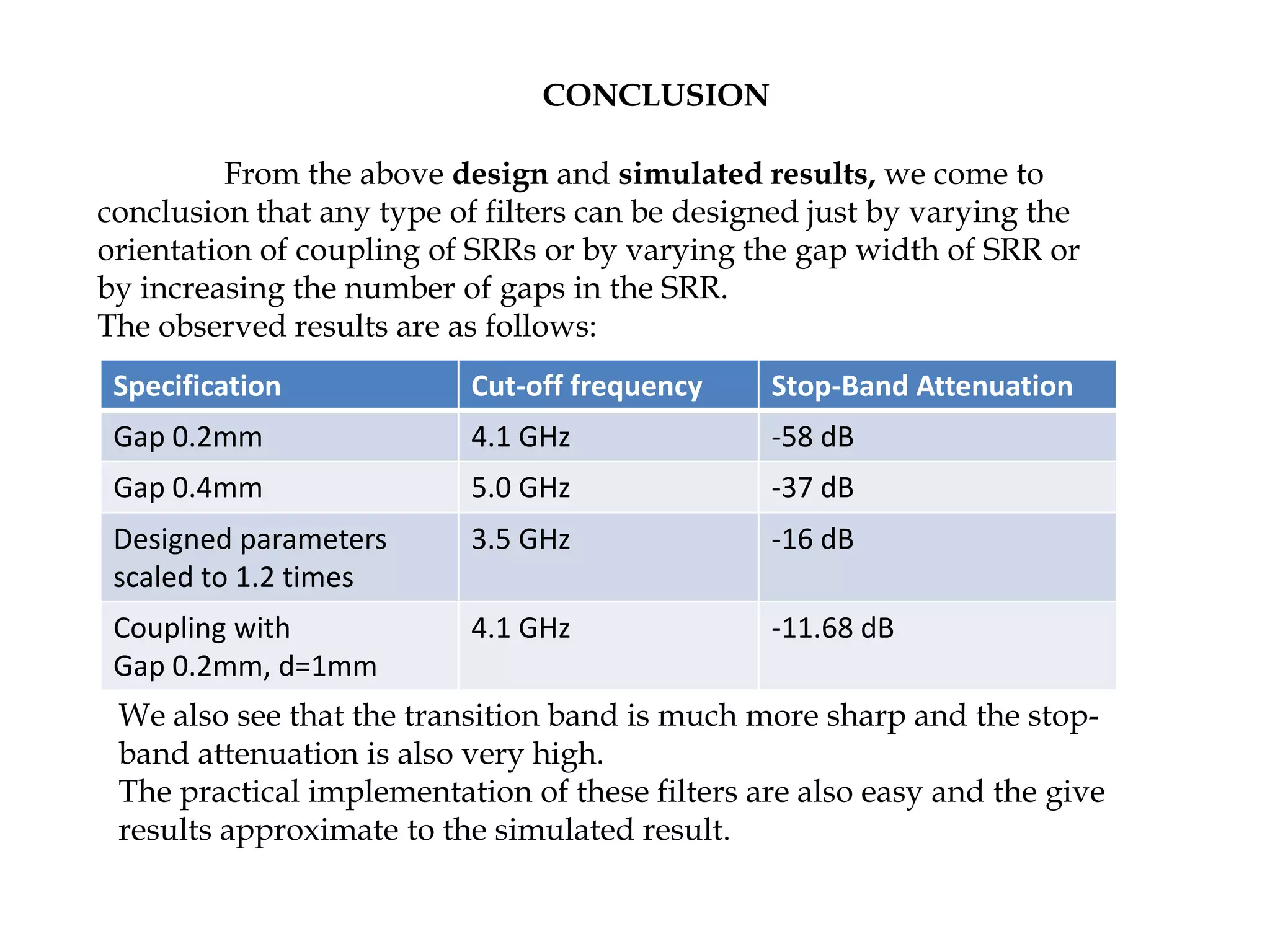
This document discusses the design and simulation of microwave resonators using split ring resonators (SRRs) and defected ground structures. It examines individual and coupled SRRs of different orientations and numbers of gaps. Simulation results using HFSS show that adjusting the SRR gap width and orientation can control the cutoff frequency and stop-band attenuation. Coupling SRRs together splits the single resonance into multiple resonances. The design achieves sharp transition bands and high stop-band attenuation, making it suitable for compact low-pass filters.
This section introduces microwave resonators, specifically split ring resonators (SRRs), their design, and application in communication filters, emphasizing compact designs and performance.
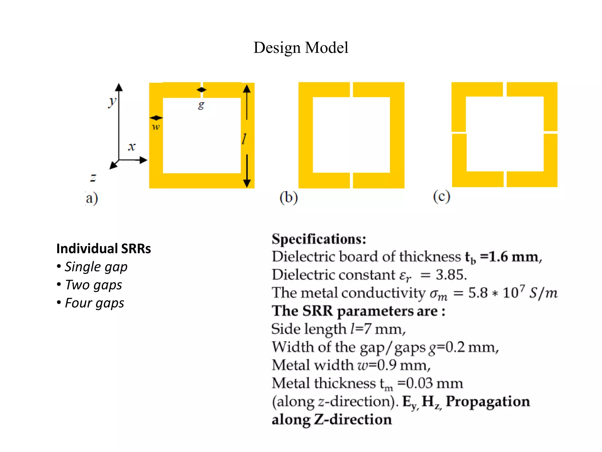
These slides detail the design model of individual SRRs, showcasing various gap configurations and their simulation results within HFSS, including output graphs and specifications.
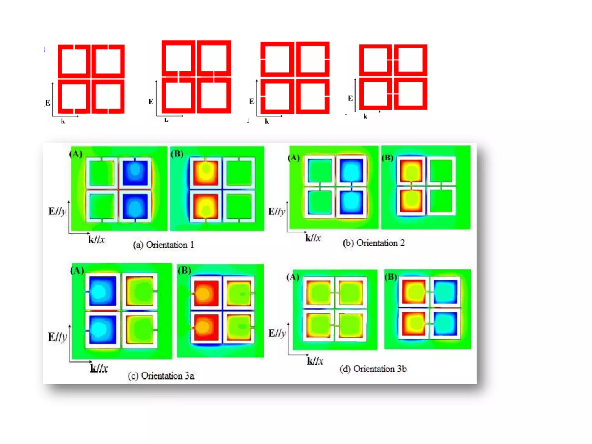
Focuses on the behavior of coupled SRRs, highlighting the effects of orientations on magnetic resonance frequency and detailing different coupling types (capacitive and inductive).
Discusses advantages of using DGS with SRR structures such as ease of implementation and tuning capabilities, followed by a conclusion summarizing design outcomes and performance metrics.
Lists reference materials used in the research, including textbooks and articles, providing additional resources for understanding microwave engineering and SRR structures.