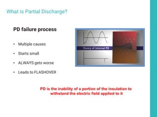
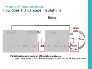
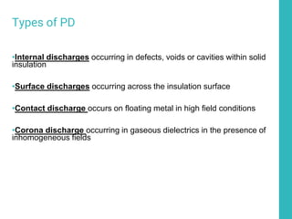
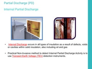
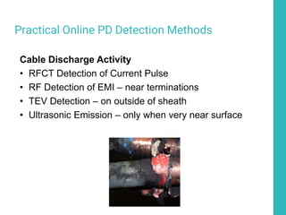
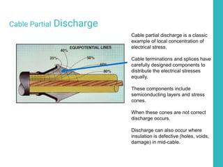
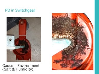
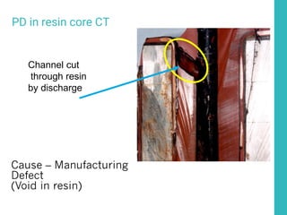
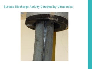
Introduction to Partial Discharge
(Causes, Effects, and Detection)
Presented by:
Tim Erwin
National Sales Manager
O 862 261 2759
C 862 222 3666
Email: Tim.erwin@eatechnologyusa.com
EA Technology History & Values
• Originally established as R&D center for the UK Electricity Industry (essentially EA
Technology was the EPRI of the UK) in the late 1960’s. Privatized in the late 1990s.
• Provides research, strategic engineering consultancy, HV asset condition assessment
services, specialized instrumentation, and Asset Management Software and Consulting.
• Instrumental in the development of PAS-55 and ISO-55000
• 100% employee owned and have provided products and service in 92 countries around the
world
EA Technology Capenhurst UK
EA Technology LLC Denville, NJ - USA
Partial Discharge – What
is it and why do we care?
6
Is Partial Discharge Real?
PD failure process
• Multiple causes
• Starts small
• ALWAYS gets worse
• Leads to FLASHOVER
What is Partial Discharge?
PD is the inability of a portion of the insulation to
withstand the electric field applied to it
Partial Discharge (PD)
The key to OUTAGE PREVENTION
•3.3kV to 769kV
•Indoor Metal clad switchgear cubicles
•Indoor and Outdoor Insulators
•Transformer Cable Boxes
•MV & HV Cables, Terminations & Underground
Vaults
•Transformers
•SF6 GIS / Oil Filled / Air Insulated
Where can it occur?
Partial Discharge - A flashover of part of the insulation system due to a
localized electric field greater than the dielectric withstand capability of that
part where the overall insulation system remains capable of withstanding
the applied electrical field.
Void
Ground
Conductor
V withstand of C2 < applied field
V withstand of C1&C3 > applied field
9
What is Partial Discharge (PD)?
One effect of this flashover is a high frequency current pulse that travels through the
capacitance of the insulation (C1 & C3)
HF Current
Pulse
C1 C2 C3
Equipotential Lines
Voltage
0 V
X kV
6X voltage
drop
Section through a homogenous insulator showing uniform electrical stress
(equipotential) lines. A line indicates where the voltage potential is constant
The same insulator with a void. The lower dielectric of the void causes
a concentration of the electrical field through the void high enough to
cause breakdown at working voltages
11
Products of Partial Discharge
Partial discharge breakdown of insulation produces:
Light, Heat, Smell, Sound, Electromagnetic Waves, and an HF
Electric Current
Electric
TEV
I
12
Products of Partial Discharge
Partial discharge breakdown of insulation produces:
Light, Heat, Smell, Sound, Electromagnetic Waves, and an HF Electric Current
+
Water
Nitric
Acid
Electric
TEV
How does PD damage insulation?
I
UK utility undertook a two year evaluation of RFCT based on-line testing that
performed a PD condition based assessment of 191 33KV cables on their
network over a two year period.
84% rated GREEN
(no problems)
>2% of those failed
within 2 years
7% rated Amber
(no problems)
<21% of those failed
within 2 years
7% rated RED
(no problems)
<40% of those failed
within 2 years
CABLE TESTING Field Example
Types of PD
•Internal discharges occurring in defects, voids or cavities within solid
insulation
•Surface discharges occurring across the insulation surface
•Contact discharge occurs on floating metal in high field conditions
•Corona discharge occurring in gaseous dielectrics in the presence of
inhomogeneous fields
• Internal Discharge occurs in all types of insulation as a result of defects, voids
or cavities within solid insulation, also including oil and gas
• Practical Non-Invasive method to detect Internal Partial Discharge Activity is to
use Transient Earth Voltage (TEV) detection instruments.
Partial Discharge (PD)
Internal Partial Discharge
• Surface discharges occurring across the insulation surface Causes
treeing and tracking
• Practical Non-Invasive method to detect Surface Partial Discharge
Activity is to use Ultrasonic Emission detection instruments.
Partial Discharge (PD)
Surface PD
Causes of PD
• Surface contamination (lack of cleaning)
• Workmanship (poor installation)
• Material defects (manufacturing defects)
• Improper application (wrong parts for the job)
• Salt spray or Salt fog
• Mechanical damage (during install or in service)
• Age (electrical stress wears out insulation)
Standards associated
with PD
IEEE 400 Series
IEEE 400 Guide to field testing shielded power cable
• Cables only
IEEE 400.1 Guide to testing shielded power cable with DC
• Not for Aged XLP cable
• Fine for PILC
• i.e.
IEEE 400.2 Guide to field testing shielded power cable with VLF
• Offline
• Time consuming
• Excellent data quality
• PD, Withstand, Tan Delta
IEEE 400.3 Guide to field PD testing of shielded power cable
• It’s a guide, not a standard!
• It does not conflict with or support IEC 60270
• It discusses online and offline testing
IEC 60270
IEC 60270 Edition 3.0, 2000
• Direct connection only
• Defines measurement circuit
• Defines measurement technique
• Defines calibration pulse generator
• Measures PD in picoColoumbs
(1 picoColoumb = 1 uA for 1 uS)
Annex D – Use of RF meters for PD detection
Annex F – Non-Electrical methods of PD detection
(Acoustic, Visual, Chemical)
IEC 60270 & IEEE 4000 test equipment
Invasive versus Non-
invasive detection
techniques
Invasive - Offline
Invasive methods require taking an outage to effect the test. Effectively this
includes all direct connected test gear
• All forms of offline testing are by definition invasive
• VLF PD cable testing requires the cable to removed from service for 3-4
hours to test
• Tan-Delta and other cable test methods require removing the cable from
service
• System Frequency PD cable testing requires getting truck mounted
equipment on site and removing the cable from service
• Permanently installed systems & sensors need to be de-energized to install
Electrical Tests Commonly Done - Offline
•High Pot (potential) Tests for ability to withstand voltage for brief periods
•Insulation Resistance (megger) Tests for resistance to ground that might
cause leakage
•Tan – Delta Tests for overall insulation health by comparing resistive and
capacitive currents
•IEEE-400 and IEC 60270 PD Tests for partial discharge offline (VLF, etc.)
Non-invasive - Online
Also known as No-Outage testing, this type of testing requires no de-
energizing of equipment and is safe to do around live voltages.
• Ultrasonic/Acoustic testing – through louvers, vents, contact sensors,
and parabolic dishes
• TEV testing – Makes use of the Transient Earth Voltage phenomenon to
safely detect internal discharge from outside cabinets
• RFCT testing* - By attaching RFCT to cable ground straps, the PD current
can be safely measured on live cables
• RF Testing – Specifically designed directional and non-directional radio
receivers can pickup the EMI generated by PD
* installing RFCT on live cables requires opening the HV compartment and appropriate safety
measures need to be followed
Practical Online PD Detection Methods
Surface Discharge Activity
• Ultrasonic Emission
• TEV Detection - when high amplitude surface
discharge
• RFCT Detection of Current Pulse
• RF Detection of EMI
Practical Online PD Detection Methods
Internal Discharge Activity
• Transient Earth Voltage (TEV) Detection
• RFCT Detection of Current Pulse
• RF Detection of EMI
Practical Online PD Detection Methods
Cable Discharge Activity
• RFCT Detection of Current Pulse
• RF Detection of EMI – near terminations
• TEV Detection – on outside of sheath
• Ultrasonic Emission – only when very near surface
Direct Connected -
Offline Testing
Very Low Frequency -
VLF
VLF (for PD)
Offline, Very Low Frequency IEC 60270 / IEEE 400.3 compliant test.
Requires an outage and cable to be disconnected on both ends.
To cable under test
To shield of cable under test
HV source
Coupling Cap
Filter
Offline PD Testing
VLF, .01-1 Hz, Resonant AC
(VLF is by far the most prevalent at medium voltage)
Cable under test
Cable Shield
Defect
AC
Voltage
Source
Filter
Coupling
Capacitor
Measuring
Instrument Measuring
Impedance
Source
Impedance
Offline PD Testing
HF Current flow due to defect flashover
Cable under test
Cable Shield
Defect
Pure
AC
Voltage
Source
Filter
Coupling
Capacitor
Measuring
Instrument Measuring
Impedance
Source
Impedance
Current pulse
A
Voltage pulses at A
Direct Connect - PDIV / PDEV
PDIV – PD Inception voltage
PDEV – PD Extinguish voltage
PDIV 16KV
PDEV 13KV
LINE 11KV
PDIV 16KV
LINE 11KV
PDEV 10KV
PD might start with a
transient but won’t continue
PD might start with a
transient but won’t stop
35
Offline Test Equipment - Test Van
Detector filter (allows LV detection lead to be connected to HV
Supply and filters Hz)
Test bushings
VLF generator
Transformer
Portable Unit -Approximately 500lbs
Direct Connected Offline
Testing – Tan Delta
Tan Delta
Tan Delta is a measurement of the loss angle or dissipation factor. Effectively,
it is measuring the ratio of the capacitance and resistance in a cable
In a perfect cable there would be no IR and
the arrow A would be straight up.
As the cable ages and gets water trees and
electrical trees, resistance through the
insulation creeps in. This causes IR and the
angle increases.
Tan Delta
Typical set up
To cable
under test
To shield
of cable
Online systems
Surface Discharge -
Ultrasonic Emission
Ultrasonic Survey
(Practical Considerations)
•Influenced by environment (e.g. temperature, humidity, pollution).
•When monitoring ultrasonically the environmental conditions (%RH
and Temperature) should also be monitored
•Discharge has a distinctive crackling noise.
•Often intermittent, particularly during early stages.
•Severity of discharge is not necessarily related to noise amplitude.
Environmental Factors
• Moisture in air will play a significant role in whether discharge is
active
• When monitoring ultrasonically the environmental conditions
(%RH and Temperature) should also be monitored
0
10
20
30
40
50
60
70
80
90
100
29/03/2005
00:00
03/04/2005
00:00
08/04/2005
00:00
13/04/2005
00:00
18/04/2005
00:00
23/04/2005
00:00
28/04/2005
00:00
03/05/2005
00:00
08/05/2005
00:00
13/05/2005
00:00
Date
%RH,
Temperature
0
1
2
3
4
5
6
7
8
9
10
Level
of
Ultrasonic
Activity
°C %RH Ultrasonic
Ultrasonic Level
Relative Humidity
< 6 Good background No observable/measurable deterioration
7 - 10
Fair
Very slight fizzing
only just above the
background
Minor Deterioration
which requires no specific action
11 - 20
Poor
Heavy fizzing or
crackling
Moderate Deterioration
Item can be returned to service.
Reinspect in 30 days.
> 20
Action Required
Spitting or sparking or
heard with the naked
ear
Serious Deterioration
Item cannot be returned to service without
shut down or engineering advise
Ultra
dB
Category Comments
Ultrasonic Interpretation
Ultrasonic Sensors
•Four different sensors are available for
ultrasonic measurements
•Built in Sensor – for general purpose
airborne ultrasonic measurements
•Flexible Sensor – for general purpose
measurements that are harder to reach
•UltraDish – Focuses sound energy for
making measurements from a greater
distance
•Contact Sensor – for making
measurements when there isn’t an air
path from the source to the sensor
Discharge noise can be picked up
Outside gear via louvers in cabinet
• Measurement relies on an air path
out of the switchgear
• Types of air paths
– Vents / Louvers
– CB Bushings / HV spouts
– Gaps around panel joints
– Bolt holes
Ultrasonic Detection
• Measurement relies on an air path
out of the switchgear
• When there’s no air path?
– Contact sensor turns panel into
sensor
– Designed to work though
cabinet metalwork, no direct air
path needed
Contact probe
Designed to work though cabinet
metalwork, no direct air path needed
Ultrasonic Detection
• Technician takes a minute or
two at each cubicle
• Listens to audio via
headphones
• Watches display for patterns
• Moves the probes along each
air gap
Ultrasonic Detection
Internal Discharge – TEV
Detection
50
Transient Earth Voltage (TEV)
Identification
•Identified over 30 years ago
•Measurement bandwidth 2 – 80 MHz
•TEV pulse rise time was found to be circa 5ns
•3dB Bandwidth = (0.35 / rise time).
•Therefore for 5ns, bandwidth = (0.35 / 5) GHz, i.e. 70 MHz
51
Internal Partial Discharge Effect 1
(Current pulse - TEV)
HV BUSBAR
PARTIAL DISCHARGE SITE
JOINT/GASKET
HV BUSBAR
HIGH FREQUENCY
PULSE TO METALWORK VIA
CAPACITANCE OF INSULATOR
TEV RESULTS DUE TO
IMPEDANCE OF GROUNDING
MEASURING
PROBE
PULSE TRAVELS
VIA SKIN EFFECT
At HF, PD currents are constrained to
flow in a thin layer on the surface of conductor.
Skin depth in mild steel at 100MHz 0.5um
52
Internal Partial Discharge Effect 2
(EM Wave)
This effect is usually less than the
current pulse unless the PD is
phase to phase!
HV BUSBAR
PARTIAL DISCHARGE SITE
JOINT/GASKET
HV BUSBAR
EM wave incident to inside surfaces
TEV RESULTS DUE TO
IMPEDANCE OF GROUNDING
MEASURING
PROBE
PULSE TRAVELS
VIA SKIN EFFECT
53
Phase to Phase Partial Discharge
(Current pulse – NO TEV)
HV BUSBAR
PARTIAL DISCHARGE
JOINT/GASKET
HV BUSBAR – Phase A
HIGH FREQUENCY
PULSE FROM PHASE TO ANOTHER.
NO CURRENT PULSE
ON METALWORK
No TEV reading
HV BUSBAR – Phase B
HV BUSBAR – Phase C
54
Phase to Phase Partial Discharge
(Current pulse – NO TEV)
HV BUSBAR
PARTIAL DISCHARGE
JOINT/GASKET
HV BUSBAR – Phase A
NO CURRENT PULSE
ON METALWORK
HV BUSBAR – Phase B
HV BUSBAR – Phase C
EM wave incident to inside surfaces
55
Partial Discharge TEV Interpretation
Probable
Internal
No Internal
Significant
Discharging
Possible
Surface Discharging
Probable
Background
Interference
Probable
Floating
Metal
Bad
Conn
• Technician takes a minute or two at
each cubicle
• Places TEV probe firmly against
panel
• Watches display for patterns
TEV Detection
PD in resin core CT
Channel cut
through resin
by discharge
Cause – Manufacturing Defect
(Void in resin)
Surface Discharge and Internal Discharge
Differences
Internal PD External PD
Not affected by Humidity Affected by Humidity
0.5-6 Pulses per Cycle 6-30 Pulses per Cycle
Rarely Audible Often Audible
Detected best by TEV Detected best by Ultrasonic
Hold UltraTEV against Ground or
Metalwork
Hold UltraTEV at airgaps of
enclosures or point UltraDish at
Elbows, T’s, or splices.
Cable Partial Discharge
Cable partial discharge is a classic
example of local concentration of
electrical stress.
Cable terminations and splices have
carefully designed components to
distribute the electrical stresses
equally.
These components include
semiconducting layers and stress
cones.
When these cones are not correct
discharge occurs.
Discharge can also occur where
insulation is defective (holes, voids,
damage) in mid-cable.
Equipotential Lines
Voltage
0 V
X kV
6X voltage
drop
Section through a homogenous insulator showing uniform electrical stress
(equipotential) lines. A line indicates where the voltage potential is constant
The same insulator with a void. The lower dielectric of the void causes
a concentration of the electrical field through the void high enough to
cause breakdown at working voltages
• RFCT placed on ground straps of
cables
• Test may do 1 or 3 phases at once
• Test may run automatically or
require operator involvement
• Different filters and triggers are
applied
• Typically less than 10 minutes to
get results
Safety First
Cable PD Detection
Shielded MV Cable
Earth
Ground
Phase
Reference
Void (PD Site)
Initial PD Current Pulse
PD causes high current pulse to
travel down shield to ground strap Instrument measures
current pulse on ground
strap
Data
Collection
RFCT based testing of cables
Cable Partial Discharge
Earth
Ground
Void (PD Site)
Reflected PD Current Pulse
Initial Pulse Reflected Pulse
Current through ground strap results from PD down cable.
Entire length of cable can be tested from one end
Far end
of cable
Termination
Ground
Strap
65
Evaluation Scale
Comments
Color
Code
XLPE
Cable
XLPE
Accessories
PILC
Cable
PILC
Accessories
Discharge within “acceptable”
limits.
0-250pC 0-500pC 0-2500pC 0-4000pC
Some concern, more frequent
monitoring recommended.
250-500pC
500-
2500pC
2500-
7000pC
4000-
10000pC
Major concern, locate PD activity
and repair or replace.
>500pC >2500pC >7000pC >10000pC
66
Cable Partial Discharge Examples
Treeing Voids / Carbonisation
Erosion from PD
Damage from flashover to screen
Cable Partial Discharge
Terrible cut line causes
electrical stress
Partial Discharge causes erosion of insulation
Stress causes partial discharge
Direct connected online
systems
On-Line systems
Direct connected online systems use permanently installed HV capacitors and
current transformers to measure PD directly.
• Periodic or 24x7 monitoring with alarming
• Typically include remote communications
• Can include humidity and load monitoring
• Can be used for Rotating machines, Metal clad switchgear, MV/HV Cables,
and Transformers
Direct connected monitoring systems
PD Couplers
72
Practical application of spot testing
Insulation
Conductor
Sheath
Earth
Ground
Ground
Straps
Data
Collection
Phase
Reference
Phase A
Phase C
Phase B
Data Analysis – VLF,
Ultrasonic, TEV, Cable
74
Analyzing Data – Two crucial pieces of data
Picking Milliamps of PD out of Kiloamps of current is not trivial.
Two key pieces of information are vital
75
Analyzing Data – Phase Resolved Plots
One sign of recognizable PD Activity is clustering of points on the
phase resolve plot at a distance of 180º apart
1 Cycle wide (16.66 ms)
Amplitude
In pC
Around 0
0
Partial Discharge tends to occur on the
rising edge of the voltage sine wave. As
such, PD impulses tend to be synchronized
to the AC waveform and 180 degrees apart.
0 90 180 270 360
Phase Resolved plots show PD impulses
on a power system cycle so groupings
180 degrees apart can be seen.
Phase resolved plots are available for TEV,
Ultrasonic, and Cable PD modes
180
Degrees
Phase Resolved Plots
77
Analyzing Data – Waveforms
A typical waveform from online Cable PD testing should have
a large unipolar pulse indicating the discharge
Very fast time base (40 uS)
Amplitude
In mA
Around 0
3,000pC
0pC
-3,000pC
0o 360o
Activity – Actual PD Phase Plot
79
Non-PD Patterns – Random Noise
Background Noise
• Below is an example of background interference, which is characterized
by random activity along the Phase Resolve plot.
• Background interference may be caused by a number of sources
including radio masts and DC light fittings.
80
Non-PD Patterns – VFD Noise
Machine Noise
• Data captured on circuits which have rotating machines operating on
them will contain some machine noise
• Machine noise is characterized by vertical lines spread across the
phase resolved plot
Partial Discharge –
Examples
A very large office building had full time partial discharge monitoring installed
due to the critical nature of its operations. The monitor had ultrasonic sensing
into each compartment from outside as shown below.
The cables to the 33VK PTs were
unshielded. They were installed
in a way that passed Highpot
testing. However, electrical field
stress was ignored
The monitor started recording
ultrasonic energy when the
humidity increased. This was
monitored for several months
before corrective action was
taken. Every cable was
damaged!
PD in unshielded cables
Ultrasonic Trends over Time
Ultrasonic reading from
top of cabinet with PD
Ultrasonic reading from
bottom of cabinet with PD
Ultrasonic reading from other
10 cabinets without PD
Note large increase in 3 months
and difference from other cabinets
Ultrasonic Trend line
PD in unshielded cables
Cause – Lack of stress control
due to poor installation
The same office building had numerous 33KV terminations. The
monitor started indicating TEV in one compartment. After several
months, Ultrasonic became apparent as well
The yellow phase termination suffered poor workmanship. It started as
internal discharge (TEV) but progressed to surface discharge as the
termination was eaten away. The final picture shows the fixed assembly
Termination – Poor workmanship
PD in Shielded Cable Terminations
Cause – Lack of stress control due to installation
errors
Surface Discharge Activity Detected by Ultrasonics
PD in Switchgear
Cause – Environment
(Salt & Humidity)
PD in resin core CT
Channel cut
through resin
by discharge
Cause – Manufacturing
Defect
(Void in resin)
Surface Discharge Activity Detected by Ultrasonics
Cable failures – Case
Studies
Cable failure example 1
Cable Type – PILC / XLPE
Voltage – 11 KV
Age – 1 Hour
Failure Location – PICAS to XLPE Branch Adapter
Cable failure example 1
Proximate Cause – Incorrect positioning of adapter tubes
Ultimate Cause – Workmanship
Takeaways
-Horrific workmanship
-Numerous future failure points present
30 mm gap in insulation Only 1 shear bolt touching No putty in shear bolts
Poorly cut tube
Cable failure example 2
Cable Type – XLPE
Voltage – 33KV
Age – 18 months
Failure Location – Joint
Cable failure example 2
Proximate Cause – Not deburring connector
Ultimate Cause – Workmanship
Takeaways
-Poor understanding of instructions
-Lack of attention to detail
-Lack of training
Furrowing not removed
Sand in joint
Sharp edge of shear bolt
Cable failure example 3
Cable Type – XLPE
Voltage – 11KV
Age – 28 years
Failure Location – Mid cable
Cable failure example 3
Proximate Cause – Moisture
Ultimate Cause – Mechanical damage to sheath
Takeaways
-Mechanical damage to otherwise good cable
-Replace waterlogged section
-Better installation practices
Trees
Electrical
Water
Cable failure example 4
Cable Type – PILC
Voltage – 11KV
Age – 47 Years
Failure Location – Mid cable
Cable failure example 4
Proximate Cause – Partial Discharge
Ultimate Cause – Age
Takeaways
- Not a bad lifespan
- Partial discharge testing would have prevented unplanned failure
- Replace Cable
Thank you
EA Technology LLC
400 Morris Avenue
Suite 240 Denville
NJ 07834
Tim Erwin
O 862 261 2759
C 862 222 3666
Email: Tim.erwin@eatechnologyusa.com
Leading Edge Sales
Jeffrey Pooranalingam
C 403 471 5799
Email: Jeffreyp@leadingedgesales.com

IEEE-Alberta_Partial-Discharge.pdf

  • 1.
    Introduction to PartialDischarge (Causes, Effects, and Detection) Presented by: Tim Erwin National Sales Manager O 862 261 2759 C 862 222 3666 Email: Tim.erwin@eatechnologyusa.com
  • 2.
    EA Technology History& Values • Originally established as R&D center for the UK Electricity Industry (essentially EA Technology was the EPRI of the UK) in the late 1960’s. Privatized in the late 1990s. • Provides research, strategic engineering consultancy, HV asset condition assessment services, specialized instrumentation, and Asset Management Software and Consulting. • Instrumental in the development of PAS-55 and ISO-55000 • 100% employee owned and have provided products and service in 92 countries around the world EA Technology Capenhurst UK EA Technology LLC Denville, NJ - USA
  • 3.
    Partial Discharge –What is it and why do we care?
  • 4.
  • 5.
    PD failure process •Multiple causes • Starts small • ALWAYS gets worse • Leads to FLASHOVER What is Partial Discharge? PD is the inability of a portion of the insulation to withstand the electric field applied to it
  • 6.
    Partial Discharge (PD) Thekey to OUTAGE PREVENTION •3.3kV to 769kV •Indoor Metal clad switchgear cubicles •Indoor and Outdoor Insulators •Transformer Cable Boxes •MV & HV Cables, Terminations & Underground Vaults •Transformers •SF6 GIS / Oil Filled / Air Insulated Where can it occur?
  • 7.
    Partial Discharge -A flashover of part of the insulation system due to a localized electric field greater than the dielectric withstand capability of that part where the overall insulation system remains capable of withstanding the applied electrical field. Void Ground Conductor V withstand of C2 < applied field V withstand of C1&C3 > applied field 9 What is Partial Discharge (PD)? One effect of this flashover is a high frequency current pulse that travels through the capacitance of the insulation (C1 & C3) HF Current Pulse C1 C2 C3
  • 8.
    Equipotential Lines Voltage 0 V XkV 6X voltage drop Section through a homogenous insulator showing uniform electrical stress (equipotential) lines. A line indicates where the voltage potential is constant The same insulator with a void. The lower dielectric of the void causes a concentration of the electrical field through the void high enough to cause breakdown at working voltages
  • 9.
    11 Products of PartialDischarge Partial discharge breakdown of insulation produces: Light, Heat, Smell, Sound, Electromagnetic Waves, and an HF Electric Current Electric TEV I
  • 10.
    12 Products of PartialDischarge Partial discharge breakdown of insulation produces: Light, Heat, Smell, Sound, Electromagnetic Waves, and an HF Electric Current + Water Nitric Acid Electric TEV How does PD damage insulation? I
  • 11.
    UK utility undertooka two year evaluation of RFCT based on-line testing that performed a PD condition based assessment of 191 33KV cables on their network over a two year period. 84% rated GREEN (no problems) >2% of those failed within 2 years 7% rated Amber (no problems) <21% of those failed within 2 years 7% rated RED (no problems) <40% of those failed within 2 years CABLE TESTING Field Example
  • 12.
    Types of PD •Internaldischarges occurring in defects, voids or cavities within solid insulation •Surface discharges occurring across the insulation surface •Contact discharge occurs on floating metal in high field conditions •Corona discharge occurring in gaseous dielectrics in the presence of inhomogeneous fields
  • 13.
    • Internal Dischargeoccurs in all types of insulation as a result of defects, voids or cavities within solid insulation, also including oil and gas • Practical Non-Invasive method to detect Internal Partial Discharge Activity is to use Transient Earth Voltage (TEV) detection instruments. Partial Discharge (PD) Internal Partial Discharge
  • 14.
    • Surface dischargesoccurring across the insulation surface Causes treeing and tracking • Practical Non-Invasive method to detect Surface Partial Discharge Activity is to use Ultrasonic Emission detection instruments. Partial Discharge (PD) Surface PD
  • 15.
    Causes of PD •Surface contamination (lack of cleaning) • Workmanship (poor installation) • Material defects (manufacturing defects) • Improper application (wrong parts for the job) • Salt spray or Salt fog • Mechanical damage (during install or in service) • Age (electrical stress wears out insulation)
  • 16.
  • 17.
    IEEE 400 Series IEEE400 Guide to field testing shielded power cable • Cables only IEEE 400.1 Guide to testing shielded power cable with DC • Not for Aged XLP cable • Fine for PILC • i.e. IEEE 400.2 Guide to field testing shielded power cable with VLF • Offline • Time consuming • Excellent data quality • PD, Withstand, Tan Delta IEEE 400.3 Guide to field PD testing of shielded power cable • It’s a guide, not a standard! • It does not conflict with or support IEC 60270 • It discusses online and offline testing
  • 18.
    IEC 60270 IEC 60270Edition 3.0, 2000 • Direct connection only • Defines measurement circuit • Defines measurement technique • Defines calibration pulse generator • Measures PD in picoColoumbs (1 picoColoumb = 1 uA for 1 uS) Annex D – Use of RF meters for PD detection Annex F – Non-Electrical methods of PD detection (Acoustic, Visual, Chemical)
  • 19.
    IEC 60270 &IEEE 4000 test equipment
  • 20.
    Invasive versus Non- invasivedetection techniques
  • 21.
    Invasive - Offline Invasivemethods require taking an outage to effect the test. Effectively this includes all direct connected test gear • All forms of offline testing are by definition invasive • VLF PD cable testing requires the cable to removed from service for 3-4 hours to test • Tan-Delta and other cable test methods require removing the cable from service • System Frequency PD cable testing requires getting truck mounted equipment on site and removing the cable from service • Permanently installed systems & sensors need to be de-energized to install
  • 22.
    Electrical Tests CommonlyDone - Offline •High Pot (potential) Tests for ability to withstand voltage for brief periods •Insulation Resistance (megger) Tests for resistance to ground that might cause leakage •Tan – Delta Tests for overall insulation health by comparing resistive and capacitive currents •IEEE-400 and IEC 60270 PD Tests for partial discharge offline (VLF, etc.)
  • 23.
    Non-invasive - Online Alsoknown as No-Outage testing, this type of testing requires no de- energizing of equipment and is safe to do around live voltages. • Ultrasonic/Acoustic testing – through louvers, vents, contact sensors, and parabolic dishes • TEV testing – Makes use of the Transient Earth Voltage phenomenon to safely detect internal discharge from outside cabinets • RFCT testing* - By attaching RFCT to cable ground straps, the PD current can be safely measured on live cables • RF Testing – Specifically designed directional and non-directional radio receivers can pickup the EMI generated by PD * installing RFCT on live cables requires opening the HV compartment and appropriate safety measures need to be followed
  • 24.
    Practical Online PDDetection Methods Surface Discharge Activity • Ultrasonic Emission • TEV Detection - when high amplitude surface discharge • RFCT Detection of Current Pulse • RF Detection of EMI
  • 25.
    Practical Online PDDetection Methods Internal Discharge Activity • Transient Earth Voltage (TEV) Detection • RFCT Detection of Current Pulse • RF Detection of EMI
  • 26.
    Practical Online PDDetection Methods Cable Discharge Activity • RFCT Detection of Current Pulse • RF Detection of EMI – near terminations • TEV Detection – on outside of sheath • Ultrasonic Emission – only when very near surface
  • 27.
  • 28.
  • 29.
    VLF (for PD) Offline,Very Low Frequency IEC 60270 / IEEE 400.3 compliant test. Requires an outage and cable to be disconnected on both ends. To cable under test To shield of cable under test HV source Coupling Cap Filter
  • 30.
    Offline PD Testing VLF,.01-1 Hz, Resonant AC (VLF is by far the most prevalent at medium voltage) Cable under test Cable Shield Defect AC Voltage Source Filter Coupling Capacitor Measuring Instrument Measuring Impedance Source Impedance
  • 31.
    Offline PD Testing HFCurrent flow due to defect flashover Cable under test Cable Shield Defect Pure AC Voltage Source Filter Coupling Capacitor Measuring Instrument Measuring Impedance Source Impedance Current pulse A Voltage pulses at A
  • 32.
    Direct Connect -PDIV / PDEV PDIV – PD Inception voltage PDEV – PD Extinguish voltage PDIV 16KV PDEV 13KV LINE 11KV PDIV 16KV LINE 11KV PDEV 10KV PD might start with a transient but won’t continue PD might start with a transient but won’t stop
  • 33.
    35 Offline Test Equipment- Test Van Detector filter (allows LV detection lead to be connected to HV Supply and filters Hz) Test bushings VLF generator Transformer
  • 34.
  • 35.
  • 36.
    Tan Delta Tan Deltais a measurement of the loss angle or dissipation factor. Effectively, it is measuring the ratio of the capacitance and resistance in a cable In a perfect cable there would be no IR and the arrow A would be straight up. As the cable ages and gets water trees and electrical trees, resistance through the insulation creeps in. This causes IR and the angle increases.
  • 37.
    Tan Delta Typical setup To cable under test To shield of cable
  • 38.
  • 39.
  • 40.
    Ultrasonic Survey (Practical Considerations) •Influencedby environment (e.g. temperature, humidity, pollution). •When monitoring ultrasonically the environmental conditions (%RH and Temperature) should also be monitored •Discharge has a distinctive crackling noise. •Often intermittent, particularly during early stages. •Severity of discharge is not necessarily related to noise amplitude.
  • 41.
    Environmental Factors • Moisturein air will play a significant role in whether discharge is active • When monitoring ultrasonically the environmental conditions (%RH and Temperature) should also be monitored 0 10 20 30 40 50 60 70 80 90 100 29/03/2005 00:00 03/04/2005 00:00 08/04/2005 00:00 13/04/2005 00:00 18/04/2005 00:00 23/04/2005 00:00 28/04/2005 00:00 03/05/2005 00:00 08/05/2005 00:00 13/05/2005 00:00 Date %RH, Temperature 0 1 2 3 4 5 6 7 8 9 10 Level of Ultrasonic Activity °C %RH Ultrasonic Ultrasonic Level Relative Humidity
  • 42.
    < 6 Goodbackground No observable/measurable deterioration 7 - 10 Fair Very slight fizzing only just above the background Minor Deterioration which requires no specific action 11 - 20 Poor Heavy fizzing or crackling Moderate Deterioration Item can be returned to service. Reinspect in 30 days. > 20 Action Required Spitting or sparking or heard with the naked ear Serious Deterioration Item cannot be returned to service without shut down or engineering advise Ultra dB Category Comments Ultrasonic Interpretation
  • 43.
    Ultrasonic Sensors •Four differentsensors are available for ultrasonic measurements •Built in Sensor – for general purpose airborne ultrasonic measurements •Flexible Sensor – for general purpose measurements that are harder to reach •UltraDish – Focuses sound energy for making measurements from a greater distance •Contact Sensor – for making measurements when there isn’t an air path from the source to the sensor
  • 44.
    Discharge noise canbe picked up Outside gear via louvers in cabinet • Measurement relies on an air path out of the switchgear • Types of air paths – Vents / Louvers – CB Bushings / HV spouts – Gaps around panel joints – Bolt holes Ultrasonic Detection
  • 45.
    • Measurement relieson an air path out of the switchgear • When there’s no air path? – Contact sensor turns panel into sensor – Designed to work though cabinet metalwork, no direct air path needed Contact probe Designed to work though cabinet metalwork, no direct air path needed Ultrasonic Detection
  • 46.
    • Technician takesa minute or two at each cubicle • Listens to audio via headphones • Watches display for patterns • Moves the probes along each air gap Ultrasonic Detection
  • 47.
  • 48.
    50 Transient Earth Voltage(TEV) Identification •Identified over 30 years ago •Measurement bandwidth 2 – 80 MHz •TEV pulse rise time was found to be circa 5ns •3dB Bandwidth = (0.35 / rise time). •Therefore for 5ns, bandwidth = (0.35 / 5) GHz, i.e. 70 MHz
  • 49.
    51 Internal Partial DischargeEffect 1 (Current pulse - TEV) HV BUSBAR PARTIAL DISCHARGE SITE JOINT/GASKET HV BUSBAR HIGH FREQUENCY PULSE TO METALWORK VIA CAPACITANCE OF INSULATOR TEV RESULTS DUE TO IMPEDANCE OF GROUNDING MEASURING PROBE PULSE TRAVELS VIA SKIN EFFECT At HF, PD currents are constrained to flow in a thin layer on the surface of conductor. Skin depth in mild steel at 100MHz 0.5um
  • 50.
    52 Internal Partial DischargeEffect 2 (EM Wave) This effect is usually less than the current pulse unless the PD is phase to phase! HV BUSBAR PARTIAL DISCHARGE SITE JOINT/GASKET HV BUSBAR EM wave incident to inside surfaces TEV RESULTS DUE TO IMPEDANCE OF GROUNDING MEASURING PROBE PULSE TRAVELS VIA SKIN EFFECT
  • 51.
    53 Phase to PhasePartial Discharge (Current pulse – NO TEV) HV BUSBAR PARTIAL DISCHARGE JOINT/GASKET HV BUSBAR – Phase A HIGH FREQUENCY PULSE FROM PHASE TO ANOTHER. NO CURRENT PULSE ON METALWORK No TEV reading HV BUSBAR – Phase B HV BUSBAR – Phase C
  • 52.
    54 Phase to PhasePartial Discharge (Current pulse – NO TEV) HV BUSBAR PARTIAL DISCHARGE JOINT/GASKET HV BUSBAR – Phase A NO CURRENT PULSE ON METALWORK HV BUSBAR – Phase B HV BUSBAR – Phase C EM wave incident to inside surfaces
  • 53.
    55 Partial Discharge TEVInterpretation Probable Internal No Internal Significant Discharging Possible Surface Discharging Probable Background Interference Probable Floating Metal Bad Conn
  • 54.
    • Technician takesa minute or two at each cubicle • Places TEV probe firmly against panel • Watches display for patterns TEV Detection
  • 55.
    PD in resincore CT Channel cut through resin by discharge Cause – Manufacturing Defect (Void in resin)
  • 56.
    Surface Discharge andInternal Discharge Differences Internal PD External PD Not affected by Humidity Affected by Humidity 0.5-6 Pulses per Cycle 6-30 Pulses per Cycle Rarely Audible Often Audible Detected best by TEV Detected best by Ultrasonic Hold UltraTEV against Ground or Metalwork Hold UltraTEV at airgaps of enclosures or point UltraDish at Elbows, T’s, or splices.
  • 57.
  • 58.
    Cable Partial Discharge Cablepartial discharge is a classic example of local concentration of electrical stress. Cable terminations and splices have carefully designed components to distribute the electrical stresses equally. These components include semiconducting layers and stress cones. When these cones are not correct discharge occurs. Discharge can also occur where insulation is defective (holes, voids, damage) in mid-cable.
  • 59.
    Equipotential Lines Voltage 0 V XkV 6X voltage drop Section through a homogenous insulator showing uniform electrical stress (equipotential) lines. A line indicates where the voltage potential is constant The same insulator with a void. The lower dielectric of the void causes a concentration of the electrical field through the void high enough to cause breakdown at working voltages
  • 60.
    • RFCT placedon ground straps of cables • Test may do 1 or 3 phases at once • Test may run automatically or require operator involvement • Different filters and triggers are applied • Typically less than 10 minutes to get results Safety First Cable PD Detection
  • 61.
    Shielded MV Cable Earth Ground Phase Reference Void(PD Site) Initial PD Current Pulse PD causes high current pulse to travel down shield to ground strap Instrument measures current pulse on ground strap Data Collection RFCT based testing of cables
  • 62.
    Cable Partial Discharge Earth Ground Void(PD Site) Reflected PD Current Pulse Initial Pulse Reflected Pulse Current through ground strap results from PD down cable. Entire length of cable can be tested from one end Far end of cable Termination Ground Strap
  • 63.
    65 Evaluation Scale Comments Color Code XLPE Cable XLPE Accessories PILC Cable PILC Accessories Discharge within“acceptable” limits. 0-250pC 0-500pC 0-2500pC 0-4000pC Some concern, more frequent monitoring recommended. 250-500pC 500- 2500pC 2500- 7000pC 4000- 10000pC Major concern, locate PD activity and repair or replace. >500pC >2500pC >7000pC >10000pC
  • 64.
    66 Cable Partial DischargeExamples Treeing Voids / Carbonisation Erosion from PD Damage from flashover to screen
  • 65.
    Cable Partial Discharge Terriblecut line causes electrical stress Partial Discharge causes erosion of insulation Stress causes partial discharge
  • 66.
  • 67.
    On-Line systems Direct connectedonline systems use permanently installed HV capacitors and current transformers to measure PD directly. • Periodic or 24x7 monitoring with alarming • Typically include remote communications • Can include humidity and load monitoring • Can be used for Rotating machines, Metal clad switchgear, MV/HV Cables, and Transformers
  • 68.
  • 69.
  • 70.
    72 Practical application ofspot testing Insulation Conductor Sheath Earth Ground Ground Straps Data Collection Phase Reference Phase A Phase C Phase B
  • 71.
    Data Analysis –VLF, Ultrasonic, TEV, Cable
  • 72.
    74 Analyzing Data –Two crucial pieces of data Picking Milliamps of PD out of Kiloamps of current is not trivial. Two key pieces of information are vital
  • 73.
    75 Analyzing Data –Phase Resolved Plots One sign of recognizable PD Activity is clustering of points on the phase resolve plot at a distance of 180º apart 1 Cycle wide (16.66 ms) Amplitude In pC Around 0 0
  • 74.
    Partial Discharge tendsto occur on the rising edge of the voltage sine wave. As such, PD impulses tend to be synchronized to the AC waveform and 180 degrees apart. 0 90 180 270 360 Phase Resolved plots show PD impulses on a power system cycle so groupings 180 degrees apart can be seen. Phase resolved plots are available for TEV, Ultrasonic, and Cable PD modes 180 Degrees Phase Resolved Plots
  • 75.
    77 Analyzing Data –Waveforms A typical waveform from online Cable PD testing should have a large unipolar pulse indicating the discharge Very fast time base (40 uS) Amplitude In mA Around 0
  • 76.
  • 77.
    79 Non-PD Patterns –Random Noise Background Noise • Below is an example of background interference, which is characterized by random activity along the Phase Resolve plot. • Background interference may be caused by a number of sources including radio masts and DC light fittings.
  • 78.
    80 Non-PD Patterns –VFD Noise Machine Noise • Data captured on circuits which have rotating machines operating on them will contain some machine noise • Machine noise is characterized by vertical lines spread across the phase resolved plot
  • 79.
  • 80.
    A very largeoffice building had full time partial discharge monitoring installed due to the critical nature of its operations. The monitor had ultrasonic sensing into each compartment from outside as shown below. The cables to the 33VK PTs were unshielded. They were installed in a way that passed Highpot testing. However, electrical field stress was ignored The monitor started recording ultrasonic energy when the humidity increased. This was monitored for several months before corrective action was taken. Every cable was damaged! PD in unshielded cables
  • 81.
    Ultrasonic Trends overTime Ultrasonic reading from top of cabinet with PD Ultrasonic reading from bottom of cabinet with PD Ultrasonic reading from other 10 cabinets without PD Note large increase in 3 months and difference from other cabinets Ultrasonic Trend line
  • 82.
    PD in unshieldedcables Cause – Lack of stress control due to poor installation
  • 83.
    The same officebuilding had numerous 33KV terminations. The monitor started indicating TEV in one compartment. After several months, Ultrasonic became apparent as well The yellow phase termination suffered poor workmanship. It started as internal discharge (TEV) but progressed to surface discharge as the termination was eaten away. The final picture shows the fixed assembly Termination – Poor workmanship
  • 84.
    PD in ShieldedCable Terminations Cause – Lack of stress control due to installation errors
  • 85.
    Surface Discharge ActivityDetected by Ultrasonics
  • 86.
    PD in Switchgear Cause– Environment (Salt & Humidity)
  • 87.
    PD in resincore CT Channel cut through resin by discharge Cause – Manufacturing Defect (Void in resin)
  • 88.
    Surface Discharge ActivityDetected by Ultrasonics
  • 89.
    Cable failures –Case Studies
  • 90.
    Cable failure example1 Cable Type – PILC / XLPE Voltage – 11 KV Age – 1 Hour Failure Location – PICAS to XLPE Branch Adapter
  • 91.
    Cable failure example1 Proximate Cause – Incorrect positioning of adapter tubes Ultimate Cause – Workmanship Takeaways -Horrific workmanship -Numerous future failure points present 30 mm gap in insulation Only 1 shear bolt touching No putty in shear bolts Poorly cut tube
  • 92.
    Cable failure example2 Cable Type – XLPE Voltage – 33KV Age – 18 months Failure Location – Joint
  • 93.
    Cable failure example2 Proximate Cause – Not deburring connector Ultimate Cause – Workmanship Takeaways -Poor understanding of instructions -Lack of attention to detail -Lack of training Furrowing not removed Sand in joint Sharp edge of shear bolt
  • 94.
    Cable failure example3 Cable Type – XLPE Voltage – 11KV Age – 28 years Failure Location – Mid cable
  • 95.
    Cable failure example3 Proximate Cause – Moisture Ultimate Cause – Mechanical damage to sheath Takeaways -Mechanical damage to otherwise good cable -Replace waterlogged section -Better installation practices Trees Electrical Water
  • 96.
    Cable failure example4 Cable Type – PILC Voltage – 11KV Age – 47 Years Failure Location – Mid cable
  • 97.
    Cable failure example4 Proximate Cause – Partial Discharge Ultimate Cause – Age Takeaways - Not a bad lifespan - Partial discharge testing would have prevented unplanned failure - Replace Cable
  • 98.
    Thank you EA TechnologyLLC 400 Morris Avenue Suite 240 Denville NJ 07834 Tim Erwin O 862 261 2759 C 862 222 3666 Email: Tim.erwin@eatechnologyusa.com Leading Edge Sales Jeffrey Pooranalingam C 403 471 5799 Email: Jeffreyp@leadingedgesales.com