Downloaded 429 times

![8
Hysteresis
It refers to the difference
between upscale sequence
of calibration and downscale
sequence of calibration
he=({y}upscale-{y}downscale)x=x1
Hysteresis error = [he(max)/FSOR] ×100
FSOR : Full Scale Output Reading
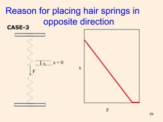
Fig. Internal force verses extension
of a rubber band follows
hysteresis. External force is in
opposition to internal force
E.g. Potentiometer used as
displacement sensor with
significant losses](https://image.slidesharecdn.com/1-170114040648/85/Electrical-Measurement-Instruments-8-320.jpg)

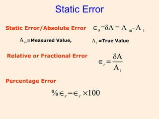
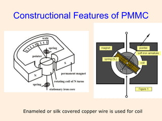
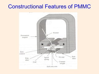
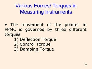
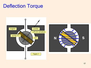
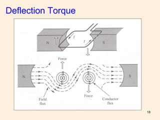
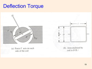
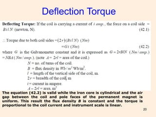
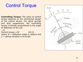
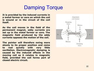

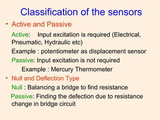
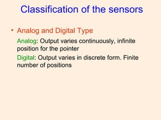
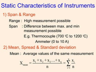
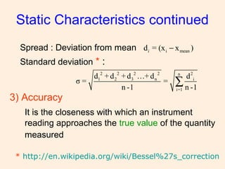
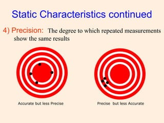
The document categorizes sensors into active and passive types, as well as analog and digital types, detailing their characteristics and measurement principles. It discusses static characteristics of instruments, including range, accuracy, precision, resolution, and sensitivity, alongside various types of errors encountered in measurements. Additionally, it describes the mechanisms of electromechanical indicating instruments, focusing on permanent magnet moving coil (PMMC) instruments and their operational features such as deflection, control, and damping torques.


![ELECTRICAL MEASUREMENT & MEASURING INSTRUMENTS [Emmi- (NEE-302) -unit-1]](https://cdn.slidesharecdn.com/ss_thumbnails/emmi-nee-302-unit-1-170607090405-thumbnail.jpg?width=640&height=640&fit=bounds)


