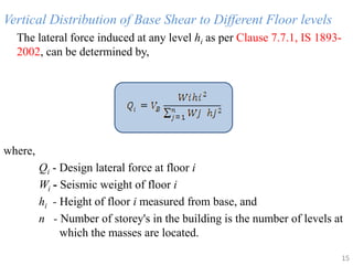
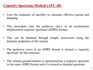
SlideShare a Scribd company logo
1 of 58
Download to read offline
SEISMIC ANALYSIS OF
RC BUILDINGS
1
INTRODUCTION
• Since earthquake forces are random in nature and
unpredictable, the static and dynamic analysis of the
structures have become the primary concern of civil
engineers.
• The main parameters of the seismic analysis of
structures are load carrying capacity, ductility,
stiffness, damping and mass.
• IS 1893-2002 is used to carryout the seismic analysis
of multi-storey building. 2
SEISMIC ANALYSIS OF STRUCTURES
• The seismic analysis type that should be used to
analyse the structure depends upon :-
 external action
 the behavior of structure or structural
materials
 the type of structural model selected
3
• The different analysis procedure are
 Linear Static Analysis
 Nonlinear Static Analysis
 Linear Dynamic Analysis
 Nonlinear Dynamic Analysis
4
LINEAR STATIC ANALYSIS
5
• Also known as Equivalent Static method.
• Based on formulas given in the code of practice.
STEPS
• First, the design base shear is computed for the whole building.
• It is then distributed along the height of the building.
• The lateral forces at each floor levels thus obtained are distributed
to individual lateral load resisting elements.
6
7
Equivalent lateral shear force along two orthogonal axis
(Source: Nouredine Bourahla, "Equivalent Static Analysis of Structures Subjected to
Seismic Actions", Encyclopedia of Earthquake Engineering, Springer-Verlag Berlin
Heidelberg, 2013)
8
Limitations
The use of this method is restricted with respect to
• High seismic zones and height of the structure
• Buildings having higher modes of vibration than the
fundamental mode
• Structures having significant discontinuities in mass and
stiffness along the height
PROCEDURE
• Calculation of the Design Seismic Base Shear, VB
• Vertical distribution of base shear along the height of
the structure
• Horizontal distribution of the level forces across the
width and breadth of the structure
• Determination of the drift, overturning moment, and
P-Delta effect
9
Design Seismic Base Shear, VB
From IS 1893- 2002, Clause 7.5.3, the design base shear
where,
W - seismic weight of the building
Ah - horizontal seismic coefficient
Horizontal Seismic Coefficient, Ah
As per IS 1893(Part 1)-2002, Clause 6.4.2
Provided that for any structure with T < 0.1 s, the value of Ah will not be taken less
than Z/2 whatever be the value of I/R.
10
Ah =
VB= Ah W
Where,
Z - Zone factor
I - Importance factor
R- Response Reduction factor
Sa/g - Average response acceleration coefficient
T -Undamped Natural period of the structure
11
Zone Factor ( Z)
• It is the indicator of the maximum seismic risk characterized by
Maximum Considered Earthquake (MCE ) in the zone in which the
structure is located.
• According to IS 1893(Part 1)-2002, Seismic Zones are classified into
II, III, IV & V respectively.
Average response acceleration coefficient (Sa/g)
• It depends on the type of rock or soil sites and also the natural period
and damping of the structure.
• It is obtained from, Clause 6.4.5, IS 1893-2002.
12
Importance Factor (I)
• It depends on the occupancy category of the building.
• It is obtained from table 6, Clause 6.4.2, IS 1893-2002.
Site Class
• Site Class is determined based on the average properties of the soil within a
certain depth (30 m) from the ground surface.
Response Reduction factor (R)
• It is determined by the type of lateral load resisting system used.
• It is a measure of the system’s ability to accommodate earthquake loads and
absorb energy without collapse.
• It is obtained from table 7, IS 1893-2002.
13
Ta =
Fundamental Period
• The approximate fundamental natural period of vibration ( Ta ),
of a MRF building from Clause 7.6,
without brick infil panels,
with infil panels,
14
where,
h - height of the building
d- Base dimension of the building at the plinth level
Ta = 0.075 h0.75 for RC frame building
= 0.085 h0.75 for steel frame building
Vertical Distribution of Base Shear to Different Floor levels
The lateral force induced at any level hi as per Clause 7.7.1, IS 1893-
2002, can be determined by,
where,
Qi - Design lateral force at floor i
Wi - Seismic weight of floor i
hi - Height of floor i measured from base, and
n - Number of storey's in the building is the number of levels at
which the masses are located.
15
Horizontal Distribution of Base Shear
The horizontal distribution of base shear as per FEMA P749, can be
determined by
where,
Fij : force acting on the lateral force-resisting line j at a floor level i
nk : number of lateral force-resisting elements (lines)
Kij ,Kik : story stiffness of the lateral force-resisting element (line) k
and j at level i
Fi : seismic force at floor (level) i
16
Drift Story
• It is a measure of how much one floor or roof level displaces under
the lateral force relative to the floor level immediately below.
• It is the ratio of the difference in deflection between two adjacent
floors divided by the height of the story that separates the floors.
Overturning Moment and P-Delta Effects
• There is a tendency for the moment created by equivalent static
force acting above the base to overturn the structure.
• The dead weight of the building is sufficient to resist the overturning
force, but it must be checked always.
17
• The “stability coefficient” for each story as per FEMA P749, can
be calculated as,
where,
Pi - weight of the structure above the story being evaluated
i - is the design story drift determined
Vi - is the sum of the lateral seismic design forces above the story
hi - story height
18
=
NONLINEAR STATIC ANALYSIS
19
• Also known as Pushover Analysis
• Used to estimate the strength and drift capacity of existing
structure and the seismic demand for this structure subjected to
selected earthquake.
• It can be used for checking the adequacy of new structural
design as well.
• It is an analysis in which, a mathematical model incorporates
the nonlinear load-deformation characteristics of individual
components and elements of the building which shall be
subjected to increasing lateral loads representing inertia forces
in an earthquake until a ‘target displacement’ is exceeded.
20
• Response characteristics that can be obtained from the pushover
analysis are
– Estimates of force and displacement capacities of the structure.
– Sequences of the failure of elements and the consequent effect
on the overall structural stability.
– Identification of the critical regions, where the inelastic
deformations are expected to be high and identification of
strength irregularities of the building.
21
PROCEDURE
 In Pushover analysis the magnitude of the lateral load is
increased monotonically maintaining a predefined distribution
pattern along the height of the building.
 Building is displaced till the ‘control node’ reaches ‘target
displacement’ or building collapses.
 The sequence of cracking, plastic hinging and failure of the
structural components throughout the procedure is observed.
 The relation between base shear and control node
displacement is plotted for all the pushover analysis.
22
23
Schematic representation of pushover analysis procedure
(Source: Jan, T.S.; Liu, M.W. and Kao, Y.C. (2004), “An
upper-bond pushover analysis procedure for estimating
the seismic demands of high-rise buildings”. Engineering
structures. 117-128)
• Pushover analysis may be carried out twice:
(a) first time till the collapse of the building to estimate target
displacement.
(b) next time till the target displacement to estimate the seismic
demand.
• The seismic demands for the selected earthquake are calculated at
the target displacement level.
• The seismic demand is then compared with the corresponding
structural capacity to know what performance the structure will
exhibit.
24
Lateral Load Patterns
 FEMA 356 suggests the use of at least two different patterns for
all pushover analysis.
Group – I
i) Code-based vertical distribution of lateral forces used in
equivalent static analysis
ii) A vertical distribution proportional to the shape of the
fundamental mode in the direction under consideration
iii) A vertical distribution proportional to the story shear
distribution calculated by combining modal responses from a
response spectrum analysis of the building
25
Group – II
i) A uniform distribution consisting of lateral forces at each level proportional to the
total mass at each level
ii) An adaptive load distribution that changes as the structure is displaced
26
Lateral load pattern for pushover analysis as per FEMA 356
(Source: Jan, T.S.; Liu, M.W. and Kao, Y.C. (2004), “An upper-bond
pushover analysis procedure for estimating the seismic demands of high-
rise buildings”. Engineering structures. 117-128)
Target Displacement
Two approaches to calculate target displacement:
(a) Displacement Coefficient Method (DCM) of FEMA 356
(b) Capacity Spectrum Method (CSM) of ATC 40
• Both of these approaches use pushover curve to calculate global
displacement demand on the building.
• The only difference in these two methods is the technique used.
27
Displacement Coefficient Method (FEMA 356)
• This method estimates the elastic displacement of an
equivalent SDOF system assuming initial linear
properties and damping for the ground motion
excitation under consideration.
• Then it estimates the total maximum inelastic
displacement response for the building at roof by
multiplying with a set of displacement coefficients.
28
Capacity Spectrum Method (ATC 40)
• Uses the estimates of ductility to calculate effective period and
damping.
• This procedure uses the pushover curve in an acceleration
displacement response spectrum (ADRS) format.
• This can be obtained through simple conversion using the
dynamic properties of the system.
• The pushover curve in an ADRS format is termed a ‘capacity
spectrum’ for the structure.
• The seismic ground motion is represented by a response spectrum
in the same ADRS format and it is termed as demand spectrum.
29
LINEAR DYNAMIC ANALYSIS
30
• Response spectrum method is a linear dynamic analysis
method.
• In this approach multiple mode shapes of the building
are taken into account.
• For each mode, a response is read from the design
spectrum, based on the modal frequency and the modal
mass.
• They are then combined to provide an estimate of the
total response of the structure using modal combination
methods.
31
Combination methods include the following:
• Absolute Sum method
• Square Root Sum of Squares (SRSS)
• Complete Quadratic Combination (CQC)
• The design base shear calculated using the dynamic
analysis procedure is compared with a base shear Vb ,
calculated using static analysis.
• If Vb is less than , all the response quantities, eg.
member forces, displacements, storey forces, storey
shears, and base reactions, should be multiplied by Vb /
32
• Buildings with plan irregularities and with vertical
irregularities cannot be modelled for dynamic analysis by
this method.
• For irregular buildings, lesser than 40m in height in
zones II and III, dynamic analysis, though not mandatory,
is recommended.
33
Modal Analysis
 Modal Mass (clause 7.8.4.5(a))
Where,
- mode shape coefficient at the floor i in the mode k
- seismic weight of floor i
34
 Modal Participation Factor (Clause 7.8.4.5 (b))
 Design lateral force at each floor level in each
mode(clause7.8.4.5(c))
Where,
Qik - peak lateral force
Ak - design horizontal acceleration spectrum
35
 Storey shear forces in each mode (clause 7.8.4.5(d))
The peak storey shear, Vik
 Lateral forces at each storey due to all modes
considered(clause 7.8.4.5(f))
36
The design lateral forces, Froof and Fi, at roof and at floor i are
given by
Modal Combination
• The peak response quantities should be combined as per the
Complete Quadratic combinations (CQC) method
Where,
r - number of modes being consider
ρij - the cross-modal coefficient
λi, - response quantity in mode i
λj - response quantity in mode j
ξ - model damping ratio
β - frequency ratio 37
Square Root Sum of Squares (SRSS)
Absolute Sum method
• If the building has a few closely spaced modes the peak response
quantity λ* due to these modes should be obtained as
38
Where λk is the absolute value of quantity in mode k, and r is the number
of modes being considered.
NONLINEAR DYNAMIC ANALYSIS
39
• Also known as Time History Analysis(THA)
• To perform such an analysis, a representative earthquake
time history is required for a structure being evaluated.
• In this method, the mathematical model of the building is
subjected to accelerations from earthquake records that
represent the expected earthquake at the base of the
structure.
• The method consists of a step- by- step direct integration
over a time interval.
40
• The time-history method is applicable to both elastic
and inelastic analysis.
• In elastic analysis the stiffness characteristics of the
structure are assumed to be constant for the whole
duration of the earthquake.
• In the inelastic analysis, however, the stiffness is
assumed to be constant through the incremental time
only.
41
PROCEDURE
• An earthquake record representing the design earthquake is selected.
• The record is digitized as a series of small time intervals of about 1/40
to 1/25 of a second.
• A mathematical model of the building is set up, usually consisting of a
lumped mass at each floor. Damping is considered proportional to the
velocity in the computer formulation.
• The digitized record is applied to the model as accelerations at the
base of the structure.
• The equations of motions are then investigated with the help of
software program that gives a complete record of the acceleration,
velocity, and displacement of each lumped mass at each interval.
42
SAP2000
• It is a finite-element-based structural program for the
analysis and design of civil structures.
• SAP2000 is object based, meaning that the models are
created using members that represent the physical reality.
• All the seismic analysis procedures can be analysed
effectively in SAP2000.
43
CASE STUDY
44
Comparative Study of Static and Dynamic Analysis of
Multi-Storey Regular & Irregular Building
• This study was carried out by Saurabh G. Lonkar, in the year 2015.
objectives of this paper were
 To study the seismic behavior of RC building and to analyse the structure
using equivalent static method, time history Method and response spectrum
method followed by Pushover analysis.
 Determination of storey displacements.
 To check the accuracy and exactness of Time History analysis, Response
Spectrum Analysis and Equivalent Static Analysis with respect to different
conditions & aspects.
 Also to check the seismic behavior and relative displacement of regular &
irregular building in different seismic zone. 45
Structural Analysis and Modeling
• A 22 storey residential building was modelled for zone III
in SAP2000.
• The storey plan was changing for irregular building &
symmetric for regular building.
• The building had been analyzed by using equivalent static,
response spectrum and time history analysis, based on IS
codes.
• The maximum storey displacements result had been
obtained by using all methods of analysis.
46
Results and Discussions
• Displacement values between static and dynamic analysis is
insignificant for lower stories but the difference is increased in
higher stories and static analysis given higher values than
dynamic analysis.
• According to damage assessment of building, it was concluded
that the damage percentage of building was different for each
method of analysis.
• Static analysis is not sufficient for high rise building its
necessary to provide dynamic analysis because of specific & non
linear distribution of forces.
• Time history analysis should be performed as it predicts the
structural response more accurately than other two methods
based on damage assessment of building.
47
Comparative Study of Seismic Analysis of 3-Storey
RC Frame on SAP2000
• This study was carried out by Akshay Mathane, Saurabh Hete, Tushar
Kharabe, in the year 2016
The main Objectives were -
• To analyze the building as per code IS 1893-2002 part I
• To study the response of the structure such as base shear and
lateral displacement
• To study methods of earthquake analysis (Equivalent static and
Response spectrum method)
• To study seismic analysis of frame by SAP2000 48
Modeling
• 3 storey building with storey height 3m having 4 bays of
5 m in X and 3 bays of 5m in Y directions for seismic
zone V was modeled in SAP2000.
Results and Discussion
49
Storey Level Displacement (Manual in mm) Displacement (SAP in mm) Displacement (%)
4 0.052469 0.050533 0.036897
3 0.044383 0.042554 0.041209
2 0.0131142 0.024788 -0.890164
1 0.015023 0.014306 0.0477268
Comparison of Storey Displacements
Storey Level Displacement by ESM in mm
as per SAP
Displacement by RSM in mm
as per SAP
4 0.050533 0.043112
3 0.042554 0.037057
2 0.029788 0.026739
1 0.014306 0.013248
50
Sl. No. Manual shear( kN) Base shear in SAP (kN)
1 1269.64 1282.039
Comparison of Base reaction
Comparison of Storey Displacements in ESM & RSM
Sl.No. Base shear by ESM in SAP
(kN)
Base shear by RSM in SAP
(kN)
1 1282.039 1275.628
Comparison of Base reaction in ESM & RSM
• Equivalent static method was simpler than Response Spectrum method, but
Static analysis was not sufficient for high-rise building.
• SAP results for Equivalent static and Response spectrum method were
nearly same.
• The results obtained from static analysis method shows higher storey
displacement values as compared to response spectrum analysis.
• Manual and SAP result of story displacement, base reaction of Equivalent
Static method were approximately same.
• Response spectrum of irregular and multistory building was very tedious
work but for the analysis of any type of building this method can be
preferred to get better results.
• Response spectrum results were more accurate than Equivalent static
method.
51
STRUCTRAL ANALYSIS AND MODELLING
• A 2D Frame of floor height 3m was modelled by SAP2000.
• Building has 2 bays of 3 m in X direction.
• The grade of concrete is M25.
• Pushover analysis procedure were carried out for 2D frame.
• Lateral load of 10kN and a Vertical load of 100kN was applied at
the roof level.
• Hinge support was provided.
• P- Delta effects were included in analysis. 52
53
2D Frame Model
54
Pushover Curve
• Pushover analyses using uniform lateral load pattern yielded capacity curves
with lower initial stiffness and base shear capacity but higher roof displacement
CONCLUSION
• Dynamic analysis for simple structures can be carried out manually,
but for complex structures finite element analysis can be used to
calculate the mode shapes and frequencies.
• Depending upon the accuracy of results needed and the importance
of the building that should be analysed various seismic analysis
procedures can be adopted like Linear Static Analysis, Nonlinear
Static Analysis, Linear Dynamic Analysis and Nonlinear Dynamic
Analysis.
• For smaller structures, response spectrum analysis or equivalent
static analysis can be used with little effort.
• If accurate and precise result is wanted from the analysis, then we
should carryout non-linear dynamic analysis.
55
• Nonlinear relationship between force and displacement
in multi-storey building structures may be determined
easy enough with the application of nonlinear static
pushover analysis.
• SAP2000 provides almost accurate results when
compared with manual calculations.
56
REFERENCE
[1] Chopra AK (1995). “Dynamics of Structures Theory and Application to Earthquake Engineering”, University of California at Berkeley, USA.
[2] Duggal S K (2010). “Earthquake Resistance Design of Structure”, Fourth Edition, Oxford University Press, New Delhi.
[3] FEMA 356 (2000), “Pre-standard and Commentary for the Seismic Rehabilitation of Buildings”, American Society of Civil Engineers, USA.
[4] IS 1893 Part 1 (2002). “Indian Standard Criteria for Earthquake Resistant Design of Structures”, Bureau of Indian Standards, New Delhi.
[5] Jan. T.S, Liu. M.W. and Kao. Y.C. (2004), “An upper-bond pushover analysis procedure for estimating the seismic demands of high-rise buildings”,
Engineering structures. 117-128.
[6] Nouredine Bourahla (2013), "Equivalent Static Analysis of Structures Subjected to Seismic Actions", Encyclopedia of Earthquake Engineering, Springer-
Verlag Berlin Heidelberg.
[7] Pankaj Agarwal and Manish Shrikhande (2014)."Earthquake Resistant Design of Structures", PHI Learning Private Limited, Delhi.
[8] Prof. Sakshi Manchalwar, Akshay Mathane, Saurabh Hete and Tushar Kharabe "Comparative Study of Seismic Analysis of 3-Storey RC Frame",
International Journal of Science, Engineering and Technology Research (IJSETR), April 2016, ISSN: 2278- 7798 .
[9] Saurabh G Lonkar and Riyaz Sameer Shah, ''Comparative Study of Static and Dynamic Analysis of Multi-Storey Regular & Irregular Building-A Review",
International Journal of Research in Engineering, Science and Technologies (IJRESTs), ISSN 2395-6453.
57
58

More Related Content

What's hot

RETROFITTING OF CONCRETE STRUCTURE
RETROFITTING OFCONCRETE STRUCTURERETROFITTING OFCONCRETE STRUCTURE
RETROFITTING OF CONCRETE STRUCTUREshakti modi
 
Design of Concrete Structure 1
Design of Concrete Structure 1Design of Concrete Structure 1
Design of Concrete Structure 1SHARIQUE AHMAD
 
ANALYSIS AND DESIGN OF HIGH RISE BUILDING BY USING ETABS
ANALYSIS AND DESIGN OF HIGH RISE BUILDING BY USING ETABSANALYSIS AND DESIGN OF HIGH RISE BUILDING BY USING ETABS
ANALYSIS AND DESIGN OF HIGH RISE BUILDING BY USING ETABSila vamsi krishna
 
52436966 lecture-13-plate-girders
52436966 lecture-13-plate-girders52436966 lecture-13-plate-girders
52436966 lecture-13-plate-girdersSaleem Malik
 
Design of R.C.C Beam
Design of R.C.C BeamDesign of R.C.C Beam
Design of R.C.C BeamAr. Aakansha
 
Earthquake resistant design of structures
Earthquake resistant design of structuresEarthquake resistant design of structures
Earthquake resistant design of structuresrvrizul
 
determinate and indeterminate structures
determinate and indeterminate structuresdeterminate and indeterminate structures
determinate and indeterminate structuresvempatishiva
 
ANALYSIS AND DESIGN OF G+3 STOREY BUILDING USING STAAD PRO vi8 Software
ANALYSIS AND DESIGN OF G+3 STOREY BUILDINGUSING STAAD PRO vi8 SoftwareANALYSIS AND DESIGN OF G+3 STOREY BUILDINGUSING STAAD PRO vi8 Software
ANALYSIS AND DESIGN OF G+3 STOREY BUILDING USING STAAD PRO vi8 SoftwareAbhinav Verma
 
CE 72.52 - Lecture 8a - Retrofitting of RC Members
CE 72.52 - Lecture 8a - Retrofitting of RC MembersCE 72.52 - Lecture 8a - Retrofitting of RC Members
CE 72.52 - Lecture 8a - Retrofitting of RC MembersFawad Najam
 
Lec01 Design of RC Structures under lateral load (Earthquake Engineering هندس...
Lec01 Design of RC Structures under lateral load (Earthquake Engineering هندس...Lec01 Design of RC Structures under lateral load (Earthquake Engineering هندس...
Lec01 Design of RC Structures under lateral load (Earthquake Engineering هندس...Hossam Shafiq II
 
Design of Reinforced Concrete Structure (IS 456:2000)
Design of Reinforced Concrete Structure (IS 456:2000)Design of Reinforced Concrete Structure (IS 456:2000)
Design of Reinforced Concrete Structure (IS 456:2000)MachenLink
 

What's hot (20)

IS 1893 part 1-2016
IS 1893 part 1-2016IS 1893 part 1-2016
IS 1893 part 1-2016
 
RETROFITTING OF CONCRETE STRUCTURE
RETROFITTING OFCONCRETE STRUCTURERETROFITTING OFCONCRETE STRUCTURE
RETROFITTING OF CONCRETE STRUCTURE
 
The basics of structural engineering
The basics of structural engineeringThe basics of structural engineering
The basics of structural engineering
 
Design of Concrete Structure 1
Design of Concrete Structure 1Design of Concrete Structure 1
Design of Concrete Structure 1
 
ANALYSIS AND DESIGN OF HIGH RISE BUILDING BY USING ETABS
ANALYSIS AND DESIGN OF HIGH RISE BUILDING BY USING ETABSANALYSIS AND DESIGN OF HIGH RISE BUILDING BY USING ETABS
ANALYSIS AND DESIGN OF HIGH RISE BUILDING BY USING ETABS
 
Dampers
DampersDampers
Dampers
 
52436966 lecture-13-plate-girders
52436966 lecture-13-plate-girders52436966 lecture-13-plate-girders
52436966 lecture-13-plate-girders
 
Design of R.C.C Beam
Design of R.C.C BeamDesign of R.C.C Beam
Design of R.C.C Beam
 
Shear wall
Shear wallShear wall
Shear wall
 
Design of footing as per IS 456-2000
Design of footing as per IS 456-2000Design of footing as per IS 456-2000
Design of footing as per IS 456-2000
 
Bridge loading
Bridge loadingBridge loading
Bridge loading
 
staad pro
staad prostaad pro
staad pro
 
Earthquake resistant design of structures
Earthquake resistant design of structuresEarthquake resistant design of structures
Earthquake resistant design of structures
 
determinate and indeterminate structures
determinate and indeterminate structuresdeterminate and indeterminate structures
determinate and indeterminate structures
 
ANALYSIS AND DESIGN OF G+3 STOREY BUILDING USING STAAD PRO vi8 Software
ANALYSIS AND DESIGN OF G+3 STOREY BUILDINGUSING STAAD PRO vi8 SoftwareANALYSIS AND DESIGN OF G+3 STOREY BUILDINGUSING STAAD PRO vi8 Software
ANALYSIS AND DESIGN OF G+3 STOREY BUILDING USING STAAD PRO vi8 Software
 
CE 72.52 - Lecture 8a - Retrofitting of RC Members
CE 72.52 - Lecture 8a - Retrofitting of RC MembersCE 72.52 - Lecture 8a - Retrofitting of RC Members
CE 72.52 - Lecture 8a - Retrofitting of RC Members
 
Lec01 Design of RC Structures under lateral load (Earthquake Engineering هندس...
Lec01 Design of RC Structures under lateral load (Earthquake Engineering هندس...Lec01 Design of RC Structures under lateral load (Earthquake Engineering هندس...
Lec01 Design of RC Structures under lateral load (Earthquake Engineering هندس...
 
Design of Reinforced Concrete Structure (IS 456:2000)
Design of Reinforced Concrete Structure (IS 456:2000)Design of Reinforced Concrete Structure (IS 456:2000)
Design of Reinforced Concrete Structure (IS 456:2000)
 
Different types of pile
Different types of pile Different types of pile
Different types of pile
 
Pile load test
Pile load testPile load test
Pile load test
 

Similar to Seismic Analysis

Sesmic strengthening and evalution of multi storey building with soft storey ...
Sesmic strengthening and evalution of multi storey building with soft storey ...Sesmic strengthening and evalution of multi storey building with soft storey ...
Sesmic strengthening and evalution of multi storey building with soft storey ...SVMohtesham
 
Seismic Analysis of Multi-Storey Structure Subjected To Different (1).pptx
Seismic  Analysis  of Multi-Storey Structure Subjected To Different (1).pptxSeismic  Analysis  of Multi-Storey Structure Subjected To Different (1).pptx
Seismic Analysis of Multi-Storey Structure Subjected To Different (1).pptxGoneJustin
 
Seismic analysis of reinforced concrete buildings -A Review
Seismic analysis of reinforced concrete buildings -A ReviewSeismic analysis of reinforced concrete buildings -A Review
Seismic analysis of reinforced concrete buildings -A ReviewIRJET Journal
 
Dynamic Response of High Rise Structures Under The Influence of Shear Walls
Dynamic Response of High Rise Structures Under The Influence of Shear WallsDynamic Response of High Rise Structures Under The Influence of Shear Walls
Dynamic Response of High Rise Structures Under The Influence of Shear WallsIJERA Editor
 
Investigation on performance based non linear pushover analysis of flat plate...
Investigation on performance based non linear pushover analysis of flat plate...Investigation on performance based non linear pushover analysis of flat plate...
Investigation on performance based non linear pushover analysis of flat plate...Yousuf Dinar
 
Seismic Vulnerability of RC Building With and Without Soft Storey Effect Usi...
Seismic Vulnerability of RC Building With and Without Soft  Storey Effect Usi...Seismic Vulnerability of RC Building With and Without Soft  Storey Effect Usi...
Seismic Vulnerability of RC Building With and Without Soft Storey Effect Usi...IJMER
 
Seismic performance of r c buildings on sloping grounds with different types ...
Seismic performance of r c buildings on sloping grounds with different types ...Seismic performance of r c buildings on sloping grounds with different types ...
Seismic performance of r c buildings on sloping grounds with different types ...eSAT Journals
 
Earthquake2.pdf
Earthquake2.pdfEarthquake2.pdf
Earthquake2.pdfabuhena12
 
Capacity Spectrum Method for RC Building with Cracked and Uncracked Section
Capacity Spectrum Method for RC Building with Cracked and Uncracked SectionCapacity Spectrum Method for RC Building with Cracked and Uncracked Section
Capacity Spectrum Method for RC Building with Cracked and Uncracked SectionIOSR Journals
 
Static and Dynamic Behavior of Reinforced Concrete Framed Building: A Compara...
Static and Dynamic Behavior of Reinforced Concrete Framed Building: A Compara...Static and Dynamic Behavior of Reinforced Concrete Framed Building: A Compara...
Static and Dynamic Behavior of Reinforced Concrete Framed Building: A Compara...IOSR Journals
 
Non linear static pushover analysis
Non linear static pushover analysisNon linear static pushover analysis
Non linear static pushover analysisjeyanthi4
 
Non-Linear Static (Pushover) Analysis of Irregular Building Systems
Non-Linear Static (Pushover) Analysis of Irregular Building SystemsNon-Linear Static (Pushover) Analysis of Irregular Building Systems
Non-Linear Static (Pushover) Analysis of Irregular Building SystemsIRJET Journal
 
Strengthening of RC Framed Structure Using Energy Dissipation Devices
Strengthening of RC Framed Structure Using Energy Dissipation DevicesStrengthening of RC Framed Structure Using Energy Dissipation Devices
Strengthening of RC Framed Structure Using Energy Dissipation DevicesIOSR Journals
 
Influence of Combine Vertical Irregularities in the Response of Earthquake Re...
Influence of Combine Vertical Irregularities in the Response of Earthquake Re...Influence of Combine Vertical Irregularities in the Response of Earthquake Re...
Influence of Combine Vertical Irregularities in the Response of Earthquake Re...IOSRJMCE
 
seismic analysis of structures presentation
seismic analysis of structures presentationseismic analysis of structures presentation
seismic analysis of structures presentationDrAhmedNabil2
 
Study on Seismic Behaviour of RC Frame Vertically Asymmetrical Buildings
Study on Seismic Behaviour of RC Frame Vertically Asymmetrical BuildingsStudy on Seismic Behaviour of RC Frame Vertically Asymmetrical Buildings
Study on Seismic Behaviour of RC Frame Vertically Asymmetrical BuildingsIRJET Journal
 

Similar to Seismic Analysis (20)

ppt-161112044856.pptx
ppt-161112044856.pptxppt-161112044856.pptx
ppt-161112044856.pptx
 
Sesmic strengthening and evalution of multi storey building with soft storey ...
Sesmic strengthening and evalution of multi storey building with soft storey ...Sesmic strengthening and evalution of multi storey building with soft storey ...
Sesmic strengthening and evalution of multi storey building with soft storey ...
 
Seismic Analysis of Multi-Storey Structure Subjected To Different (1).pptx
Seismic  Analysis  of Multi-Storey Structure Subjected To Different (1).pptxSeismic  Analysis  of Multi-Storey Structure Subjected To Different (1).pptx
Seismic Analysis of Multi-Storey Structure Subjected To Different (1).pptx
 
Seismic analysis of reinforced concrete buildings -A Review
Seismic analysis of reinforced concrete buildings -A ReviewSeismic analysis of reinforced concrete buildings -A Review
Seismic analysis of reinforced concrete buildings -A Review
 
Dynamic Response of High Rise Structures Under The Influence of Shear Walls
Dynamic Response of High Rise Structures Under The Influence of Shear WallsDynamic Response of High Rise Structures Under The Influence of Shear Walls
Dynamic Response of High Rise Structures Under The Influence of Shear Walls
 
Investigation on performance based non linear pushover analysis of flat plate...
Investigation on performance based non linear pushover analysis of flat plate...Investigation on performance based non linear pushover analysis of flat plate...
Investigation on performance based non linear pushover analysis of flat plate...
 
Seismic Vulnerability of RC Building With and Without Soft Storey Effect Usi...
Seismic Vulnerability of RC Building With and Without Soft  Storey Effect Usi...Seismic Vulnerability of RC Building With and Without Soft  Storey Effect Usi...
Seismic Vulnerability of RC Building With and Without Soft Storey Effect Usi...
 
Seismic performance of r c buildings on sloping grounds with different types ...
Seismic performance of r c buildings on sloping grounds with different types ...Seismic performance of r c buildings on sloping grounds with different types ...
Seismic performance of r c buildings on sloping grounds with different types ...
 
Earthquake2.pdf
Earthquake2.pdfEarthquake2.pdf
Earthquake2.pdf
 
Capacity Spectrum Method for RC Building with Cracked and Uncracked Section
Capacity Spectrum Method for RC Building with Cracked and Uncracked SectionCapacity Spectrum Method for RC Building with Cracked and Uncracked Section
Capacity Spectrum Method for RC Building with Cracked and Uncracked Section
 
Static and Dynamic Behavior of Reinforced Concrete Framed Building: A Compara...
Static and Dynamic Behavior of Reinforced Concrete Framed Building: A Compara...Static and Dynamic Behavior of Reinforced Concrete Framed Building: A Compara...
Static and Dynamic Behavior of Reinforced Concrete Framed Building: A Compara...
 
D012211830
D012211830D012211830
D012211830
 
Non linear static pushover analysis
Non linear static pushover analysisNon linear static pushover analysis
Non linear static pushover analysis
 
Non-Linear Static (Pushover) Analysis of Irregular Building Systems
Non-Linear Static (Pushover) Analysis of Irregular Building SystemsNon-Linear Static (Pushover) Analysis of Irregular Building Systems
Non-Linear Static (Pushover) Analysis of Irregular Building Systems
 
Strengthening of RC Framed Structure Using Energy Dissipation Devices
Strengthening of RC Framed Structure Using Energy Dissipation DevicesStrengthening of RC Framed Structure Using Energy Dissipation Devices
Strengthening of RC Framed Structure Using Energy Dissipation Devices
 
12954095
1295409512954095
12954095
 
Sap 2000
Sap 2000Sap 2000
Sap 2000
 
Influence of Combine Vertical Irregularities in the Response of Earthquake Re...
Influence of Combine Vertical Irregularities in the Response of Earthquake Re...Influence of Combine Vertical Irregularities in the Response of Earthquake Re...
Influence of Combine Vertical Irregularities in the Response of Earthquake Re...
 
seismic analysis of structures presentation
seismic analysis of structures presentationseismic analysis of structures presentation
seismic analysis of structures presentation
 
Study on Seismic Behaviour of RC Frame Vertically Asymmetrical Buildings
Study on Seismic Behaviour of RC Frame Vertically Asymmetrical BuildingsStudy on Seismic Behaviour of RC Frame Vertically Asymmetrical Buildings
Study on Seismic Behaviour of RC Frame Vertically Asymmetrical Buildings
 

Recently uploaded

nvidia AI-gtc 2024 partial slide deck.pptx
nvidia AI-gtc 2024 partial slide deck.pptxnvidia AI-gtc 2024 partial slide deck.pptx
nvidia AI-gtc 2024 partial slide deck.pptxjasonsedano2
 
IT3401-WEB ESSENTIALS PRESENTATIONS.pptx
IT3401-WEB ESSENTIALS PRESENTATIONS.pptxIT3401-WEB ESSENTIALS PRESENTATIONS.pptx
IT3401-WEB ESSENTIALS PRESENTATIONS.pptxSAJITHABANUS
 
Mohs Scale of Hardness, Hardness Scale.pptx
Mohs Scale of Hardness, Hardness Scale.pptxMohs Scale of Hardness, Hardness Scale.pptx
Mohs Scale of Hardness, Hardness Scale.pptxKISHAN KUMAR
 
EPE3163_Hydro power stations_Unit2_Lect2.pptx
EPE3163_Hydro power stations_Unit2_Lect2.pptxEPE3163_Hydro power stations_Unit2_Lect2.pptx
EPE3163_Hydro power stations_Unit2_Lect2.pptxJoseeMusabyimana
 
Nodal seismic construction requirements.pptx
Nodal seismic construction requirements.pptxNodal seismic construction requirements.pptx
Nodal seismic construction requirements.pptxwendy cai
 
Dev.bg DevOps March 2024 Monitoring & Logging
Dev.bg DevOps March 2024 Monitoring & LoggingDev.bg DevOps March 2024 Monitoring & Logging
Dev.bg DevOps March 2024 Monitoring & LoggingMarian Marinov
 
Guardians and Glitches: Navigating the Duality of Gen AI in AppSec
Guardians and Glitches: Navigating the Duality of Gen AI in AppSecGuardians and Glitches: Navigating the Duality of Gen AI in AppSec
Guardians and Glitches: Navigating the Duality of Gen AI in AppSecTrupti Shiralkar, CISSP
 
Transforming Process Safety Management: Challenges, Benefits, and Transition ...
Transforming Process Safety Management: Challenges, Benefits, and Transition ...Transforming Process Safety Management: Challenges, Benefits, and Transition ...
Transforming Process Safety Management: Challenges, Benefits, and Transition ...soginsider
 
Lifting Plan | Lifting Plan for Different Process Equipment | Gaurav Singh Ra...
Lifting Plan | Lifting Plan for Different Process Equipment | Gaurav Singh Ra...Lifting Plan | Lifting Plan for Different Process Equipment | Gaurav Singh Ra...
Lifting Plan | Lifting Plan for Different Process Equipment | Gaurav Singh Ra...Gaurav Singh Rajput
 
Clutches and brkesSelect any 3 position random motion out of real world and d...
Clutches and brkesSelect any 3 position random motion out of real world and d...Clutches and brkesSelect any 3 position random motion out of real world and d...
Clutches and brkesSelect any 3 position random motion out of real world and d...sahb78428
 
ingles nivel 3 ucv 2024 - modulo 3 _ppt2
ingles nivel 3 ucv 2024 - modulo 3 _ppt2ingles nivel 3 ucv 2024 - modulo 3 _ppt2
ingles nivel 3 ucv 2024 - modulo 3 _ppt2nhuayllav
 
Multicomponent Spiral Wound Membrane Separation Model.pdf
Multicomponent Spiral Wound Membrane Separation Model.pdfMulticomponent Spiral Wound Membrane Separation Model.pdf
Multicomponent Spiral Wound Membrane Separation Model.pdfGiovanaGhasary1
 
ASME BPVC 2023 Section I para leer y entender
ASME BPVC 2023 Section I para leer y entenderASME BPVC 2023 Section I para leer y entender
ASME BPVC 2023 Section I para leer y entenderjuancarlos286641
 
How to Write a Good Scientific Paper.pdf
How to Write a Good Scientific Paper.pdfHow to Write a Good Scientific Paper.pdf
How to Write a Good Scientific Paper.pdfRedhwan Qasem Shaddad
 
ChatGPT-and-Generative-AI-Landscape Working of generative ai search
ChatGPT-and-Generative-AI-Landscape Working of generative ai searchChatGPT-and-Generative-AI-Landscape Working of generative ai search
ChatGPT-and-Generative-AI-Landscape Working of generative ai searchrohitcse52
 
Strategies of Urban Morphologyfor Improving Outdoor Thermal Comfort and Susta...
Strategies of Urban Morphologyfor Improving Outdoor Thermal Comfort and Susta...Strategies of Urban Morphologyfor Improving Outdoor Thermal Comfort and Susta...
Strategies of Urban Morphologyfor Improving Outdoor Thermal Comfort and Susta...amrabdallah9
 
Quasi-Stochastic Approximation: Algorithm Design Principles with Applications...
Quasi-Stochastic Approximation: Algorithm Design Principles with Applications...Quasi-Stochastic Approximation: Algorithm Design Principles with Applications...
Quasi-Stochastic Approximation: Algorithm Design Principles with Applications...Sean Meyn
 
OS Services, System call, Virtual Machine
OS Services, System call, Virtual MachineOS Services, System call, Virtual Machine
OS Services, System call, Virtual MachineDivya S
 

Recently uploaded (20)

nvidia AI-gtc 2024 partial slide deck.pptx
nvidia AI-gtc 2024 partial slide deck.pptxnvidia AI-gtc 2024 partial slide deck.pptx
nvidia AI-gtc 2024 partial slide deck.pptx
 
IT3401-WEB ESSENTIALS PRESENTATIONS.pptx
IT3401-WEB ESSENTIALS PRESENTATIONS.pptxIT3401-WEB ESSENTIALS PRESENTATIONS.pptx
IT3401-WEB ESSENTIALS PRESENTATIONS.pptx
 
Mohs Scale of Hardness, Hardness Scale.pptx
Mohs Scale of Hardness, Hardness Scale.pptxMohs Scale of Hardness, Hardness Scale.pptx
Mohs Scale of Hardness, Hardness Scale.pptx
 
EPE3163_Hydro power stations_Unit2_Lect2.pptx
EPE3163_Hydro power stations_Unit2_Lect2.pptxEPE3163_Hydro power stations_Unit2_Lect2.pptx
EPE3163_Hydro power stations_Unit2_Lect2.pptx
 
Nodal seismic construction requirements.pptx
Nodal seismic construction requirements.pptxNodal seismic construction requirements.pptx
Nodal seismic construction requirements.pptx
 
Dev.bg DevOps March 2024 Monitoring & Logging
Dev.bg DevOps March 2024 Monitoring & LoggingDev.bg DevOps March 2024 Monitoring & Logging
Dev.bg DevOps March 2024 Monitoring & Logging
 
Guardians and Glitches: Navigating the Duality of Gen AI in AppSec
Guardians and Glitches: Navigating the Duality of Gen AI in AppSecGuardians and Glitches: Navigating the Duality of Gen AI in AppSec
Guardians and Glitches: Navigating the Duality of Gen AI in AppSec
 
Transforming Process Safety Management: Challenges, Benefits, and Transition ...
Transforming Process Safety Management: Challenges, Benefits, and Transition ...Transforming Process Safety Management: Challenges, Benefits, and Transition ...
Transforming Process Safety Management: Challenges, Benefits, and Transition ...
 
Lifting Plan | Lifting Plan for Different Process Equipment | Gaurav Singh Ra...
Lifting Plan | Lifting Plan for Different Process Equipment | Gaurav Singh Ra...Lifting Plan | Lifting Plan for Different Process Equipment | Gaurav Singh Ra...
Lifting Plan | Lifting Plan for Different Process Equipment | Gaurav Singh Ra...
 
Clutches and brkesSelect any 3 position random motion out of real world and d...
Clutches and brkesSelect any 3 position random motion out of real world and d...Clutches and brkesSelect any 3 position random motion out of real world and d...
Clutches and brkesSelect any 3 position random motion out of real world and d...
 
ingles nivel 3 ucv 2024 - modulo 3 _ppt2
ingles nivel 3 ucv 2024 - modulo 3 _ppt2ingles nivel 3 ucv 2024 - modulo 3 _ppt2
ingles nivel 3 ucv 2024 - modulo 3 _ppt2
 
Multicomponent Spiral Wound Membrane Separation Model.pdf
Multicomponent Spiral Wound Membrane Separation Model.pdfMulticomponent Spiral Wound Membrane Separation Model.pdf
Multicomponent Spiral Wound Membrane Separation Model.pdf
 
ASME BPVC 2023 Section I para leer y entender
ASME BPVC 2023 Section I para leer y entenderASME BPVC 2023 Section I para leer y entender
ASME BPVC 2023 Section I para leer y entender
 
Présentation IIRB 2024 Marine Cordonnier.pdf
Présentation IIRB 2024 Marine Cordonnier.pdfPrésentation IIRB 2024 Marine Cordonnier.pdf
Présentation IIRB 2024 Marine Cordonnier.pdf
 
How to Write a Good Scientific Paper.pdf
How to Write a Good Scientific Paper.pdfHow to Write a Good Scientific Paper.pdf
How to Write a Good Scientific Paper.pdf
 
Présentation IIRB 2024 Chloe Dufrane.pdf
Présentation IIRB 2024 Chloe Dufrane.pdfPrésentation IIRB 2024 Chloe Dufrane.pdf
Présentation IIRB 2024 Chloe Dufrane.pdf
 
ChatGPT-and-Generative-AI-Landscape Working of generative ai search
ChatGPT-and-Generative-AI-Landscape Working of generative ai searchChatGPT-and-Generative-AI-Landscape Working of generative ai search
ChatGPT-and-Generative-AI-Landscape Working of generative ai search
 
Strategies of Urban Morphologyfor Improving Outdoor Thermal Comfort and Susta...
Strategies of Urban Morphologyfor Improving Outdoor Thermal Comfort and Susta...Strategies of Urban Morphologyfor Improving Outdoor Thermal Comfort and Susta...
Strategies of Urban Morphologyfor Improving Outdoor Thermal Comfort and Susta...
 
Quasi-Stochastic Approximation: Algorithm Design Principles with Applications...
Quasi-Stochastic Approximation: Algorithm Design Principles with Applications...Quasi-Stochastic Approximation: Algorithm Design Principles with Applications...
Quasi-Stochastic Approximation: Algorithm Design Principles with Applications...
 
OS Services, System call, Virtual Machine
OS Services, System call, Virtual MachineOS Services, System call, Virtual Machine
OS Services, System call, Virtual Machine
 

Seismic Analysis

  • 2. INTRODUCTION • Since earthquake forces are random in nature and unpredictable, the static and dynamic analysis of the structures have become the primary concern of civil engineers. • The main parameters of the seismic analysis of structures are load carrying capacity, ductility, stiffness, damping and mass. • IS 1893-2002 is used to carryout the seismic analysis of multi-storey building. 2
  • 3. SEISMIC ANALYSIS OF STRUCTURES • The seismic analysis type that should be used to analyse the structure depends upon :-  external action  the behavior of structure or structural materials  the type of structural model selected 3
  • 4. • The different analysis procedure are  Linear Static Analysis  Nonlinear Static Analysis  Linear Dynamic Analysis  Nonlinear Dynamic Analysis 4
  • 6. • Also known as Equivalent Static method. • Based on formulas given in the code of practice. STEPS • First, the design base shear is computed for the whole building. • It is then distributed along the height of the building. • The lateral forces at each floor levels thus obtained are distributed to individual lateral load resisting elements. 6
  • 7. 7 Equivalent lateral shear force along two orthogonal axis (Source: Nouredine Bourahla, "Equivalent Static Analysis of Structures Subjected to Seismic Actions", Encyclopedia of Earthquake Engineering, Springer-Verlag Berlin Heidelberg, 2013)
  • 8. 8 Limitations The use of this method is restricted with respect to • High seismic zones and height of the structure • Buildings having higher modes of vibration than the fundamental mode • Structures having significant discontinuities in mass and stiffness along the height
  • 9. PROCEDURE • Calculation of the Design Seismic Base Shear, VB • Vertical distribution of base shear along the height of the structure • Horizontal distribution of the level forces across the width and breadth of the structure • Determination of the drift, overturning moment, and P-Delta effect 9
  • 10. Design Seismic Base Shear, VB From IS 1893- 2002, Clause 7.5.3, the design base shear where, W - seismic weight of the building Ah - horizontal seismic coefficient Horizontal Seismic Coefficient, Ah As per IS 1893(Part 1)-2002, Clause 6.4.2 Provided that for any structure with T < 0.1 s, the value of Ah will not be taken less than Z/2 whatever be the value of I/R. 10 Ah = VB= Ah W
  • 11. Where, Z - Zone factor I - Importance factor R- Response Reduction factor Sa/g - Average response acceleration coefficient T -Undamped Natural period of the structure 11
  • 12. Zone Factor ( Z) • It is the indicator of the maximum seismic risk characterized by Maximum Considered Earthquake (MCE ) in the zone in which the structure is located. • According to IS 1893(Part 1)-2002, Seismic Zones are classified into II, III, IV & V respectively. Average response acceleration coefficient (Sa/g) • It depends on the type of rock or soil sites and also the natural period and damping of the structure. • It is obtained from, Clause 6.4.5, IS 1893-2002. 12
  • 13. Importance Factor (I) • It depends on the occupancy category of the building. • It is obtained from table 6, Clause 6.4.2, IS 1893-2002. Site Class • Site Class is determined based on the average properties of the soil within a certain depth (30 m) from the ground surface. Response Reduction factor (R) • It is determined by the type of lateral load resisting system used. • It is a measure of the system’s ability to accommodate earthquake loads and absorb energy without collapse. • It is obtained from table 7, IS 1893-2002. 13
  • 14. Ta = Fundamental Period • The approximate fundamental natural period of vibration ( Ta ), of a MRF building from Clause 7.6, without brick infil panels, with infil panels, 14 where, h - height of the building d- Base dimension of the building at the plinth level Ta = 0.075 h0.75 for RC frame building = 0.085 h0.75 for steel frame building
  • 15. Vertical Distribution of Base Shear to Different Floor levels The lateral force induced at any level hi as per Clause 7.7.1, IS 1893- 2002, can be determined by, where, Qi - Design lateral force at floor i Wi - Seismic weight of floor i hi - Height of floor i measured from base, and n - Number of storey's in the building is the number of levels at which the masses are located. 15
  • 16. Horizontal Distribution of Base Shear The horizontal distribution of base shear as per FEMA P749, can be determined by where, Fij : force acting on the lateral force-resisting line j at a floor level i nk : number of lateral force-resisting elements (lines) Kij ,Kik : story stiffness of the lateral force-resisting element (line) k and j at level i Fi : seismic force at floor (level) i 16
  • 17. Drift Story • It is a measure of how much one floor or roof level displaces under the lateral force relative to the floor level immediately below. • It is the ratio of the difference in deflection between two adjacent floors divided by the height of the story that separates the floors. Overturning Moment and P-Delta Effects • There is a tendency for the moment created by equivalent static force acting above the base to overturn the structure. • The dead weight of the building is sufficient to resist the overturning force, but it must be checked always. 17
  • 18. • The “stability coefficient” for each story as per FEMA P749, can be calculated as, where, Pi - weight of the structure above the story being evaluated i - is the design story drift determined Vi - is the sum of the lateral seismic design forces above the story hi - story height 18 =
  • 20. • Also known as Pushover Analysis • Used to estimate the strength and drift capacity of existing structure and the seismic demand for this structure subjected to selected earthquake. • It can be used for checking the adequacy of new structural design as well. • It is an analysis in which, a mathematical model incorporates the nonlinear load-deformation characteristics of individual components and elements of the building which shall be subjected to increasing lateral loads representing inertia forces in an earthquake until a ‘target displacement’ is exceeded. 20
  • 21. • Response characteristics that can be obtained from the pushover analysis are – Estimates of force and displacement capacities of the structure. – Sequences of the failure of elements and the consequent effect on the overall structural stability. – Identification of the critical regions, where the inelastic deformations are expected to be high and identification of strength irregularities of the building. 21
  • 22. PROCEDURE  In Pushover analysis the magnitude of the lateral load is increased monotonically maintaining a predefined distribution pattern along the height of the building.  Building is displaced till the ‘control node’ reaches ‘target displacement’ or building collapses.  The sequence of cracking, plastic hinging and failure of the structural components throughout the procedure is observed.  The relation between base shear and control node displacement is plotted for all the pushover analysis. 22
  • 23. 23 Schematic representation of pushover analysis procedure (Source: Jan, T.S.; Liu, M.W. and Kao, Y.C. (2004), “An upper-bond pushover analysis procedure for estimating the seismic demands of high-rise buildings”. Engineering structures. 117-128)
  • 24. • Pushover analysis may be carried out twice: (a) first time till the collapse of the building to estimate target displacement. (b) next time till the target displacement to estimate the seismic demand. • The seismic demands for the selected earthquake are calculated at the target displacement level. • The seismic demand is then compared with the corresponding structural capacity to know what performance the structure will exhibit. 24
  • 25. Lateral Load Patterns  FEMA 356 suggests the use of at least two different patterns for all pushover analysis. Group – I i) Code-based vertical distribution of lateral forces used in equivalent static analysis ii) A vertical distribution proportional to the shape of the fundamental mode in the direction under consideration iii) A vertical distribution proportional to the story shear distribution calculated by combining modal responses from a response spectrum analysis of the building 25
  • 26. Group – II i) A uniform distribution consisting of lateral forces at each level proportional to the total mass at each level ii) An adaptive load distribution that changes as the structure is displaced 26 Lateral load pattern for pushover analysis as per FEMA 356 (Source: Jan, T.S.; Liu, M.W. and Kao, Y.C. (2004), “An upper-bond pushover analysis procedure for estimating the seismic demands of high- rise buildings”. Engineering structures. 117-128)
  • 27. Target Displacement Two approaches to calculate target displacement: (a) Displacement Coefficient Method (DCM) of FEMA 356 (b) Capacity Spectrum Method (CSM) of ATC 40 • Both of these approaches use pushover curve to calculate global displacement demand on the building. • The only difference in these two methods is the technique used. 27
  • 28. Displacement Coefficient Method (FEMA 356) • This method estimates the elastic displacement of an equivalent SDOF system assuming initial linear properties and damping for the ground motion excitation under consideration. • Then it estimates the total maximum inelastic displacement response for the building at roof by multiplying with a set of displacement coefficients. 28
  • 29. Capacity Spectrum Method (ATC 40) • Uses the estimates of ductility to calculate effective period and damping. • This procedure uses the pushover curve in an acceleration displacement response spectrum (ADRS) format. • This can be obtained through simple conversion using the dynamic properties of the system. • The pushover curve in an ADRS format is termed a ‘capacity spectrum’ for the structure. • The seismic ground motion is represented by a response spectrum in the same ADRS format and it is termed as demand spectrum. 29
  • 31. • Response spectrum method is a linear dynamic analysis method. • In this approach multiple mode shapes of the building are taken into account. • For each mode, a response is read from the design spectrum, based on the modal frequency and the modal mass. • They are then combined to provide an estimate of the total response of the structure using modal combination methods. 31
  • 32. Combination methods include the following: • Absolute Sum method • Square Root Sum of Squares (SRSS) • Complete Quadratic Combination (CQC) • The design base shear calculated using the dynamic analysis procedure is compared with a base shear Vb , calculated using static analysis. • If Vb is less than , all the response quantities, eg. member forces, displacements, storey forces, storey shears, and base reactions, should be multiplied by Vb / 32
  • 33. • Buildings with plan irregularities and with vertical irregularities cannot be modelled for dynamic analysis by this method. • For irregular buildings, lesser than 40m in height in zones II and III, dynamic analysis, though not mandatory, is recommended. 33
  • 34. Modal Analysis  Modal Mass (clause 7.8.4.5(a)) Where, - mode shape coefficient at the floor i in the mode k - seismic weight of floor i 34
  • 35.  Modal Participation Factor (Clause 7.8.4.5 (b))  Design lateral force at each floor level in each mode(clause7.8.4.5(c)) Where, Qik - peak lateral force Ak - design horizontal acceleration spectrum 35
  • 36.  Storey shear forces in each mode (clause 7.8.4.5(d)) The peak storey shear, Vik  Lateral forces at each storey due to all modes considered(clause 7.8.4.5(f)) 36 The design lateral forces, Froof and Fi, at roof and at floor i are given by
  • 37. Modal Combination • The peak response quantities should be combined as per the Complete Quadratic combinations (CQC) method Where, r - number of modes being consider ρij - the cross-modal coefficient λi, - response quantity in mode i λj - response quantity in mode j ξ - model damping ratio β - frequency ratio 37
  • 38. Square Root Sum of Squares (SRSS) Absolute Sum method • If the building has a few closely spaced modes the peak response quantity λ* due to these modes should be obtained as 38 Where λk is the absolute value of quantity in mode k, and r is the number of modes being considered.
  • 40. • Also known as Time History Analysis(THA) • To perform such an analysis, a representative earthquake time history is required for a structure being evaluated. • In this method, the mathematical model of the building is subjected to accelerations from earthquake records that represent the expected earthquake at the base of the structure. • The method consists of a step- by- step direct integration over a time interval. 40
  • 41. • The time-history method is applicable to both elastic and inelastic analysis. • In elastic analysis the stiffness characteristics of the structure are assumed to be constant for the whole duration of the earthquake. • In the inelastic analysis, however, the stiffness is assumed to be constant through the incremental time only. 41
  • 42. PROCEDURE • An earthquake record representing the design earthquake is selected. • The record is digitized as a series of small time intervals of about 1/40 to 1/25 of a second. • A mathematical model of the building is set up, usually consisting of a lumped mass at each floor. Damping is considered proportional to the velocity in the computer formulation. • The digitized record is applied to the model as accelerations at the base of the structure. • The equations of motions are then investigated with the help of software program that gives a complete record of the acceleration, velocity, and displacement of each lumped mass at each interval. 42
  • 43. SAP2000 • It is a finite-element-based structural program for the analysis and design of civil structures. • SAP2000 is object based, meaning that the models are created using members that represent the physical reality. • All the seismic analysis procedures can be analysed effectively in SAP2000. 43
  • 45. Comparative Study of Static and Dynamic Analysis of Multi-Storey Regular & Irregular Building • This study was carried out by Saurabh G. Lonkar, in the year 2015. objectives of this paper were  To study the seismic behavior of RC building and to analyse the structure using equivalent static method, time history Method and response spectrum method followed by Pushover analysis.  Determination of storey displacements.  To check the accuracy and exactness of Time History analysis, Response Spectrum Analysis and Equivalent Static Analysis with respect to different conditions & aspects.  Also to check the seismic behavior and relative displacement of regular & irregular building in different seismic zone. 45
  • 46. Structural Analysis and Modeling • A 22 storey residential building was modelled for zone III in SAP2000. • The storey plan was changing for irregular building & symmetric for regular building. • The building had been analyzed by using equivalent static, response spectrum and time history analysis, based on IS codes. • The maximum storey displacements result had been obtained by using all methods of analysis. 46
  • 47. Results and Discussions • Displacement values between static and dynamic analysis is insignificant for lower stories but the difference is increased in higher stories and static analysis given higher values than dynamic analysis. • According to damage assessment of building, it was concluded that the damage percentage of building was different for each method of analysis. • Static analysis is not sufficient for high rise building its necessary to provide dynamic analysis because of specific & non linear distribution of forces. • Time history analysis should be performed as it predicts the structural response more accurately than other two methods based on damage assessment of building. 47
  • 48. Comparative Study of Seismic Analysis of 3-Storey RC Frame on SAP2000 • This study was carried out by Akshay Mathane, Saurabh Hete, Tushar Kharabe, in the year 2016 The main Objectives were - • To analyze the building as per code IS 1893-2002 part I • To study the response of the structure such as base shear and lateral displacement • To study methods of earthquake analysis (Equivalent static and Response spectrum method) • To study seismic analysis of frame by SAP2000 48
  • 49. Modeling • 3 storey building with storey height 3m having 4 bays of 5 m in X and 3 bays of 5m in Y directions for seismic zone V was modeled in SAP2000. Results and Discussion 49 Storey Level Displacement (Manual in mm) Displacement (SAP in mm) Displacement (%) 4 0.052469 0.050533 0.036897 3 0.044383 0.042554 0.041209 2 0.0131142 0.024788 -0.890164 1 0.015023 0.014306 0.0477268 Comparison of Storey Displacements
  • 50. Storey Level Displacement by ESM in mm as per SAP Displacement by RSM in mm as per SAP 4 0.050533 0.043112 3 0.042554 0.037057 2 0.029788 0.026739 1 0.014306 0.013248 50 Sl. No. Manual shear( kN) Base shear in SAP (kN) 1 1269.64 1282.039 Comparison of Base reaction Comparison of Storey Displacements in ESM & RSM Sl.No. Base shear by ESM in SAP (kN) Base shear by RSM in SAP (kN) 1 1282.039 1275.628 Comparison of Base reaction in ESM & RSM
  • 51. • Equivalent static method was simpler than Response Spectrum method, but Static analysis was not sufficient for high-rise building. • SAP results for Equivalent static and Response spectrum method were nearly same. • The results obtained from static analysis method shows higher storey displacement values as compared to response spectrum analysis. • Manual and SAP result of story displacement, base reaction of Equivalent Static method were approximately same. • Response spectrum of irregular and multistory building was very tedious work but for the analysis of any type of building this method can be preferred to get better results. • Response spectrum results were more accurate than Equivalent static method. 51
  • 52. STRUCTRAL ANALYSIS AND MODELLING • A 2D Frame of floor height 3m was modelled by SAP2000. • Building has 2 bays of 3 m in X direction. • The grade of concrete is M25. • Pushover analysis procedure were carried out for 2D frame. • Lateral load of 10kN and a Vertical load of 100kN was applied at the roof level. • Hinge support was provided. • P- Delta effects were included in analysis. 52
  • 54. 54 Pushover Curve • Pushover analyses using uniform lateral load pattern yielded capacity curves with lower initial stiffness and base shear capacity but higher roof displacement
  • 55. CONCLUSION • Dynamic analysis for simple structures can be carried out manually, but for complex structures finite element analysis can be used to calculate the mode shapes and frequencies. • Depending upon the accuracy of results needed and the importance of the building that should be analysed various seismic analysis procedures can be adopted like Linear Static Analysis, Nonlinear Static Analysis, Linear Dynamic Analysis and Nonlinear Dynamic Analysis. • For smaller structures, response spectrum analysis or equivalent static analysis can be used with little effort. • If accurate and precise result is wanted from the analysis, then we should carryout non-linear dynamic analysis. 55
  • 56. • Nonlinear relationship between force and displacement in multi-storey building structures may be determined easy enough with the application of nonlinear static pushover analysis. • SAP2000 provides almost accurate results when compared with manual calculations. 56
  • 57. REFERENCE [1] Chopra AK (1995). “Dynamics of Structures Theory and Application to Earthquake Engineering”, University of California at Berkeley, USA. [2] Duggal S K (2010). “Earthquake Resistance Design of Structure”, Fourth Edition, Oxford University Press, New Delhi. [3] FEMA 356 (2000), “Pre-standard and Commentary for the Seismic Rehabilitation of Buildings”, American Society of Civil Engineers, USA. [4] IS 1893 Part 1 (2002). “Indian Standard Criteria for Earthquake Resistant Design of Structures”, Bureau of Indian Standards, New Delhi. [5] Jan. T.S, Liu. M.W. and Kao. Y.C. (2004), “An upper-bond pushover analysis procedure for estimating the seismic demands of high-rise buildings”, Engineering structures. 117-128. [6] Nouredine Bourahla (2013), "Equivalent Static Analysis of Structures Subjected to Seismic Actions", Encyclopedia of Earthquake Engineering, Springer- Verlag Berlin Heidelberg. [7] Pankaj Agarwal and Manish Shrikhande (2014)."Earthquake Resistant Design of Structures", PHI Learning Private Limited, Delhi. [8] Prof. Sakshi Manchalwar, Akshay Mathane, Saurabh Hete and Tushar Kharabe "Comparative Study of Seismic Analysis of 3-Storey RC Frame", International Journal of Science, Engineering and Technology Research (IJSETR), April 2016, ISSN: 2278- 7798 . [9] Saurabh G Lonkar and Riyaz Sameer Shah, ''Comparative Study of Static and Dynamic Analysis of Multi-Storey Regular & Irregular Building-A Review", International Journal of Research in Engineering, Science and Technologies (IJRESTs), ISSN 2395-6453. 57
  • 58. 58