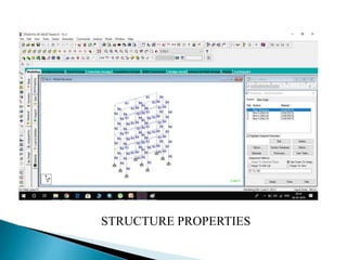
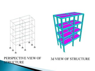
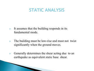
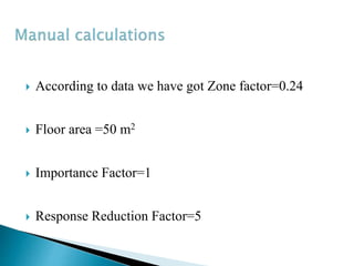
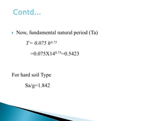
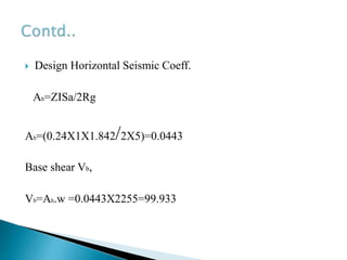
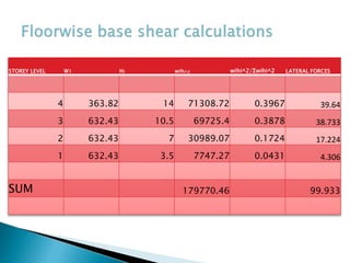
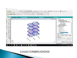
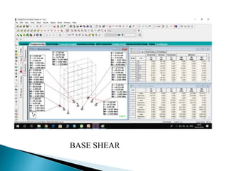
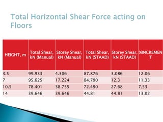
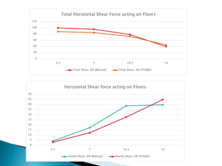
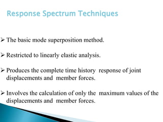
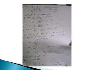
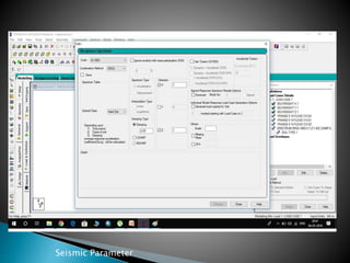
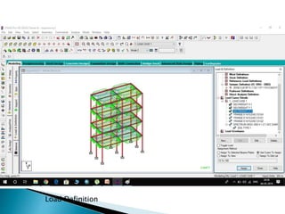
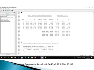
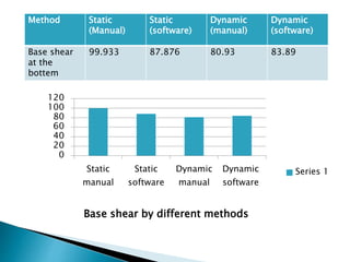
PRESENTED BY
BASIT ALI 1609100907
CHANDAN KUSHWAHA 1609100908
SHASHIKANT SINGH 1609100919
MOHD. AMAAN QUASIM 1609100914
MENTOR
Asstt. Prof. ASHUTOSH YADAV
Basic Definitions
Calculations
Static
 Manual
Manual
Staad Pro. V8i
Staad Pro. V8i
Dynamic
 Manual
Staad Pro. V8i
Result output
Conclusion
References
Contd...
The release of the energy results in vibratory
waves propagating through the surface in all
directions.
Earthquake
Earthquake is a series of vibrations induced in the earth’s
crust by the abrupt rupture and rebound of rocks in which
elastic strain has been slowly accumulating.
Response
Spectrum Analysis
Time History
Method
Earthquake Analysis
Techniques
 For the calculation we have considered four storey RCC
building which is located in seismic zone IV.
 The type of soil encountered is hard and it is proposed to design
the building with a SMRF.
 The intensity of the floors are to cater an LL of 3.5 kN/m2
 Size of Column-(250X450)mm.
 Size of Beam- Longitudinal-(250X400)mm.
Transverse-(250X350)mm.
 Depth of Slab- 100mm
 Damping-5%
 No infill Pannels
Front View
Plan
 Zone factor (Z)
 Importance Factor (I)
 Average Response Acceleration Coefficient (Sa/g)
 Response Reduction Factor (R)
• It is the indicator of the maximum seismic risk characterized
by Maximum Considered Earthquake (MCE ) in the zone in
which the structure is located.
• According to IS 1893(Part 1)-2002, Seismic Zones are
classified into II, III, IV & V respectively.
• It depends on the occupancy category of the building.
• It is obtained from table 6, Clause 6.4.2, IS 1893-2002.
 Site Class
• Site Class is determined based on the average properties of the
soil within a certain depth (30 m) from the ground surface.
• It depends on the type of rock or soil sites and also the natural
period and damping of the structure.
• It is obtained from, Clause 6.4.5, IS 1893-2002.
• It is determined by the type of lateral load resisting system
used.
• It is a measure of the system’s ability to accommodate
earthquake loads and absorb energy without collapse.
• It is obtained from table 7, IS 1893-2002.
with infil panels,
Ta=0.09h/√d
where,
h - height of the building
d- Base dimension of the building at the plinth level
• The approximate fundamental natural period of vibration ( Ta ),
of a SMRF building from Clause 7.6,
without brick infil panels,
Ta= 0.075 h0.75 for RC frame building
= 0.085 h0.75 for steel frame building
where,
Qi - Design lateral force at floor i
Wi - Seismic weight of floor i
hi - Height of floor i measured from base, and
n - Number of storey's in the building is the number of levels at
which the masses are located.
Mass of Column (0.25X10X0.4+0.25X15X0.35)X25
Mass of Beams in Long. & Trans. (0.25x0.45x3.5/2x3x25)
Mass of Slab (0.1X5X10)X25
Mass of Infill (0.25x10x0.35/2)x20+(0.15X15X3
0.5/2)X20
Imposed Load (5x10x3.5x0.5x25)
Total Weight 632.43kN =64.45 Ton
Mass of Column (0.25X10X0.4+0.25X15X0.35)X25
Mass of Beams in Long. & Trans. (0.25x.45x3.5/2x3x25)
Mass of Slab (0.1X5X10)X25
Mass of Infill (0.25x10x0.35/2)x20+(0.15X15X3.5
/2)X20
Imposed Load 0
Total Weight 363.82kN =37.087 Ton
For Roof
STRUCTURE PROPERTIES
PERSPECTIVE VIEW OF
STRUCTURE
3d VIEW OF STRUCTURE
 It assumes that the building responds in its
fundamental mode.
 The building must be low-rise and must not twist
significantly when the ground moves.
 Generally determines the shear acting due to an
earthquake as equivalent static base shear.
STATIC ANALYSIS
 According to data we have got Zone factor=0.24
 Floor area =50 m2
 Importance Factor=1
 Response Reduction Factor=5
 Now, fundamental natural period (Ta)
T= 0.075 h0.75
=0.075X140.75=0.5423
For hard soil Type
Sa/g=1.842
Contd...
 Design Horizontal Seismic Coeff.
Ah=ZISa/2Rg
Ah=(0.24X1X1.842/2X5)=0.0443
Base shear Vb,
Vb=Ah.w =0.0443X2255=99.933
STOREY LEVEL W1 Hi wihi^2 wihi^2/Σwihi^2 LATERAL FORCES
4 363.82 14 71308.72 0.3967 39.64
3 632.43 10.5 69725.4 0.3878 38.733
2 632.43 7 30989.07 0.1724 17.224
1 632.43 3.5 7747.27 0.0431 4.306
SUM 179770.46 99.933
LOAD COMBINATIONS
SEISMIC PARAMETERS
RESULT OUTPUT
BASE SHEAR
HEIGHT, m
Total Shear,
kN (Manual)
Storey Shear,
kN (Manual)
Total Shear,
kN (STAAD)
Storey Shear,
kN (STAAD)
%INCREMEN
T
3.5 99.933 4.306 87.876 3.086 12.06
7 95.625 17.224 84.790 12.3 11.33
10.5 78.401 38.755 72.490 27.68 7.53
14 39.646 39.646 44.81 44.81 13.02
0
20
40
60
80
100
120
3.5 7 10.5 14
Total Horizontal Shear Force acting on Floors
Total Shear, kN (Manual) Total Shear, kN (STAAD)
0
5
10
15
20
25
30
35
40
45
50
3.5 7 10.5 14
Horizontal Shear force acting on Floors
Storey Shear, kN (Manual) Storey Shear, kN (STAAD)
 The basic mode superposition method.
 Restricted to linearly elastic analysis.
 Produces the complete time history response of joint
displacements and member forces.
 Involves the calculation of only the maximum values of the
displacements and member forces.
Response Spectrum Techniques
Manual response spectrum calculation
Response spectrum analysis
in software
Seismic Parameter
Load Definition
Response Spectrum Result=0.0443x1893.89=83.89
Method Static
(Manual)
Static
(software)
Dynamic
(manual)
Dynamic
(software)
Base shear
at the
bottem
99.933 87.876 80.93 83.89
0
20
40
60
80
100
120
Static
manual
Static
software
Dynamic
manual
Dynamic
software
Base shear by different methods
Series 1
Dynamic analysis may be done by other methods.
Structures of nonlinear materials may be introduced for
further analysis and design.
Irregular shaped structure may be introduced for further
analysis and design.
Dynamic analysis may be introduced for further
analysis and design.
Commercial buildings may be introduced for further
Recommendation
 Static manual method gives more conservative results then
static software method for low storey building.
 As the height increases static software method gives more
horizontal shear force , so becomes more conservative then
static manual
 In this case static method came more conservative then
dynamic method but whenever we will be finding base shear
for designing any structure we will be using both the methods
and the higher value must be considered as per the IS1893
part1 provisions.
 We have got different base shear values for which we can
design shear walls as per IS13920-1993 for earthquake
resistant design of structures
 Comparison between Manual calculation and Software
calculation of G+3 Building Using Staad Pro. v8i M.A.
Qureshi 1Assistant Professor, Civil Engineering
DepartmChopra AK (1995). “Dynamics of Structures Theory
and Application to Earthquake Engineering”, University of
California at Berkeley, USA.
 Duggal S K (2010). “Earthquake Resistance Design of
Structure”, Fourth Edition, Oxford University Press, New
Delhi.
 IS 1893 Part 1 (2002). “Indian Standard Criteria for
Earthquake Resistant Design of Structures”, Bureau of Indian
Standards, New Delhi.
 Jan. T.S, Liu. M.W. and Kao. Y.C. (2004), “An upper-bond
pushover analysis procedure for estimating the seismic
demands of high-rise buildings”, Engineering structures. 117-
128.
 Nouredine Bourahla (2013), "Equivalent Static Analysis of
Structures Subjected to Seismic Actions", Encyclopedia of
Earthquake Engineering, Springer- Verlag Berlin Heidelberg.
 Pankaj Agarwal and Manish Shrikhande (2014)."Earthquake
Resistant Design of Structures", PHI Learning Private Limited,
Delhi.
Comparative Analysis of Equivalent Static Method & Dynamic Analysis Method For Seismic Load Calculation

Comparative Analysis of Equivalent Static Method & Dynamic Analysis Method For Seismic Load Calculation

  • 1.
    PRESENTED BY BASIT ALI1609100907 CHANDAN KUSHWAHA 1609100908 SHASHIKANT SINGH 1609100919 MOHD. AMAAN QUASIM 1609100914 MENTOR Asstt. Prof. ASHUTOSH YADAV
  • 2.
  • 3.
    Dynamic  Manual Staad Pro.V8i Result output Conclusion References Contd...
  • 4.
    The release ofthe energy results in vibratory waves propagating through the surface in all directions. Earthquake Earthquake is a series of vibrations induced in the earth’s crust by the abrupt rupture and rebound of rocks in which elastic strain has been slowly accumulating.
  • 5.
  • 6.
     For thecalculation we have considered four storey RCC building which is located in seismic zone IV.  The type of soil encountered is hard and it is proposed to design the building with a SMRF.  The intensity of the floors are to cater an LL of 3.5 kN/m2
  • 7.
     Size ofColumn-(250X450)mm.  Size of Beam- Longitudinal-(250X400)mm. Transverse-(250X350)mm.  Depth of Slab- 100mm  Damping-5%  No infill Pannels
  • 8.
  • 9.
     Zone factor(Z)  Importance Factor (I)  Average Response Acceleration Coefficient (Sa/g)  Response Reduction Factor (R)
  • 10.
    • It isthe indicator of the maximum seismic risk characterized by Maximum Considered Earthquake (MCE ) in the zone in which the structure is located. • According to IS 1893(Part 1)-2002, Seismic Zones are classified into II, III, IV & V respectively.
  • 11.
    • It dependson the occupancy category of the building. • It is obtained from table 6, Clause 6.4.2, IS 1893-2002.  Site Class • Site Class is determined based on the average properties of the soil within a certain depth (30 m) from the ground surface.
  • 12.
    • It dependson the type of rock or soil sites and also the natural period and damping of the structure. • It is obtained from, Clause 6.4.5, IS 1893-2002.
  • 13.
    • It isdetermined by the type of lateral load resisting system used. • It is a measure of the system’s ability to accommodate earthquake loads and absorb energy without collapse. • It is obtained from table 7, IS 1893-2002.
  • 14.
    with infil panels, Ta=0.09h/√d where, h- height of the building d- Base dimension of the building at the plinth level • The approximate fundamental natural period of vibration ( Ta ), of a SMRF building from Clause 7.6, without brick infil panels, Ta= 0.075 h0.75 for RC frame building = 0.085 h0.75 for steel frame building
  • 15.
    where, Qi - Designlateral force at floor i Wi - Seismic weight of floor i hi - Height of floor i measured from base, and n - Number of storey's in the building is the number of levels at which the masses are located.
  • 16.
    Mass of Column(0.25X10X0.4+0.25X15X0.35)X25 Mass of Beams in Long. & Trans. (0.25x0.45x3.5/2x3x25) Mass of Slab (0.1X5X10)X25 Mass of Infill (0.25x10x0.35/2)x20+(0.15X15X3 0.5/2)X20 Imposed Load (5x10x3.5x0.5x25) Total Weight 632.43kN =64.45 Ton
  • 17.
    Mass of Column(0.25X10X0.4+0.25X15X0.35)X25 Mass of Beams in Long. & Trans. (0.25x.45x3.5/2x3x25) Mass of Slab (0.1X5X10)X25 Mass of Infill (0.25x10x0.35/2)x20+(0.15X15X3.5 /2)X20 Imposed Load 0 Total Weight 363.82kN =37.087 Ton For Roof
  • 18.
  • 19.
  • 21.
     It assumesthat the building responds in its fundamental mode.  The building must be low-rise and must not twist significantly when the ground moves.  Generally determines the shear acting due to an earthquake as equivalent static base shear. STATIC ANALYSIS
  • 22.
     According todata we have got Zone factor=0.24  Floor area =50 m2  Importance Factor=1  Response Reduction Factor=5
  • 23.
     Now, fundamentalnatural period (Ta) T= 0.075 h0.75 =0.075X140.75=0.5423 For hard soil Type Sa/g=1.842 Contd...
  • 24.
     Design HorizontalSeismic Coeff. Ah=ZISa/2Rg Ah=(0.24X1X1.842/2X5)=0.0443 Base shear Vb, Vb=Ah.w =0.0443X2255=99.933
  • 25.
    STOREY LEVEL W1Hi wihi^2 wihi^2/Σwihi^2 LATERAL FORCES 4 363.82 14 71308.72 0.3967 39.64 3 632.43 10.5 69725.4 0.3878 38.733 2 632.43 7 30989.07 0.1724 17.224 1 632.43 3.5 7747.27 0.0431 4.306 SUM 179770.46 99.933
  • 26.
  • 27.
  • 28.
  • 29.
  • 30.
    HEIGHT, m Total Shear, kN(Manual) Storey Shear, kN (Manual) Total Shear, kN (STAAD) Storey Shear, kN (STAAD) %INCREMEN T 3.5 99.933 4.306 87.876 3.086 12.06 7 95.625 17.224 84.790 12.3 11.33 10.5 78.401 38.755 72.490 27.68 7.53 14 39.646 39.646 44.81 44.81 13.02
  • 31.
    0 20 40 60 80 100 120 3.5 7 10.514 Total Horizontal Shear Force acting on Floors Total Shear, kN (Manual) Total Shear, kN (STAAD) 0 5 10 15 20 25 30 35 40 45 50 3.5 7 10.5 14 Horizontal Shear force acting on Floors Storey Shear, kN (Manual) Storey Shear, kN (STAAD)
  • 33.
     The basicmode superposition method.  Restricted to linearly elastic analysis.  Produces the complete time history response of joint displacements and member forces.  Involves the calculation of only the maximum values of the displacements and member forces. Response Spectrum Techniques
  • 34.
  • 40.
  • 41.
  • 42.
  • 43.
  • 44.
    Method Static (Manual) Static (software) Dynamic (manual) Dynamic (software) Base shear atthe bottem 99.933 87.876 80.93 83.89 0 20 40 60 80 100 120 Static manual Static software Dynamic manual Dynamic software Base shear by different methods Series 1
  • 45.
    Dynamic analysis maybe done by other methods. Structures of nonlinear materials may be introduced for further analysis and design. Irregular shaped structure may be introduced for further analysis and design. Dynamic analysis may be introduced for further analysis and design. Commercial buildings may be introduced for further Recommendation
  • 46.
     Static manualmethod gives more conservative results then static software method for low storey building.  As the height increases static software method gives more horizontal shear force , so becomes more conservative then static manual  In this case static method came more conservative then dynamic method but whenever we will be finding base shear for designing any structure we will be using both the methods and the higher value must be considered as per the IS1893 part1 provisions.  We have got different base shear values for which we can design shear walls as per IS13920-1993 for earthquake resistant design of structures
  • 47.
     Comparison betweenManual calculation and Software calculation of G+3 Building Using Staad Pro. v8i M.A. Qureshi 1Assistant Professor, Civil Engineering DepartmChopra AK (1995). “Dynamics of Structures Theory and Application to Earthquake Engineering”, University of California at Berkeley, USA.  Duggal S K (2010). “Earthquake Resistance Design of Structure”, Fourth Edition, Oxford University Press, New Delhi.  IS 1893 Part 1 (2002). “Indian Standard Criteria for Earthquake Resistant Design of Structures”, Bureau of Indian Standards, New Delhi.
  • 48.
     Jan. T.S,Liu. M.W. and Kao. Y.C. (2004), “An upper-bond pushover analysis procedure for estimating the seismic demands of high-rise buildings”, Engineering structures. 117- 128.  Nouredine Bourahla (2013), "Equivalent Static Analysis of Structures Subjected to Seismic Actions", Encyclopedia of Earthquake Engineering, Springer- Verlag Berlin Heidelberg.  Pankaj Agarwal and Manish Shrikhande (2014)."Earthquake Resistant Design of Structures", PHI Learning Private Limited, Delhi.