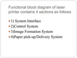
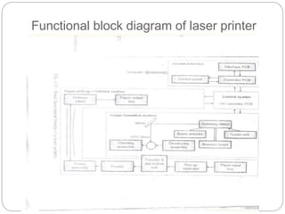
Presented by :
Kartik N. Kalpande
Functional block diagram of laser
printer
Functional block diagram of laser
printer contains 4 sections as follows
 1) System Interface
 2)Control System
 3)Image Formation System
 4)Paper pick-up/Delivery System
Functional block diagram of laser printer
System Interface
The use of system interface:
 Communication with host computer through I/O
ports
 Monitor the user’s selection on printer control
panel and display printer status information to the
user.
 Store configuration information.
 manipulate the data or information into proper
format.
Control System
 Coordinating all the activities of the printer
required for the printing process.
 To drive the laser beam.
 Properly coordinate the image data from the
interface assembly.
 It also controls and monitors the paper motion ,
the high voltage system, erase lamp and all
motors.
 It also shares machine status information with the
interface.
Image Formation System
 To form an image on the paper a laser requires
electronics, mechanical, optical, electro
photographical etc. many different technologies.
 inside a laser printer the image formation
process revolved around an OPC drum (organic
photo conductive).
 The complete image formation process consists
of the six steps
1. Clearing of the OPC drum.
Image Formation System
(contd..)
2. Conditioning of the OPC drum (the uniform
charge of -600 v is applied to the complete
surface of OPC drum).
3. Electro statically writing the image onto the
OPC drum (to write data a laser beam is
focused on the selected areas of the drum).
4. Developing the image on the OPC drum (To
develop a latent image into a visible image).
5. Transferring of the image from OPC drum to the
paper.
6. Fusing the image on the paper (This makes the
permanent image).
Paper Pick-up/Delivery System
 This System is responsible for :
 Picking the paper from the input tray.
 Delivering the paper to the image formation
system at the right time.
 Feeding it to the fusing station and
 Delivering it to the output tray.
Thank You..!!
Any Questions or
Queries

Functional block diagram_of_laser_printer

  • 1.
    Presented by : KartikN. Kalpande Functional block diagram of laser printer
  • 2.
    Functional block diagramof laser printer contains 4 sections as follows  1) System Interface  2)Control System  3)Image Formation System  4)Paper pick-up/Delivery System
  • 3.
    Functional block diagramof laser printer
  • 4.
    System Interface The useof system interface:  Communication with host computer through I/O ports  Monitor the user’s selection on printer control panel and display printer status information to the user.  Store configuration information.  manipulate the data or information into proper format.
  • 5.
    Control System  Coordinatingall the activities of the printer required for the printing process.  To drive the laser beam.  Properly coordinate the image data from the interface assembly.  It also controls and monitors the paper motion , the high voltage system, erase lamp and all motors.  It also shares machine status information with the interface.
  • 6.
    Image Formation System To form an image on the paper a laser requires electronics, mechanical, optical, electro photographical etc. many different technologies.  inside a laser printer the image formation process revolved around an OPC drum (organic photo conductive).  The complete image formation process consists of the six steps 1. Clearing of the OPC drum.
  • 7.
    Image Formation System (contd..) 2.Conditioning of the OPC drum (the uniform charge of -600 v is applied to the complete surface of OPC drum). 3. Electro statically writing the image onto the OPC drum (to write data a laser beam is focused on the selected areas of the drum). 4. Developing the image on the OPC drum (To develop a latent image into a visible image). 5. Transferring of the image from OPC drum to the paper. 6. Fusing the image on the paper (This makes the permanent image).
  • 8.
    Paper Pick-up/Delivery System This System is responsible for :  Picking the paper from the input tray.  Delivering the paper to the image formation system at the right time.  Feeding it to the fusing station and  Delivering it to the output tray.
  • 9.