
Recommended
More Related Content
What's hot
What's hot (20)
Similar to PCI
Similar to PCI (20)
More from ITz_1
Recently uploaded
Recently uploaded (20)
PCI
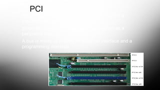
- 1. PCI The peripheral component interconnect (PCI) is a popular high-bandwidth, processor-independent bus that can function as a peripheral bus. A bus is made up of both an electrical interface and a programming interface
- 2. The PCI Interface • A replacement for the ISA standard (bare metal kind of bus) • Goals • Better performance • Platform independence • Simplify adding and removing peripherals to the system
- 3. • Compared with other common bus specifications, PCI delivers better system performance • for high-speed I/O subsystems (e.g., graphic display adapters, network interface controllers, disk controllers, and so on)expansion PCI Slots CPU RAM
- 4. • The older buses were having speed of almost few mega bytes per second • The PCI data lines having frequency of 66 MHz • For a raw transfer rate of 528 MByte/s, or4.224 Gbps. • It is designed to meet economically the I/O requirements of modern systems. • It requires very few chips to implement and supports other buses attached to the PCI bus. • PCI is designed to support a variety of microprocessor-based configurations , including both single- and multiple-processor systems. • It makes use of synchronous timing
- 8. (a) Typical desktop system
- 10. Bus Structure PCI may be configured as a 32- or 64-bit ->These are divided into the following functional groups: • System pins: Include the clock and reset pins. • Address and data pins: Include 32 lines that are time multiplexed for addresses and data. • Interface control pins: Control the timing of transactions and provide coordination among initiators and targets. • Arbitration pins: PCI master has its own pair of arbitration lines that connect it directly to the PCI bus arbiter.
- 11. • • Error reporting pins: • Used to report parity and other errors. • • Interrupt pins: These are provided for PCI devices that must generate requests for service. As with the arbitration pins, these a not shared lines. Rather, each PCI device has its own interrupt line controller. Cache support pins: These pins are needed to support a memory on PCI that can be cached in the processor or another device. These pins support snoop. 64-bit bus extension pins: Include 32 lines that are time multiplexed for addresses and data and that are combined with the mandatory address/data lines to form a 64-bit address/data bus. • • JTAG/boundary scan pins: These signal lines support testing procedures defined in IEEE Standard 1149.1.
- 12. PCI Commands Bus activity occurs in the form of transactions between an initiator, and a target. When a bus initiator acquires control of the bus, it determines the type of transaction that will occur next. commands are as follows: • Interrupt Acknowledge • Special Cycle • I/O Read • I/O Write • Memory Read • Memory Write • Memory Write and Invalidate • Configuration Read • Configuration Write • Dual address Cycle
Editor's Notes
- <number>