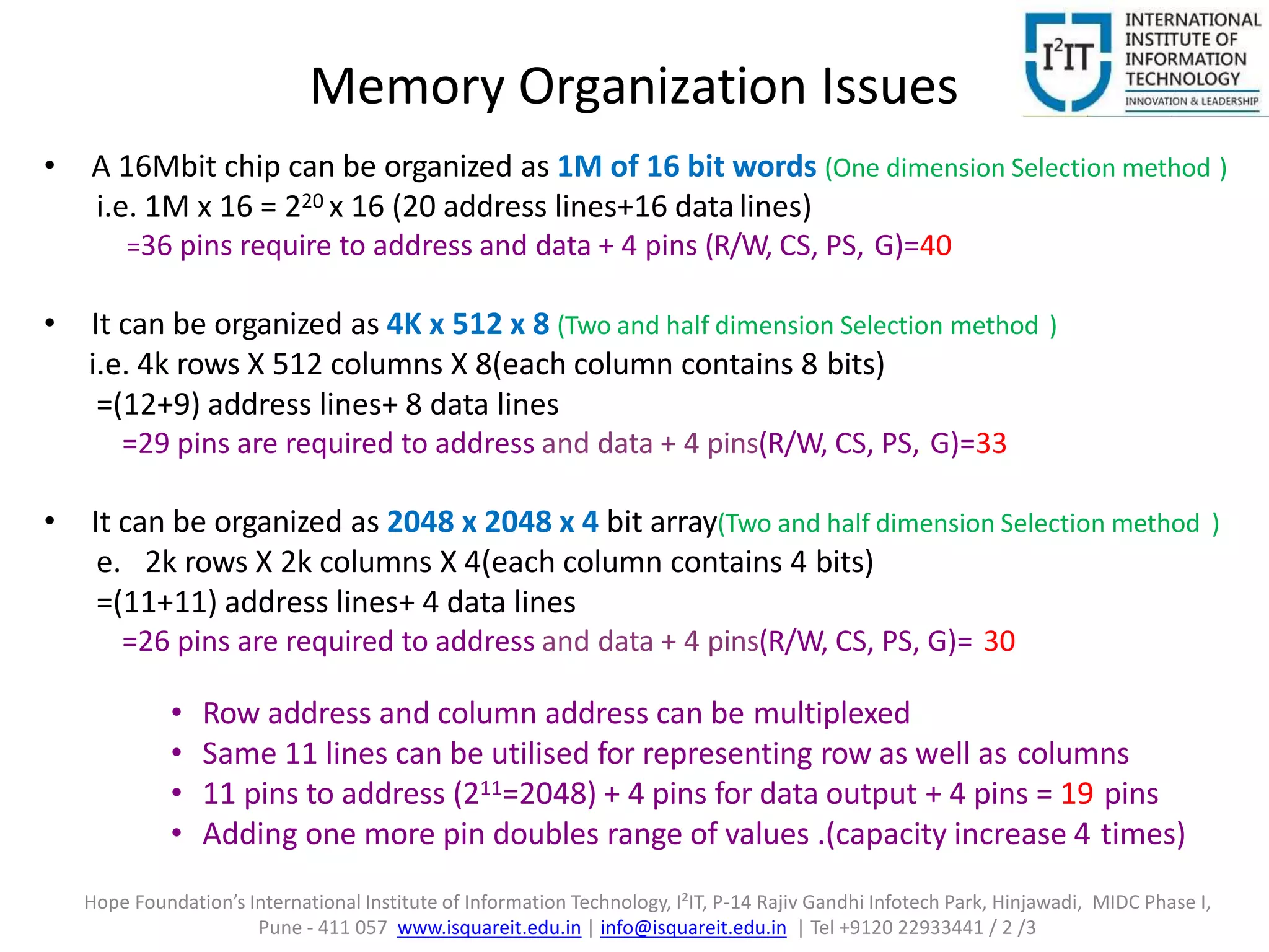
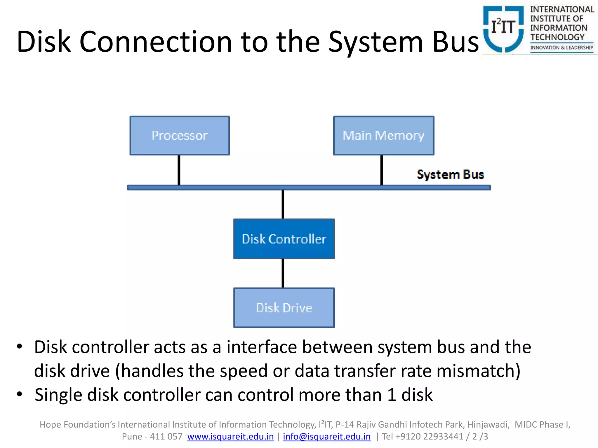
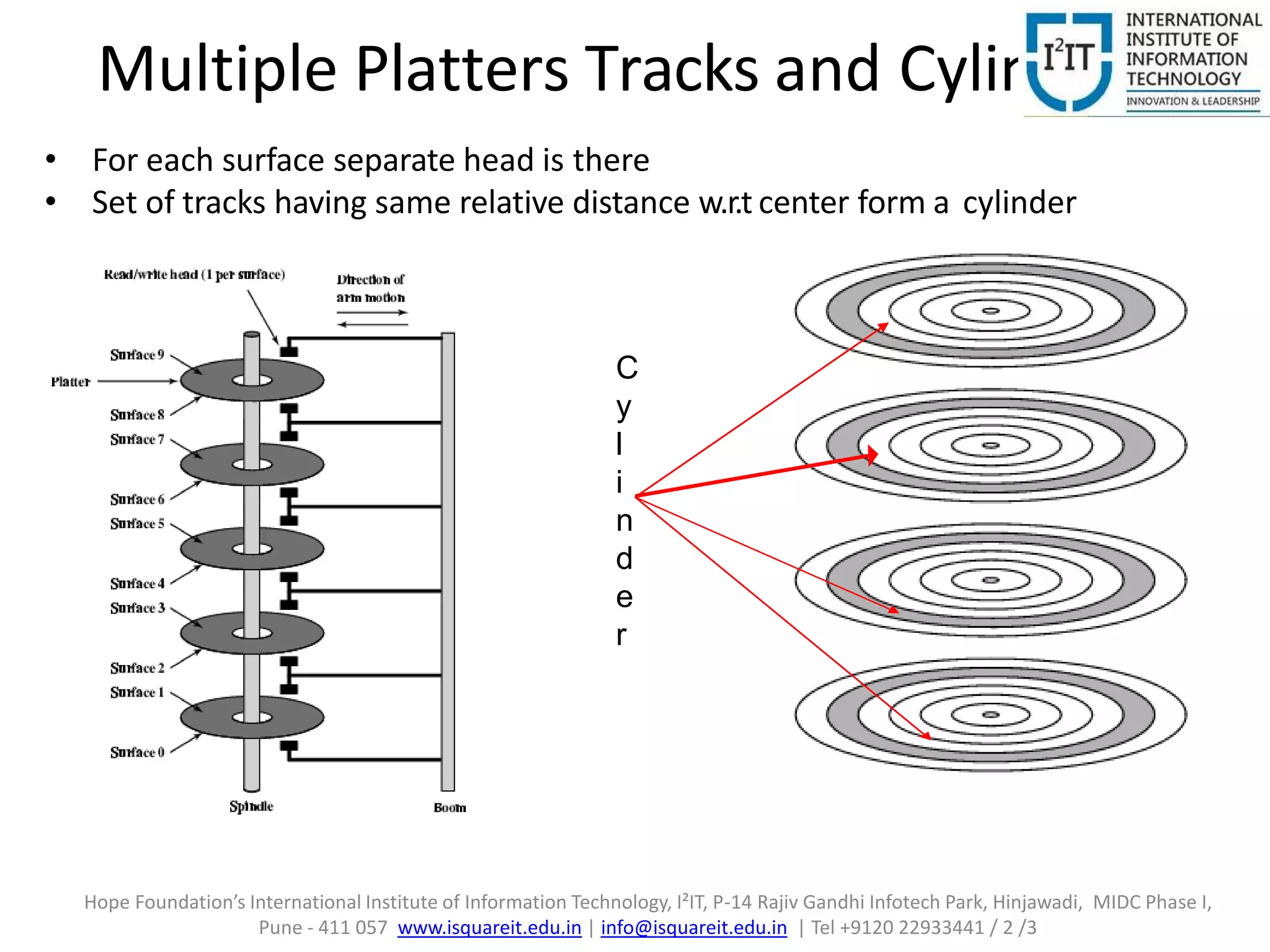
Memory organization is a classification of memory or a class presentation of memory in which the memory is categorized or sub divided according to their work.
HARDNESS, FRACTURE TOUGHNESS AND STRENGTH OF CERAMICS
COA | Memory Organization
1. Memory Organization
Prof. Bailappa. Bhovi
Department of Computer Engineering
Hope Foundation’s
International Institute of Information Technology, (I²IT).
www.isquareit.edu.in
Tel - +91 20 22933441
2. UNIT-2:
Internal memory organization
Hope Foundation’s International Institute of Information Technology, I²IT, P-14 Rajiv Gandhi Infotech Park, Hinjawadi, MIDC Phase I,
Pune - 411 057 www.isquareit.edu.in | info@isquareit.edu.in | Tel +9120 22933441 / 2 /3
3. Memory- Basic Concepts
• Data transfer between the processor and the memory takes
place through the two registers
– MAR and MBR or MDR
• MAR: The address from which data has to be read/write from
memory
• MBR: The data contents send by memory after supplying
address by MAR
• Memory Speed measurement
– Memory Access Time
– Memory Cycle Time
• Memory cycle time(Access time + Recovery time )
– Memory Cycle time for Semiconductor memories ranges 10
to 100 ns
Hope Foundation’s International Institute of Information Technology, I²IT, P-14 Rajiv Gandhi Infotech Park, Hinjawadi, MIDC Phase I,
Pune - 411 057 www.isquareit.edu.in | info@isquareit.edu.in | Tel +9120 22933441 / 2 /3
4. Semiconductor Memory Types
Memory Type Category Erasure
Write
Mechanism
Volatility
Random-access
memory (RAM)
Read-write
memory
Electrically,
byte-level
Electrically Volatile
Read-only
memory (ROM) Read-only
memory
Not possible
Masks
Nonvolatile
Programmable
ROM (PROM)
Electrically
Erasable PROM
(EPROM)
Read-mostly
memory
UV light, chip-
level
Electrically
Erasable PROM
(EEPROM)
Electrically,
byte-level
Flash memory
Electrically,
block-level
Hope Foundation’s International Institute of Information Technology, I²IT, P-14 Rajiv Gandhi Infotech Park, Hinjawadi, MIDC Phase I,
Pune - 411 057 www.isquareit.edu.in | info@isquareit.edu.in | Tel +9120 22933441 / 2 /3
5. Static RAM
• Memories that consists of circuits capable of
retaining their state as long as power is applied
• Bits stored as on/off switches
• Complex construction (density less)
so larger per bit and more expensive
• Faster operations, used for cache memory
Dynamic RAM
• Bits stored as charge in capacitors charges leak
so need refreshing even when powered
• Simpler construction
• Smaller per bit so less expensive
• Address line active when bit read or written
• Slower operations, used for main memory
Hope Foundation’s International Institute of Information Technology, I²IT, P-14 Rajiv Gandhi Infotech Park, Hinjawadi, MIDC Phase I,
Pune - 411 057 www.isquareit.edu.in | info@isquareit.edu.in | Tel +9120 22933441 / 2 /3
6. Memory Chip Organization
One dimensional Selection method
Each row of memory cell(array of memory cells) forms one word of memory
Toaddress this mem,a decoder is reqd.Each location can be identified using A0-A3 bits.
For any location, its corresponding data can be identified at b0-b7 data lines
Pins reqd for memory: 4(address lines) + 8 (data lines)+1(CS)+1(R/W)+2(Vcc ,Gnd)=16
16 rows X 8 columns = 128 bits.
8 bit/chip organization
Hope Foundation’s International Institute of Information Technology, I²IT, P-14 Rajiv Gandhi Infotech Park, Hinjawadi, MIDC Phase I,
Pune - 411 057 www.isquareit.edu.in | info@isquareit.edu.in | Tel +9120 22933441 / 2 /3
7. Two dimensional Selection method
• Memory organised as matrix of cells, each of which stores a bit
• A particular cell is selected using row and column decoder
• Row decoder selects a particular row
• Column decoder selects a particular Column
• Cheaper to implement
Hope Foundation’s International Institute of Information Technology, I²IT, P-14 Rajiv Gandhi Infotech Park, Hinjawadi, MIDC Phase I,
Pune - 411 057 www.isquareit.edu.in | info@isquareit.edu.in | Tel +9120 22933441 / 2 /3
8. Organization of a 1K 1 Memory Chip
(Two dimensional Selection method )
Pins reqd for memory: 10(address lines) + 1 (data line)+1(CS)+1(R/W)+2(Vcc,Gnd)=15
This design is called 1 bit/chip organization (more preferred )
Hope Foundation’s International Institute of Information Technology, I²IT, P-14 Rajiv Gandhi Infotech Park, Hinjawadi, MIDC Phase I,
Pune - 411 057 www.isquareit.edu.in | info@isquareit.edu.in | Tel +9120 22933441 / 2 /3
9. Memory Organization Issues
• A 16Mbit chip can be organized as 1M of 16 bit words (One dimension Selection method )
i.e. 1M x 16 = 220 x 16 (20 address lines+16 datalines)
=36 pins require to address and data + 4 pins (R/W, CS, PS, G)=40
• It can be organized as 4K x 512 x 8 (Two and half dimension Selection method )
i.e. 4k rows X 512 columns X 8(each column contains 8 bits)
=(12+9) address lines+ 8 data lines
=29 pins are required to address and data + 4 pins(R/W, CS, PS, G)=33
• It can be organized as 2048 x 2048 x 4 bit array(Two and half dimension Selection method )
e. 2k rows X 2k columns X 4(each column contains 4 bits)
=(11+11) address lines+ 4 data lines
=26 pins are required to address and data + 4 pins(R/W, CS, PS, G)= 30
• Row address and column address can be multiplexed
• Same 11 lines can be utilised for representing row as well as columns
• 11 pins to address (211=2048) + 4 pins for data output + 4 pins = 19 pins
• Adding one more pin doubles range of values .(capacity increase 4 times)
Hope Foundation’s International Institute of Information Technology, I²IT, P-14 Rajiv Gandhi Infotech Park, Hinjawadi, MIDC Phase I,
Pune - 411 057 www.isquareit.edu.in | info@isquareit.edu.in | Tel +9120 22933441 / 2 /3
10. 16 Mbit DRAM Organization
Row decoder- Toselect a row from 2k rows
RAS-Row address selector ,CAS – Column address selector
• On 11 bit address lines,1st row address will appear so that row is identified
• Next on same 11 bit address lines, column address will appear so that column is identified
• Thus location once identified, can transfer its 4 bits to D1-D4 th’ Data o/p buffer for Read opn
• And for a write opn D1-D4 has data which is transferred th’ i/p buffer to identified location
• Adv: Pins reduced to half ,Disadv : More time
2048 x 2048 x 4 = 16Mb (Two and half dimension
Selection method )
Hope Foundation’s International Institute of Information Technology, I²IT, P-14 Rajiv Gandhi Infotech Park, Hinjawadi, MIDC Phase I,
Pune - 411 057 www.isquareit.edu.in | info@isquareit.edu.in | Tel +9120 22933441 / 2 /3
11. Synchronous DRAM (SDRAM)
• Synchronized with processor clock
• After Read command, data appears after a latency of 2 clock pulses
• This 2 clk cycle wait can be utilized by the processor for activities
that does not need the system bus, e.g. ALU operations
Hope Foundation’s International Institute of Information Technology, I²IT, P-14 Rajiv Gandhi Infotech Park, Hinjawadi, MIDC Phase I,
Pune - 411 057 www.isquareit.edu.in | info@isquareit.edu.in | Tel +9120 22933441 / 2 /3
12. DDR SDRAM Read Timing
• Dual Data rate(DDR) :Each cycle provides 2 bytes of data
• Data transfer rate double as compared to SDRAM
Hope Foundation’s International Institute of Information Technology, I²IT, P-14 Rajiv Gandhi Infotech Park, Hinjawadi, MIDC Phase I,
Pune - 411 057 www.isquareit.edu.in | info@isquareit.edu.in | Tel +9120 22933441 / 2 /3
13. External memory
• Semiconductor memory can not be used to
store large amount of information or data
– Due to high per bit cost of it!
• Large storage requirements is full filled by
– Magnetic disks, Optical disks and Magnetic tapes
– Called as secondary storage
Hope Foundation’s International Institute of Information Technology, I²IT, P-14 Rajiv Gandhi Infotech Park, Hinjawadi, MIDC Phase I,
Pune - 411 057 www.isquareit.edu.in | info@isquareit.edu.in | Tel +9120 22933441 / 2 /3
14. Disk Connection to the System Bus
• Disk controller acts as a interface between system bus and the
disk drive (handles the speed or data transfer rate mismatch)
• Single disk controller can control more than 1 disk
Hope Foundation’s International Institute of Information Technology, I²IT, P-14 Rajiv Gandhi Infotech Park, Hinjawadi, MIDC Phase I,
Pune - 411 057 www.isquareit.edu.in | info@isquareit.edu.in | Tel +9120 22933441 / 2 /3
15. Data Organization on Disk
• Hard disk divided into tracks and sectors
• Concentric rings called tracks
– Gaps between tracks
– Same number of bits per track
– Constant angular velocity
• Tracks divided into sectors
• Minimum block size is one sector-512
bytes can be read/written at a time
• Individual tracks and sectors addressable
• For reading particular info, the head has
to move desired track and then the disk
has to rotate so that desired sector
comes under the head
• Direct + sequential access method
Hope Foundation’s International Institute of Information Technology, I²IT, P-14 Rajiv Gandhi Infotech Park, Hinjawadi, MIDC Phase I,
Pune - 411 057 www.isquareit.edu.in | info@isquareit.edu.in | Tel +9120 22933441 / 2 /3
16. Multi Zone Recording Disks
Single – zone recording disc Multi Zone Recording Disks
• Linear distance of innermost track is less than
that of outermost track
• Density of bits more in inner sectors/tracks.
• For outer tracks we are wasting recording space
in CAV(Constant angular velocity ) system
• Solution : Multi Zone Recording Disks
• Better space utilization
• Linear length of sector is same
• More sectors as we go outwards
• For each zone the recording/reading
speed will be different
i.e. Zone wise velocity will be different
Hope Foundation’s International Institute of Information Technology, I²IT, P-14 Rajiv Gandhi Infotech Park, Hinjawadi, MIDC Phase I,
Pune - 411 057 www.isquareit.edu.in | info@isquareit.edu.in | Tel +9120 22933441 / 2 /3
17. Multiple Platters Tracks and Cylinders
C
y
l
i
n
d
e
r
• For each surface separate head is there
• Set of tracks having same relative distance w.r.t center form a cylinder
Hope Foundation’s International Institute of Information Technology, I²IT, P-14 Rajiv Gandhi Infotech Park, Hinjawadi, MIDC Phase I,
Pune - 411 057 www.isquareit.edu.in | info@isquareit.edu.in | Tel +9120 22933441 / 2 /3
18. Capacity
• Capacity generally express in units of gigabytes (GB),
where 1 GB =10^9 Byte
• Capacity is determined by these technology factors:
– Recording density (bits/inch): number of bits that can be
squeezed into a 1 inch segment of a track.
– Track density (tracks/inch): number of tracks that can be
squeezed into a 1 inch radial segment.
– Areal density (bits/sq.inch): product of recording and track
density.
• Modern disks partition tracks into disjoint
subsets called recording zones(multiple zone
disc)
Hope Foundation’s International Institute of Information Technology, I²IT, P-14 Rajiv Gandhi Infotech Park, Hinjawadi, MIDC Phase I,
Pune - 411 057 www.isquareit.edu.in | info@isquareit.edu.in | Tel +9120 22933441 / 2 /3
19. Computing Disk Capacity
• Capacity =(# bytes/sector) x (avg. # sectors/track) x
(# tracks/surface) x (# surfaces/platter) x (#
platters/disk)
• Example:
– 512 bytes/sector, 300 sectors/track (average)
– 20,000 tracks/surface, 2 surfaces/platter
– 5 platters/disk
– Capacity = 512 x 300 x 20000 x 2 x 5 = 30.72GB
Hope Foundation’s International Institute of Information Technology, I²IT, P-14 Rajiv Gandhi Infotech Park, Hinjawadi, MIDC Phase I,
Pune - 411 057 www.isquareit.edu.in | info@isquareit.edu.in | Tel +9120 22933441 / 2 /3
20. Computing Disk Capacity
• Capacity =(# bytes/sector) x (avg. # sectors/track) x
(# tracks/surface) x (# surfaces/platter) x (#
platters/disk)
• Example:
– 512 bytes/sector, 200 sectors/track (average)
– 50,000 tracks/surface, 2 surfaces/platter
– 3 platters/disk.
– Find the capacity.
Hope Foundation’s International Institute of Information Technology, I²IT, P-14 Rajiv Gandhi Infotech Park, Hinjawadi, MIDC Phase I,
Pune - 411 057 www.isquareit.edu.in | info@isquareit.edu.in | Tel +9120 22933441 / 2 /3
21. Disk Performance Parameters
• Access time for disc is greater than that for cache/main memory or
semiconductor memory.
• Seek time (Ts)
– Time require to positioned the head on the desired track
(in ms due to mechanical system)
• Rotational delay
– Time require to positioned desired sector under r/w head
(for each sector rotation is different, thus consider average rotation)
• Transfer time
-- Time required for reading /recording disk
• The Total average access time is: Ta= Ts+
1/2r + b/rN
– Here Tsis Average seek time
– r is rotation speed in revolution per second
– b number of bytes to be transferred
– N number of bytes on a track
Hope Foundation’s International Institute of Information Technology, I²IT, P-14 Rajiv Gandhi Infotech Park, Hinjawadi, MIDC Phase I,
Pune - 411 057 www.isquareit.edu.in | info@isquareit.edu.in | Tel +9120 22933441 / 2 /3
22. Performance Improvement in
Secondary Storage
• In general multiple components improves the performance
• Similarly multiple disks should reduce access time?
– Arrays of disks operates independently and in parallel
– Also used as standby if one or more disk fails
– Used where response time is critical
• Justification
– With multiple disks separate I/O requests can be handled
in parallel
– A single I/O request can be executed in parallel, if the
requested data is distributed across multiple disks
• Researchers @ University of California-Berkeley proposed the
RAID (1988)
Hope Foundation’s International Institute of Information Technology, I²IT, P-14 Rajiv Gandhi Infotech Park, Hinjawadi, MIDC Phase I,
Pune - 411 057 www.isquareit.edu.in | info@isquareit.edu.in | Tel +9120 22933441 / 2 /3
23. RAID
• Redundant Array of Independent Disks
• Seven levels in common use
• Not a hierarchy
• Characteristics
1. Set of physical disks viewed as single logical drive
by operating system
2. Data distributed across physical drives
3. Can use redundant capacity to store parity
information
Hope Foundation’s International Institute of Information Technology, I²IT, P-14 Rajiv Gandhi Infotech Park, Hinjawadi, MIDC Phase I,
Pune - 411 057 www.isquareit.edu.in | info@isquareit.edu.in | Tel +9120 22933441 / 2 /3
24. Data Mapping in RAID 0
No redundancy
Data striped across all
disks Round Robin striping
• Data is distributed across the disk in strips :0,1,2,3
• Work distributed among 4 disks
Increased Speed
• Multiple data requests probably not on same disk
• Disks seek in parallel
• A set of data is likely to be striped across multiple disks
Draw Backs:
• Not a "True" RAID because it is NOT fault-tolerant
• The failure of just one drive will result in all data in an array being lost
Hope Foundation’s International Institute of Information Technology, I²IT, P-14 Rajiv Gandhi Infotech Park, Hinjawadi, MIDC Phase I,
Pune - 411 057 www.isquareit.edu.in | info@isquareit.edu.in | Tel +9120 22933441 / 2 /3
25. RAID 1
Mirrored Disks ,Data is striped across disks
2 copies of each stripe on separate disks
In case hard disk fails, parallel disk can work
Read from either and Write to both
If N is no.of data disk ,then Redundency-2N
Recovery is simple
• Swap faulty disk & re-mirror
• No down time
Draw back
• Highest disk overhead of all RAID types (For any write,2 copies are to be made
• Expensive
• Any write should be done on two disks
Hope Foundation’s International Institute of Information Technology, I²IT, P-14 Rajiv Gandhi Infotech Park, Hinjawadi, MIDC Phase I,
Pune - 411 057 www.isquareit.edu.in | info@isquareit.edu.in | Tel +9120 22933441 / 2 /3
26. Data Mapping in RAID 2
Lots of redundancy
Expensive: Good for erroneous disk
If N is no.of data disk ,then Redundancy- logN
Use parallel access technique
• Very small size strips
• Error correcting code is calculated across corresponding bits on each data disks
• Multiple parity disks store Hamming code error correction in corresponding
positions
Some parity info of data is stored so that if any disk fails, then data can be recovered.
Hope Foundation’s International Institute of Information Technology, I²IT, P-14 Rajiv Gandhi Infotech Park, Hinjawadi, MIDC Phase I,
Pune - 411 057 www.isquareit.edu.in | info@isquareit.edu.in | Tel +9120 22933441 / 2 /3
27. Data Mapping in RAID 3
Similar to RAID 2
• Bit interleaved parity used
• Only one redundant disk, no matter how large the array
• Simple parity bit for each set of corresponding bits
• Data on failed drive can be reconstructed from surviving data and parity information
e.g. For ith bit, parity will be stored as: X4(i) = X3 (i) xor X2(i) xor X1 (i) xor X0 (i)
• If X2 disc is failed ,its data can be recovered as follows: Xoring X4 (i) xor
X2(i) on both sides of equation ,we get: X2(i) = X3 (i) xor X1 (i) xor X0
(i) xor X4(i)
X0 X1 X2 X3 X4
Hope Foundation’s International Institute of Information Technology, I²IT, P-14 Rajiv Gandhi Infotech Park, Hinjawadi, MIDC Phase I,
Pune - 411 057 www.isquareit.edu.in | info@isquareit.edu.in | Tel +9120 22933441 / 2 /3
28. RAID 4
• Make use of independent access with block level striping
• Good for high I/O request rate due to large strips
• Bit by bit parity calculated across stripes on each disk
• Parity stored on parity disk
• If N is no.of data disk ,then N+1 are total disk reqd.
• If any disk gets modified, then Parity disk will get modified
simultaneously ,thus a long queue can be there for writing parity
info. corresponding to the blocks
Hope Foundation’s International Institute of Information Technology, I²IT, P-14 Rajiv Gandhi Infotech Park, Hinjawadi, MIDC Phase I,
Pune - 411 057 www.isquareit.edu.in | info@isquareit.edu.in | Tel +9120 22933441 / 2 /3
29. RAID 5
• Parity disc distributed along each disk(No.of disk are same)
• Round robin allocation for parity stripe
• It avoids RAID 4 bottleneck at parity disk
• Commonly used in network servers
• Drawback
– Disk failure has a medium impact on throughput
– Difficult to rebuild in the event of a disk failure (as
compared to RAID level 1)
Hope Foundation’s International Institute of Information Technology, I²IT, P-14 Rajiv Gandhi Infotech Park, Hinjawadi, MIDC Phase I,
Pune - 411 057 www.isquareit.edu.in | info@isquareit.edu.in | Tel +9120 22933441 / 2 /3
30. RAID 6
• Two parity calculations are distributed along the disk
• Stored in separate blocks on different disks
• If 2 disk fail, then also data can be recovered
• If N is no.of data disk ,then N+2 are total disk reqd.
• High data availability
– Three disks need to fail for data loss
– Significant write penalty
• Drawback
– Controller overhead to compute parity is very high
Hope Foundation’s International Institute of Information Technology, I²IT, P-14 Rajiv Gandhi Infotech Park, Hinjawadi, MIDC Phase I,
Pune - 411 057 www.isquareit.edu.in | info@isquareit.edu.in | Tel +9120 22933441 / 2 /3
31. THANK YOU
For further information please contact
Bailappa Bhovi
Department of Computer Engineering
Hope Foundation’s
International Institute of Information Technology, I²IT
P-14, Rajiv Gandhi Infotech Park, MIDC Phase 1, Hinjawadi,
Pune – 411 057
Phone - +91 20 22933441
www.isquareit.edu.in | bailappab@isquareit.edu.in|
info@isquareit.edu.in