AIRCRAFT WHEELS
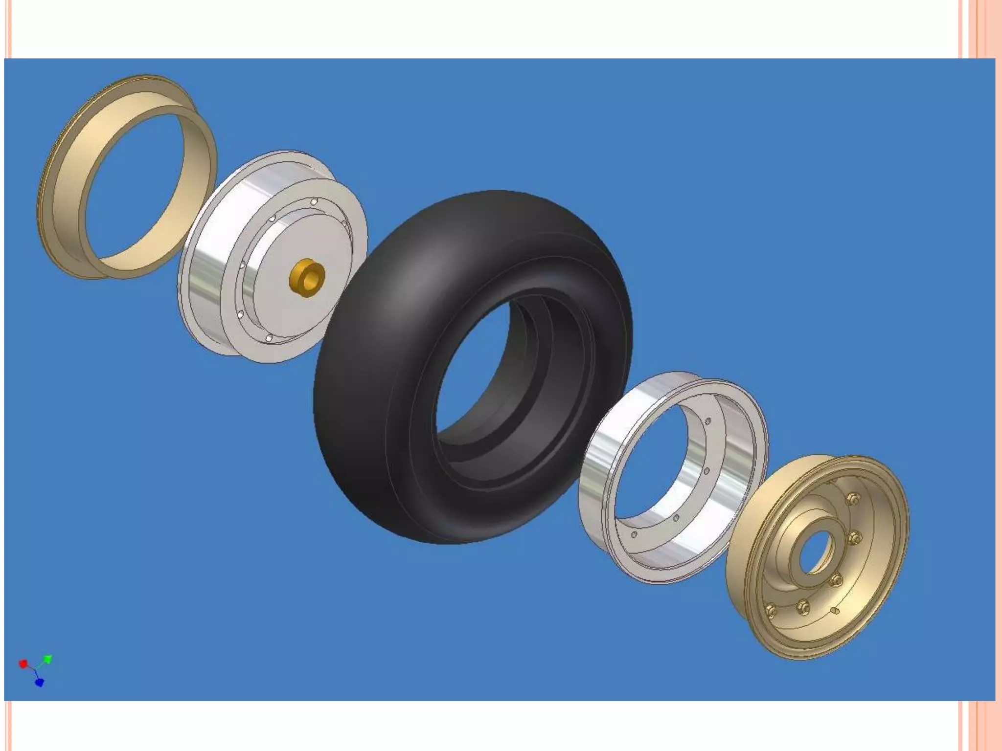
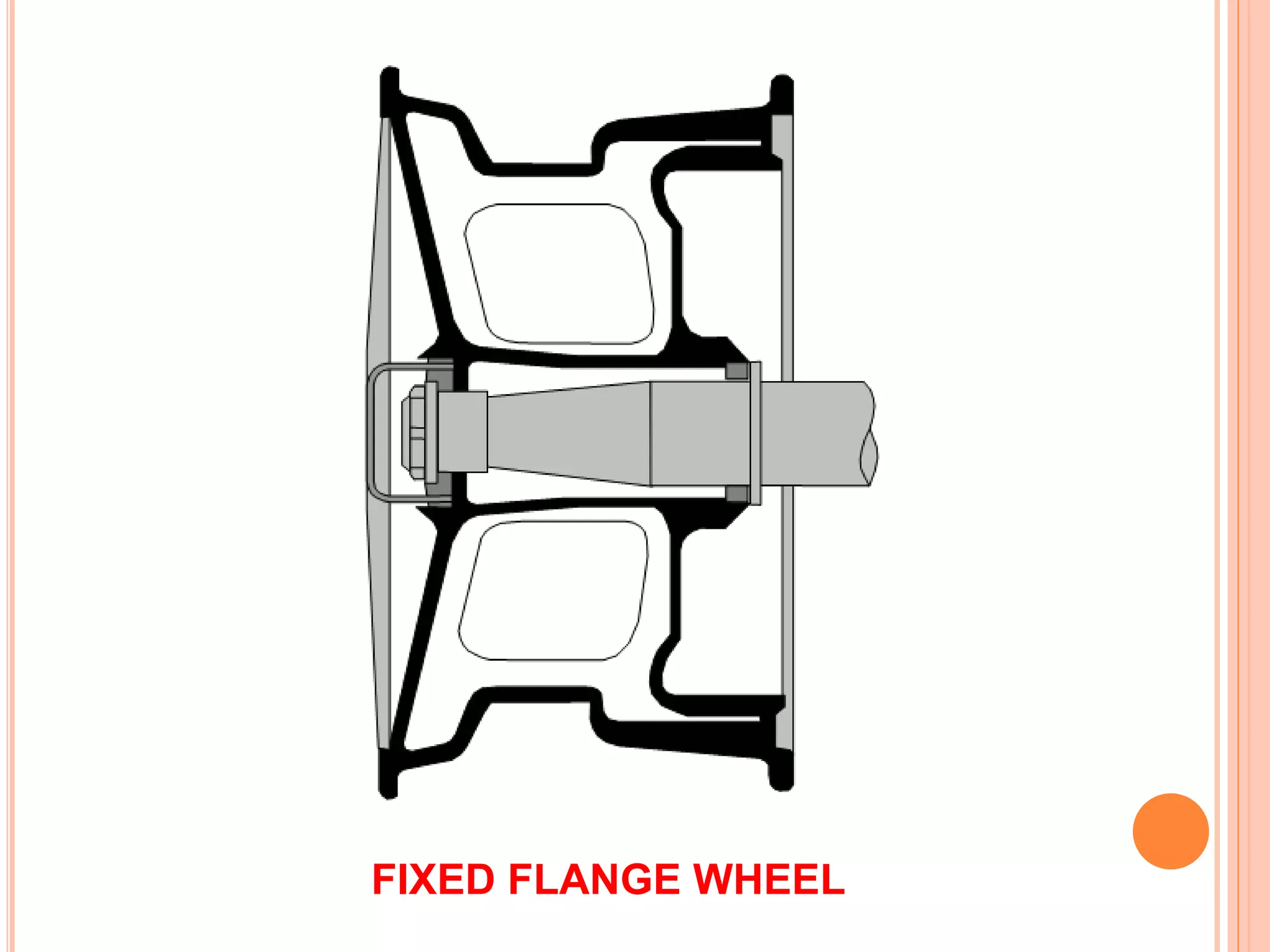
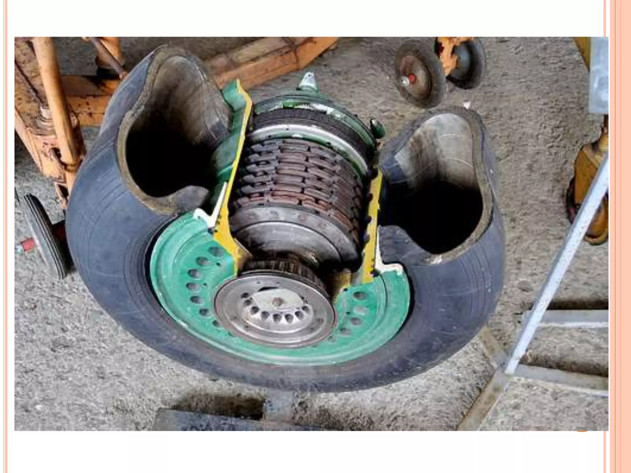
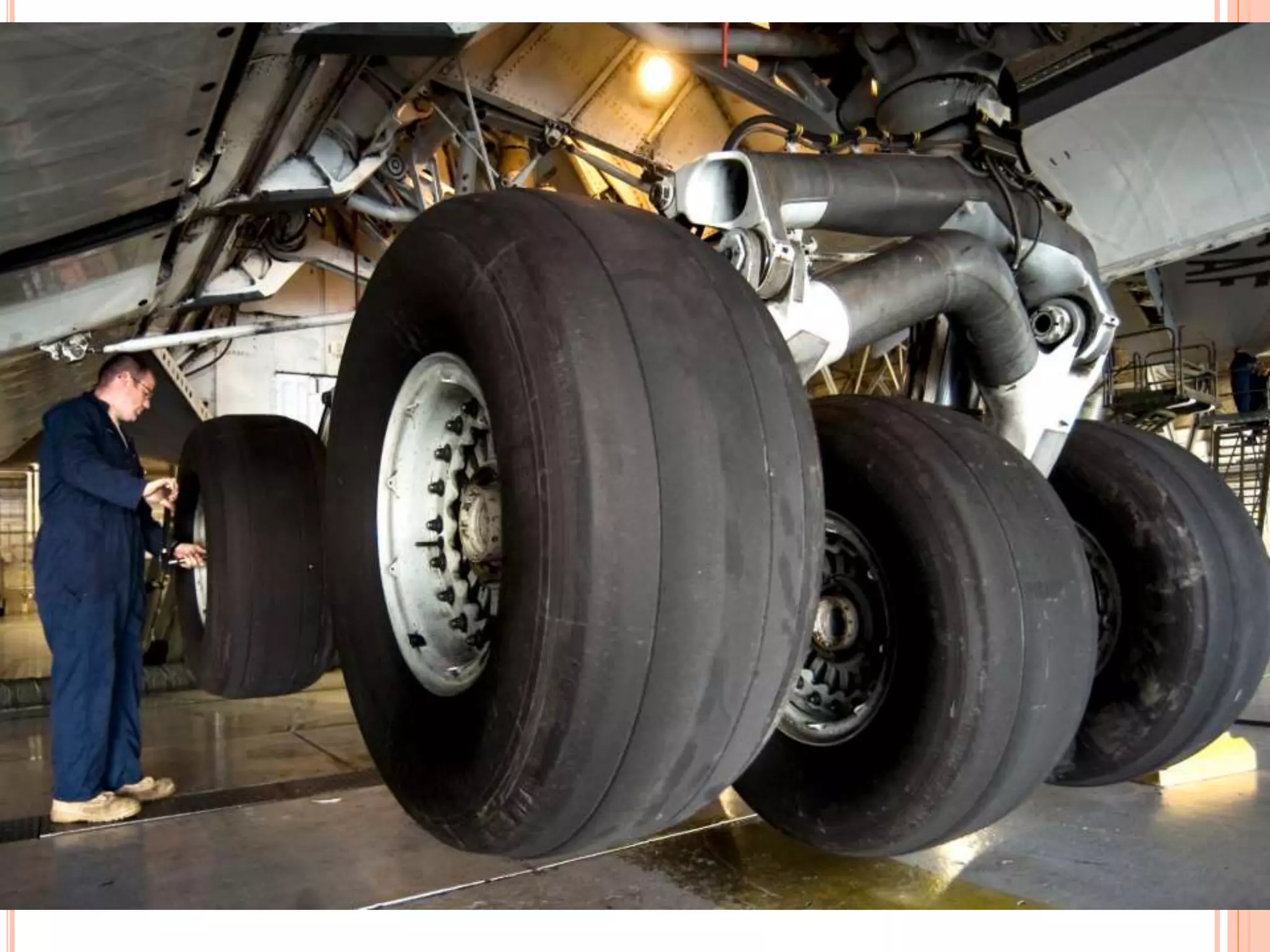
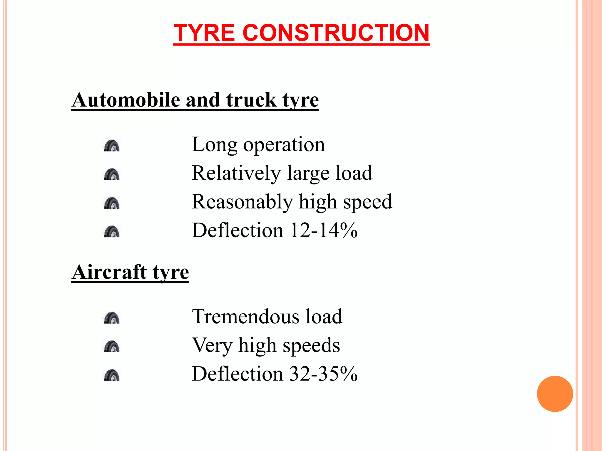
Aircraft wheels are an important component of a
landing gear system.
With tires mounted upon them, they support the
entire weight of the aircraft during taxi, takeoff, and
landing.
The typical aircraft wheel is lightweight, strong, and
made from aluminum alloy.
Some magnesium alloy wheels also exist.
Early aircraft wheels were of single piece
construction, much the same as the modern
automobile wheel.
AIRCRAFT WHEELS
As aircraft tires were improved for the
purpose they serve, they were made stiffer
to better absorb the forces of landing
without blowing out or separating from the
rim.
Stretching such a tire over a single piece
wheel rim was not possible.
A two-piece wheel was developed.
AIRCRAFT WHEELS
Early two-piece aircraft wheels were
essentially one-piece wheels with a
removable rim to allow mounting access for
the tire.
These are still found on older aircraft. Later,
wheels with two nearly symmetrical halves
were developed.
Nearly all modern aircraft wheels are of this
two piece construction.
Features of a two
piece aircraft wheel
found on a modern
airliner
WHEEL CONSTRUCTION
The typical modern two-piece aircraft wheel
is cast or forged from aluminum or
magnesium alloy.
The halves are bolted together and contain a
groove at the mating surface for an o-ring,
which seals the rim since most modern
aircraft utilize tubeless tires.
The bead seat area of a wheel is where the
tire actually contacts the wheel.
WHEEL CONSTRUCTION
It is the critical area that accepts the
significant tensile loads from the tire
during landing.
To strengthen this area during
manufacturing, the bead seat area is
typically rolled to pre stress it with a
compressive stress load.
WHEEL CONSTRUCTION
Modern tyres are much more rigid, due to
the load bearing requirements, which
results in the wheels having to be of two
piece construction .
The two piece wheel construction, are of 2
types, removable rim or split wheel.
INBOARD WHEEL HALF
Wheel halves are not identical.
The primary reason for this is that the inboard
wheel half must have a means for accepting
and driving the rotor(s) of the aircraft brakes
that are mounted on both main wheels.
Tangs on the rotor are fitted into steel
reinforced keyways on many wheels.
Other wheels have steel keys bolted to the
inner wheel halves.
INBOARD WHEEL HALF
These are made to fit slots in the perimeter
of the brake rotor.
Some small aircraft wheels have
provisions for bolting the brake rotor to the
inner wheel half.
Regardless, the inner wheel half is
distinguishable from the outer wheel half
by its brake mounting feature.
Keys on the inner wheel half of an aircraft wheel used to engage
and rotate the rotors of a disc brake
Both wheel halves contain a bearing cavity formed into the
center that accepts the polished steel bearing cup, tapered
roller bearing, and grease retainer of a typical wheel
bearing set-up.
A groove may also be machined to accept a retaining clip to
hold the bearing assembly in place when the wheel
assembly is removed.
The wheel bearings are a very important part of the wheel
assembly.
The inner wheel half of a wheel used on a high
performance aircraft is likely to have one or more thermal
plugs.
Heavy use of the
aircraft brakes can
cause tire air
temperature and
pressure to rise to a
level resulting in
explosion of the wheel
assembly.
To alleviate this,
thermal plug(s)
mounted in the inner
wheel half of a high
performance aircraft
wheels are made with a
fusible core that melts
and releases the air
from the
tire before explosion.
During heavy braking, temperatures can become so
great that tire temperature and pressure rise to a level
resulting in explosion of the wheel and tire assembly.
The thermal plug core is filled with a low melting point
alloy.
Before tire and wheel temperatures reach the point of
explosion, the core melts and deflates the tire.
The tire must be removed from service and the wheel
must be inspected in accordance with the wheel
manufacturer’s instructions before return to service if a
thermal plug melts.
Adjacent wheel assemblies should also be
inspected for signs of damage.
A heat shield is commonly installed under
the inserts designed to engage the brake
rotor to assist in protecting the wheel and
tire assembly from overheating.
An over inflation safety plug may also be
installed in the inner wheel half.
This is designed to rupture and release
all of the air in the tire should it be over
inflated.
The fill valve is also often installed in the
inner wheel half with the stem extending
through holes in the outer wheel half to
permit access for inflation and deflation.
OUTBOARD WHEEL HALF
The outboard wheel half bolts to the inboard
wheel half to make up the wheel assembly upon
which the tire is mounted.
The center boss is constructed to receive a
bearing cup and bearing assembly as it does on
the inboard wheel half.
The outer bearing and end of the axle is capped
to prevent contaminants from entering this area.
Features of a two
piece aircraft wheel
found on a modern
airliner
OUTBOARD WHEEL HALF
The outboard wheel half provides a convenient
location of the valve stem used to inflate and
deflate tubeless tires.
Alternately, it may contain a hole through which
a valve stem extension may pass from the inner
wheel half or the valve stem itself may fit
through such a hole if a tube-type tire is used.
WHEEL INSPECTION
An aircraft wheel assembly is inspected
while on the aircraft as often as possible.
A more detailed inspection and any
testing or repairs may be accomplished
with the wheel assembly removed from
the aircraft.
ON AIRCRAFT INSPECTION
The general condition of the aircraft
wheel assemblies can be inspected while
on the aircraft.
Any signs of suspected damage that may
require removal of the wheel assembly
from the aircraft should be investigated.
PROPER INSTALLATION
The landing gear area is such a hostile environment that
the technician should inspect the landing gear including the
wheels, tires and brakes whenever possible.
Proper installation of the wheels should not be taken for
granted.
All wheel tie bolts and nuts must be in place and secure.
A missing bolt is grounds for removal and a thorough
inspection of the wheel halves in accordance with the
wheel manufacturer’s procedures must be performed due
to the stresses that may have occurred.
PROPER INSTALLATION
The wheel hub dust cap and anti-skid sensor
should also be secure.
The inboard wheel half should interface with the
brake rotor with no signs of chafing or excessive
movement.
All brake keys on the wheel must be present and
secure.
Examine the wheels for cracks, flaked paint and
any evidence of overheating.
Inspect thermal plugs to ensure no sign of the
fusible alloy having been melted.
PROPER INSTALLATION
Thermal plugs that have permitted pressure loss in
the tire require that the wheel assembly be
removed for inspection.
All other wheels with brakes and thermal plugs
should be inspected closely while on the aircraft to
determine if they too have overheated.
Each wheel should be observed overall to ensure it
is not abnormally tilted.
Flanges should not be missing any pieces, and
there should be no areas on the wheel that show
significant impact damage.
PROPER INSTALLATION
The removable rim wheel has an inner tube
where as the split wheel is tubeless and requires
a perfect seal between the halves.
An O ring is located between the mating
surfaces.
To be as light and strong as possible they are
usually constructed from alluminium or
magnesium alloys and may be cast or forged.
The inboard wheel section is fitted with key ways that
allows the brake discs to slot into.
These key ways drive the brake discs with the wheels.
Larger aircraft wheels have one or more fusible plugs
fitted.
These plugs have a centre hole which is filled with a
low melting point alloy.
In the event of the tyre overheating, when a
temperature limit is reached the low melting point alloy
melts and allows the tyre to safely deflate.
AXLE NUT TORQUE
Axle nut torque is of extreme importance on an
aircraft wheel installation.
If the nut is too loose, the bearing and wheel
assembly may have excessive movement.
The bearing cup(s) could loosen and spin,
which could damage the wheel.
There could also be impact damage from the
bearing rollers which leads to bearing failure.
Improper loose torque on the axle nut can cause excessive end
play leading to bearing race damage known as scalloping.
Eventually, this leads to bearing failure.
AXLE NUT TORQUE
An over-torqued axle nut prevents the bearing
from properly accepting the weight load of the
aircraft.
The bearing spins without sufficient lubrication
to absorb the heat caused by the higher friction
level.
This too leads to bearing failure.
All aircraft axle nuts must be installed and
torqued in accordance with the airframe
manufacturer’s maintenance procedures.
TYPES OF WHEELS
There are three basic types of wheel
used for aircraft:
Well-based
Divided (or Split)
Loose and Detachable Flange
WELL-BASED
This type is limited to smaller
light aircraft and is similar to
those found on a typical family
car.
DIVIDED (OR SPLIT)
This type is used on most modern
commercial airliners.
It consists two half assemblies matched
up and bolted together to form the
complete wheel.
Each half is more or less identical and
has its own tapered bearing assembly.
DIVIDED (OR SPLIT)
A sealing ring is incorporated between the
two halves, to provide an airtight joint when
the wheel is used with a tubeless tyre.
Additionally, the inner half will carry the
brake rotor drive blocks and the outer half
may be fitted with fusible plugs.
LOOSE AND DETACHABLE FLANGE
This type of wheel has a main hub, which carries both
bearings, brake rotor drive blocks and fusible plugs.
To facilitate tyre replacement, one of the two wheel
flanges can be removed.
The flange when refitted to the wheel hub is retained
by a locking ring (loose flange) or by means of a
series of nuts and bolts (detachable flange).
As with the divided wheel a sealing ring is
incorporated in the flange recess to provide the
airtight joint when used with tubeless tyres.
An Aircraft tyre carries 250 to
1,000 times its mass compared
to 50 times for a passenger car
tyre, while aircraft tyre
temperatures can fall to -50 ˚
during flight and reach + 60 ˚ on
the runway
ROLLING ON TIRES
1736 - natural rubber is developed from South
American threes, presenting good rubbing of
pencil marks (hence “rubber”)
1887 - pneumatic tire developed by John Boyd
Dunlop for son bicycle
Vulcanization of natural rubber is credited to
Charles Goodyear & Robert William Thomson
1920 - Synthetic rubbers by Bayer
Today - over 1 billion produced over 400 tire
factories
- Many A/C tires and inner tubes are still
made of natural rubber due to the high cost of
certification for A/C use of synthetic
replacements
- rubber delivered from petroleum
Latex being collected
from a tapped rubber tree
Airless tire
A/C tire maintenance at
sea aboard
USS Abraham Lincoln
A blown-up tire
FE analysis of A/C tire
Dunlop
Goodyear
Bridgestone
Michelin
Condor
Specialty Tires
INTERNATIONAL AIRCRAFT TYRE
MAKERS
TYRES
Tyres with patterned tread became important when
aircraft got effective brakes that could be used for
slowing the aircraft during landing.
At first the treads were a diamond pattern that
provided good braking on wet grass but the ribbed
tread proved to be more suitable for operation on
hard surface runways.
Today almost all aircraft tyres have a ribbed tread
that consists of straight grooves, which run around
the tyres’ circumference.
Bogie type design
for runway load reduction
Bomber XB-36 – 9’ DIA circa 1946 Spoke wheel type tire – WWI era
Cargo type A/C
Antonov 225 landing gear
heavy loads, high speeds and high deflections
HEAT
RUBBER
(good insulator)
reduce the tire life
Traction waves
groove cracing
rib undercutting
tread separation
CENTRIFUGAL
FORCES
taxi speed – inflation pressure – taxi distance
Internal tensile forces
on each layer
carcass separation
TENSILE
COMPRESSION
SHEAR FORCES
Automobile and truck tyre
Long operation
Relatively large load
Reasonably high speed
Deflection 12-14%
Aircraft tyre
Tremendous load
Very high speeds
Deflection 32-35%
TYRE CONSTRUCTION
TYRE INFLATION AND
DEFLATION
The tyres are inflated with nitrogen from a
ground cart.
The required pressure will be laid down in
the AMM and a tyre inflation box is used to
regulate the charge rate and pressure.
A deflation tool is used to release the
pressure and any ice that forms must be
allowed to thaw before the valve core is
removed.
WHAT IS NITROGEN?
Nitrogen is a dry, inert gas used to inflate airplane tires, off-
road truck tires, military vehicle tires, and race car tires for
improved performance, more tire mileage and better fuel
economy.
Why use Nitrogen?
Less inflation pressure loss
Reduced wheel corrosion
Prevents inner-liner rubber deterioration by oxidation
Tires run cooler
Increases tread life
Increases fuel mileage
Helps prevent uneven wear
Oxygen in compressed air permeates through the wall of
the tire, thus reducing the tire's inflation pressure.
During it's journey through the tire wall, oxygen oxidizes
the rubber compounds in the tire, causing under-inflation
and deterioration of the rubber .
Dry nitrogen will maintain proper inflation pressure and
will prevent auto-ignition, will not corrode rims, extends
valve core life and will help the tire to run cooler.
The biggest advantages - improved tire life
Experts in the tire industry indicate that oxidative aging
is one of the primary causes of decreased tire life.
Oxidative aging is caused by the diffusion of oxygen
from the pressurized air cavity of the tire to the outside
atmosphere.
Tests have shown that if tires are inflated with nitrogen,
there is a significant reduction in tire failure.
Oxygen and moisture corrodes aluminum and steel wheels.
Oxygen also reacts with rubber, another type of "corrosion".
When this corrosion starts, the small particles break off and form
rust and dust, which can clog vavle cores, causing them to leak.
The rough surfaces created from the corrosive action on the
wheels leads to tire beads that don't seal properly, causing
additional leaks.
Oxygen also ages the inner liner, the thin layer of rubber inside
the tire whose function is to keep air away from the carcass.
As the inner liner ages, more and more air molecules can pass
through it, causing more pressure losses.
These pressure losses in a truck tire can average 2 psi a month
as a result of the air passing through the sidewalls.
As it passes through the rubber, the oxygen can also corrode the
steel cords, causing them to rust too.
THE BEAD
The bead gives the tyre its strength
and stiffness to assure a firm mounting
on the wheel.
The bead is made up of bundles of
high strength carbon steel wire with
two or three bead bundles on each
side of the tyre.
THE BEAD
Rubber strips streamline the round bead
bundles to allow the fabric to fit smoothly
around them without any gaps.
The bead bundles are enclosed in layers of
rubberised fabric, to insulate the carcass
plies from the heat absorbed in the bead
wires.
THE CARCASS
The carcass (or chord body) is the body of
the tyre that is made up of layers of
rubberised fabric cut in strips with the
threads running at an angle of about 45
degrees to the length of the strip.
These strips extend completely across the
tyre around the bead and partially up the
side.
THE CARCASS
Each ply is put on in such a way that the
threads cross each other at about 90
degrees to that of the adjacent ply.
This type of construction is known as bias
ply.
The cords of the ply fabric were originally
cotton, then nylon and now aramid fibres
(kevlar) are used.
THE CARCASS
This is stronger than nylon, polyester or
fibreglass and even strong pound for pound
than steel.
Chafing strips are rubberised strips of fabric
that wrap around the edges of the carcass
plies and enclose the bead area.
The chafing strips provide a smooth chafe
resistant surface between the tyre and the
bead seat of the wheel.
THE CARCASS
The under tread is a layer of compound
rubber between the plies and the tread
rubber that provides good adhesion
between the tread and the carcass.
On top of the under tread are more plies of
strong fabric that strengthen the tread and
oppose centrifugal forces that try to pull the
tread from the carcass during high speed
rotation.
THE CARCASS
The inner liner is a thin coating of rubber over
the inside plies.
For tubeless tyres it is made from a compound
which is less permeable than other rubbers
used.
It seals the tyre and reduces the amount of
leakage.
On tyres with inner tubes the liner is very
smooth to help prevent chafing.
THE TREAD
The tread is the thick layered rubber
around the outer circumference of the tyre
that serves as a wearing surface.
The tread has a series of moulded
grooves moulded into its surface to give
optimum traction with the runway surface.
A/C TIRE MAINTENANCE/OPERATION
PPE equipment
Storage/Protection of tires
- Bright sunlight
- Excessive heat
- temperature: cold (flat spot)
- Oil, fuel, hydraulic fluid, etc.
- ozone: electric motor, welding sparks
Inspection of tires
Special: FOD, hard landing, under
inflation (-95%),
wear
Tire defects
- ozone cracking (degradation)
- break burns
- skid burns
- hydroplaning
TYRE WEAR ASSESSMENT
The manner in which tread wear of a tyre is
established, is dependent upon which of a
number of methods of indicating wear has
been incorporated into the tyre by the
manufacturer.
Tyres used on modern aircraft have a series
of circumferential grooves in the tread,
primarily to displace water on the runway
and so help to prevent the tyre from
aquaplaning.
TYRE WEAR ASSESSMENT
These grooves can be also used as a
means of establishing tyre wear.
If this method is adopted, then wear which
results in any groove being less than 2mm
in depth, for more than 25% of the tread
circumference, requires the tyre to be
replaced.
TYRE WEAR ASSESSMENT
Other ways of establishing wear
assessment are by the use of:
Tie Bars
Wear indicator Grooves
Sipes
TIE BARS
These are small transverse bars of rubber,
moulded at intervals in the circumferential
grooves around the tyre as described above.
They are set at a depth of 2mm, or as
required by the particular manufacture and
thus provide an easy visual means of
establishing wear limits.
Limits – tyre worn to the top of the tie bar.
WEAR INDICATOR GROOVES
These are dedicated grooves set in the
tread pattern and have a depth graduated
by the manufacturer, but typically 2mm
shallower than the water-displacing
grooves.
Limits – tyre worn to the bottom of the
indicator groove anywhere on the
circumference of the tyre.
SIPES
Certain tyres, normally those having a
zigzag tread pattern have an axial slit in the
tread rubber at some of the zigzag corners.
The slit does not extend into the depth of
the tread and is called a sipe.
Limits – Tyre worn to the bottom of the
sipe.
TYRE DAMAGE
The amount of tyre damage a tyre can suffer
without becoming unserviceable is very small.
Damage in the vicinity of the bead is rarely
tolerated.
While cuts in the casing plies must be assessed
very carefully in accordance with the
manufacturer’s requirements before deciding
on the degree of serviceability.
TYRE DAMAGE
Normally if the chords are exposed due any
form of damage, including splits or crazing,
then the tyre will be classed as
unserviceable.
NOTE: Always consult the
Aircraft/Component Maintenance Manual.
LEAK HOLES (AWL HOLES)
During inflation of a tyre/tube assembly, air
may become trapped between the tube and
the inside surface of the tyre, giving an
incorrectly inflated assembly.
The risk is reduced by allowing the air to
escape through Leak Holes, pierced
completely through the sidewall of the tyre,
during manufacture.
LEAK HOLES (AWL HOLES)
The holes are often made with a pointed
tool called an Awl.
Because of this, the holes are sometimes
referred to as Awl Holes.
The position of these holes is indicated by a
series of 6mm diameter spots of grey or
green litho ink, usually grey.
VENT HOLES
During the manufacture of tubeless tyres,
air that gets trapped between layers in the
casing is permitted to escape to
atmosphere through vent holes pierced in
the sidewall.
The vent holes do not penetrate right
through the sidewall in this case and are
identified, as with leak holes, by 6mm
diameter spots of grey or green litho ink,
usually green.
BALANCE MARKS
A red spot (sometimes triangular) on either side of
the tyre indicates its lightest point around the
circumference as ascertained during the
manufacturer’s balancing procedure.
During assembly with the wheel the red spot should
be aligned with the inflation valve on a tubeless
assembly.
On a tubed assembly, the spot should be aligned with
a red line (heavy point) on the tube.
If it has no red line, align with the inflation valve of the
tube.
ELECTRICALLY CONDUCTING
TYRES
Some wheel assemblies are fitted with tyres
that are designed to conduct electrical
charges to earth as the aircraft touches
down.
Such tyres are identified with the word
CONDUCTIVE or the letters ECTA
(electrically conducting tyre assembly) on
the sidewall.
AQUAPLANING
Aquaplaning is a condition that occurs on
wet runways when a wave of water builds
up in front of a spinning wheel.
This could result in the tyre being lifted from
the runway surface and to float on the thin
layer of water.
This is dangerous, as a complete loss of
braking efficiency will occur.
AQUAPLANING
Although it appears only to be an aircrew
problem, there is a significant factor that
affects the maintenance engineer.
Mathematically there is a formula for
Aquaplaning speed -
Aquaplaning Speed (Kt.) = 9 (approx.) x
Square Root
of the Tyre
Pressure.
AQUA PLANING
This speed will be placard for the crew, so
that in wet conditions they will quickly traverse
through it on landing.
However, if the tyre pressures are incorrect,
the placard speed will be useless and
aquaplaning will occur at a different speed.
Take care, therefore, to maintain tyre
pressures at their correct value at all times.