
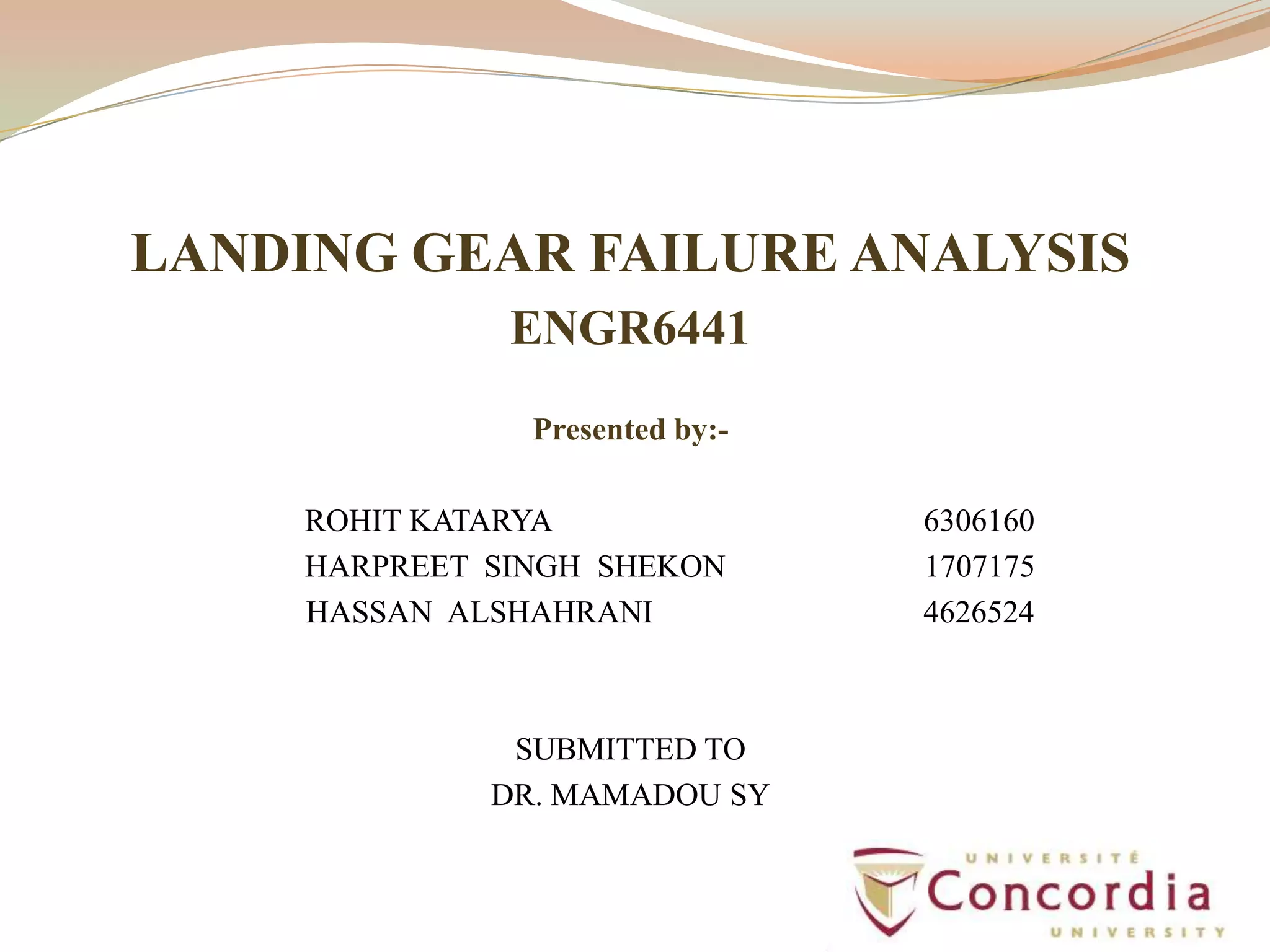
![Failure Mechanisms of Landing gear
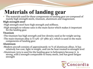
Fatigue Cracking Failure
Usually aircrafts and military experience serious damages and the fatigue.
Equations used for analyzing:
(1)Paris equation:
da/dN=C(∆K)n
(2) Forman equation:
da/dN = C[(∆K)]n/[(1-R) Kcr-∆K]
(3)Walker Equation:
Effective Stress= (1-R) m x Maximum Stress](https://image.slidesharecdn.com/finalengr6441presentationlandinggear-130521044852-phpapp02/85/Landing-gear-Failure-analysis-of-an-aircraft-6-320.jpg)

![REFERENCES
[1] http://www.seawindpilots.com/landing_gear.htm
[2] http://www.tms.org/pubs/journals/JOM/1005/boyer-1005.html
[3] http://www.bucanada.ca/blanking_hss.htm
[4] http://www.materialsengineer.com/CA-Creep-Stress-Rupture.htm
[5] F.C. Campbell: “Manufacturing Technology for Aerospace Structural
Materials,” First Edition, Elsevier ltd, Chapter 4, pg 125-168, 2006
[6] http://en.wikipedia.org/wiki/7075_aluminium_alloy
[7] http://www.substech.com/dokuwiki/doku.php?id=fracture_toughness
[8] http://www.materialsengineer.com/CA-ductbrit.htm
[9]http://www.sv.vt.edu/classes/MSE2094_NoteBook/97ClassProj/exper/b
allard/www/ballard.html
[10] http://www.lambdatechs.com/publications/all-technical-papers.html
[11] Handbook of Case Histories in Failure Analysis, Vol. 1 and 2, Esaklul Ed.
[12] ASM Handbook, Vol.12, Fractography, ASM International, Materials
Park, 1992
[13] Handbook of case histories in failure analysis, Volume 2By
KhlefaAlarbeEsaklul, ASM International, Page no. 13
](https://image.slidesharecdn.com/finalengr6441presentationlandinggear-130521044852-phpapp02/85/Landing-gear-Failure-analysis-of-an-aircraft-16-320.jpg)
![ [14] Aviation safety investigations & reports, , Boeing B747-300 aircraft, JA 8184 at Sydney Aero.
Investigation Number:200502400.
[15]http://www.atsb.gov.au/publications/investigation_reports/2005/aair/aair200502400.aspx”
[16] . V. Horak, “Advanced Landing Gear Fatigue Test Method,” in LMS conference Europe,
Prague, 23-26 march, 2006.
[17]. W. Krason and J. Malachwoski, “Effort Analysis of the Landing Gear With Possible Flow During
Touchdown,” International Journal of mechanics, issue 1, volume 2, 2008.
[18].FAR–23: Airworthiness Standards, Normal, Utility, Acrobatic and Commuter Category Airplanes,
1966.
[19] .J.O. Hallquist, LS-Dyna. Theoretical manual. California Livermore Software Technology
Corporation, 2005.
[20]ASM Handbook, Vol. 11, Failure Analysis and Prevention, ASM International, Materials Park,
1992
[21] Currey, Norman S. Aircraft landing gear design : principles and practices American Institute of
Aeronautics and Astronautics, 1988
[22]https://intra.techniek.hva.nl/AVI/0708/Jaar2/VLS5_21/Studiemateriaal/VLS_LandingGear.pdf
[23] Moir, I., and Seabridge, A., Aircraft Systems: Mechanical, Electrical, and Avionics Subsystems
Integration, AIAA Education Series, AIAA, Reston, VA,2001.
[24] Hoblit, F. M., Loads on Aircraft: Concepts and Applications, AIAA Education Series, AIAA,
Washington, DC, 1988.
[25] http://www.mts.com/en/products/application/aerospace/components/landing-gear/index.htm
[26] Shultz, Peter. and Lynn K. G., “Interaction of Positron Beams with Surfaces, Thin Films, and
Interfaces,” Reviewsof Modern Physics, Vol. 60, No. 3 July 1988
[27] New Techniques for Detecting Early Fatigue Damage Accumulation in Aircraft Structural
Components, Curtis A. Ride out, Scott J. Ritchie, Positron Systems, Inc.,411 S. Fifth St., Boise, ID
83702”
[28] BOEING’S SAFETY ASSESSMENT PROCESSES FOR COMMERCIAL.”Jeff Hasson
Boeing Commercial Airplane Group:.” David CrottyScitor Corporation AIRPLANE DESIGNS](https://image.slidesharecdn.com/finalengr6441presentationlandinggear-130521044852-phpapp02/85/Landing-gear-Failure-analysis-of-an-aircraft-17-320.jpg)


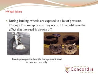
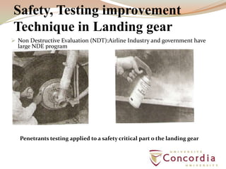
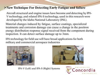
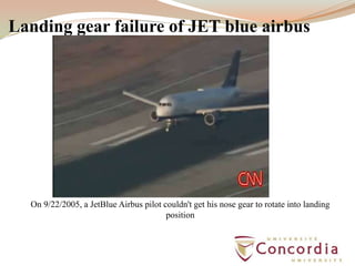
The document analyzes potential failures of aircraft landing gear components. It discusses the main eight components of landing gear, including locks, retraction systems, brakes, wheels, and struts. Failure mechanisms like fatigue cracking, stress corrosion cracking, and dynamic failure during landing are examined. The materials used for landing gear like high-strength steels, titanium, aluminum, and magnesium alloys are also summarized. Non-destructive testing and new techniques for early fatigue detection are reviewed as ways to improve landing gear safety and maintenance.


