1. Types of
foundation
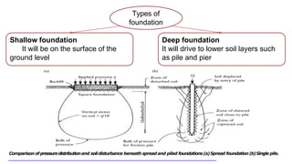
Shallow foundation
It will be on the surface of the
ground level
Deep foundation
It will drive to lower soil layers such
as pile and pier
3
Comparison ofpressuredistributionand soildisturbance beneath spread and piled foundations(a)Spread foundation(b)Single pile.
2. Pile
foundations
Pile is a Column driven into the
soil to support a structure by
transferring the building loads
to the deeper and stronger layer
of soil or rock, and supported by
a combination of skin friction
and end bearing.
are commonly
constructed of timber,
concrete, steel and
composite
4
3. The upper
soil layer is
too weak
Bedrock is
not
encountered
at a
reasonable
depth
Subjected to
horizontal
forces
5
Although the use of pile foundation cost more than shallow
foundation, it is combination of skin friction essential to be
employed for some conditions. Such Conditions Are
Enumerated
Expansive &
collapsible
soils extend
to a great
depth below
the ground
surface
Foundations
below the
water table
are
subjected to
uplifting
forces
Bridge
abutments
and piers are
to avoid the
possible loss
of bearing
capacity
4. Soft to
Firm Clay
Large Distributed
Weight
Very Large Concentrated
Weight
Strong Rock
Low
Weight
5. All theloads from thesuper structure like,
- Live loads
- Dead loads
- Wind loads
- Seismicload
Theloadsfromthesurroundingsoilincaseof seismicevent.
Waterloadsincaseof off-shore structure.
7. Is an ideal material for piling. It has a high
strength to weight ratio, it is easy to handle,
it is readily cut to length and trimmed after
driving.
TIMBER
PILES
Timber piles have three types according to the
American Society of Civil Engineers:
1) Class A, carry heavy loads, minimum
diameter of butt 356 mm.
1) Class B; carry medium loads, minimum
diameter of butt 305 mm to 330mm.
2) Class C piles are used for temporary
construction work, minimum diameter of but
305mm.
7
Timber Piles
8. Preparation of Timber Pile In
the Site
Timber piles cannot
withstand hard driving
stress, therefore ⇒
To avoid damage at the
bottom of timber piles, steel
shoes may be used
To avoid the damage to the
top of the piles, a metal
band or a cap may be used
8
Protectingtimberpiles fromsplitting duringdriving(a)Protecting
head by mild steelhoop (b)Protectingtoe by cast steel point.
Protecting timber piles from decay (a) By precast concrete
upper section above water level (b) By extending pile cap
below water level.
10. Advantages of
TimberPiles
Disadvantages
of TimberPiles
1. They can easily be extracted
2. They are economical in cost.
3. They can stay undamaged indefinitely if they are surrounded
by saturated soil.
1. Timber pile cannot withstand hard driving stress.
2. The pile capacity is generally limited.
3. Top of timber easy to damage during the driving operation.
4. Subject to attack by various organisms and insects.
10
11. PRECAST CONCRETE PILE
have their principal use in marine and river structures, i.e.
in situations where the use of driven and cast-in-place piles
is impracticable or uneconomical
Concrete
Piles
PrecastConcrete Piles, PrecastConcrete Piles,
13. 13
Unseenbreakage ofprecast concrete piles
withwelded buttjoints.
JOINTED PRECAST CONCRETE PILES
casting on additional lengths to accommodate variations in the depth to a hard bearing stratum
will be evident. These drawbacks can be overcome by employing jointed piles
Typical locking pin joint for precast concrete pile.
14. 1) Can be subjected to hard driving.
2) Corrosion resistant.
3) Can be easily combined with a concrete
superstructure.
1) Difficult to achieve proper cutoff.
2) Difficult to transport.
Advantages of Precast
Concrete Pile
Disadvantages of
Precast Concrete Piles
14
15. CAST-IN-PLACE CONCRETE PILES
Piles are built by making a hole in the ground and then filling it with
concrete. These piles may be divided to two: (a) cased (b) uncased.Both
types may have a pedestal at the bottom
15
Cast in place concrete pile Cast in place concrete pile
top view of a cast-in-place pile
16. 16
Bulb Pile: They are special
forms of cast-in-place concrete
piles. It forms a large base (bulb)
during the driving process
increases their effectiveness in
serving as an end bearing pile.
Bulb Pile
Refe
SHELLTYPESCAST-IN-PLACEP
IL
ES
consistof a permanent lightgauge steel tube in
diameters from150to500mmwithwall thickness
up to6mmand are internally bottom driven by
drop hammer.
On reaching thebearing layer thehammer is
removed, any reinforcement inserted, and a
high slumpconcrete placed toproduce the pile.
The Taper Tube pile
17. Disadvantages of Cast-In-
Place Concrete Piles
1) Relatively low cost.
2) Allow for inspection before pouring
concrete.
3) Easy of length variation.
4) Minimal ground vibrations during
installation.
1) The uncertainty of the shape and condition of
the constructed pile.
2) The cast components may be damaged during
driving.
3) Difficult to splice after concreting.
4) Steel casings (temporary or permanently) and
reinforcing cages may also be required.
5) Cast-in-place concrete pile lengths are limited
by the drilling equipment used.
18
Advantages of Precast
Concrete Pile
18. Steel piles
are either pipe pile or rolled section steel H- section
piles.
Wide-flange and I-section steel beams can also be used as piles.
19
H-section piles are usuallypreferred because theirweb and flange
thicknessare equal.
Pipe pile can be driven into the ground with their ends open or close.
Figure 20: shapes of steel piles (a) and (b) Placing of Steel piles in site
19. Advantages of Steel
Piles
Disadvantages of
Steel Piles
1) Easy to handle with respect to cutoff and
extension to the desired length.
2) Can stand high driving stresses.
3) Can penetrate hard layers such as dense
gravel and soft rock.
4) High load-carrying capacity.
1) Steel Piles subject to corrosion.
2) They are very expensive.
3) High level of noise during pile driving.
4) H-section may be damaged or deflected from
the vertical during driving through hard layers
or past major obstruction.
21
20. Composite
pile
combinations of bored piles with driven piles can be
used to overcome problems resulting from particular
site or ground conditions such as the problem of
timber piles above ground-water level
composite piles may be made of steel and concrete or timber
and concrete.
Steel and concrete piles consist of a lower portion of steel
and an upper portion of cast-in-place concrete
composite piles are not economical compared with those of
uniform section
22
different stages in construction of composite piles
21. LARGE DIAMETER
BORED CAST-IN-
PLACE PILES
Large boreholes from 750mm up to 3m
diameter (with 7m under-reams) are possible
by using rotary drilling machinery. The
angering plant is usually crane or lorry
mounted.
Large diameter cast in place piles’machine
Stages of constructing large diameter bored cast-in-place piles
25
22. GROUT- OR
CONCRETE-
INTRUDED
PILES
The use of continuous flight augers is becoming a
much more popular method in pile construction.
These piles offer considerable environmental
advantages during construction
Their noise and vibration levels are low and there is
no need for temporary borehole wall casing or
bentonite slurry making it suitable for both clays
and granular soils
The only problem is that they are limited in depth to
the maximum length of the auger (about 25m)
Figure 31: Concrete
intruded piles
27
23. SHEET PILES
Sheet piles are structural tools which are designed to resist
horizontal forces as they embedded in soils. They are also
used as retaining systems.
Sheet piles are made of different materials as wood,
concrete, steel or aluminum which play an important role in
their applications
Sheet piles are widely used for several purposes
such as:
1) Large and waterfront structures
2) Erosion protection
3) Stabilizing ground slopes
4) Shoring walls of trenches and other
excavations, and cofferdams.
28
Installed sheet piles in a project common shapes of sheet piles
Reference: http://www.pennarindia.com/steel-products-sheet-piling.html
24. I. Load bearing piles
I . Non-load bearing piles
I. Load bearing piles :-
Itbearstheloadcomingfromthe structure.
ThePilesaregenerallydriven vertical y orinnearvertical
position.
When a horizontal forces to be resisted, theinclinedpilesmay
be driven in an inclined position andsuchinclinedpilesare
termedthebatter piles
Loadbearingpilesaredivided into,
i. Bearing piles
i . Friction Piles
25. This piles penetrate to through the soft soil and their
bottoms rest on a hard bed. Thus, they are end bearing
pilesandact as columns or piers.
The softgroundthroughwhichthepilespassalso gives some
lateral support andthis increases the load car ying capacity
of thebearingpiles.
26. Transmit most of their
loads to the load
bearing layer(dense
sand or rock). Most of
the pile capacity
inferred from the end
bearing point.
28. When loose soil extends to a great depth, the piles are driven
up to such a depth that the frictional resistance
developed at the sides of the piles equals the load
coming on the piles.
Great care should be taken todeterminethefrictional
resistanceofferedbythesoilandsuitable factor of safety
should be provided inthe design.
31.
The center to center distance of successive piles is known as pile spacing.
It has to be careful y designed by considering the fol owing
factors,
1) Types of piles
2) Material of piles
3) Length of piles
4) Grouping of piles
5) Load coming on piles
6) Obstruction during pile driving
7) Nature of soil through which piles are passing.
The spacing between piles in a group can be assumed based
on the fol owing: 1- Friction piles need higher spacing than
bearing piles.
2- Minimum spacing (S) between
piles is 2.5. 3- Maximum spacing
(S) between piles is 8.0.
32. S
2 Piles 3 Piles S
4 Piles 5 Piles
S S
6 Piles
7 Piles
34. CHOICE OF PILE
MATERIALS
Timber is cheap relative to concrete or steel. It is
light, easy to handle, and readily trimmed to the
required length. It is very durable below ground-water
level but is liable to decay above this level.
Concrete is adaptable for a wide range of pile types. It
can be used in precast form in driven piles, or as
insertion units in bored piles.
Steel is more expensive than timber or concrete but
this disadvantage may be outweighed by the ease of
handling steel piles, by their ability to withstand hard
driving, by their resilience and strength in bending,
and their capability to carry heavy loads
29
35. 1) The depth to a stratum capable of supporting apile.
2) The availability of materials for piles.
3) The number of piles required.
4) The driving equipment.
5) The depth and kind of water if any, above the ground
which the piles will be driven.
6) Location and type of structure.
7) Types of structures adjacent to the site.
8) The size, weight of the structure.
9) The physical properties of the soil stratum on site.
10)The durability required.
11)The comparative in-place cost.
30
Factors Influencing
Choice Of Piles To Be
Used For Construction
36. PILE
HAMMERS
The available types include:
1) Drop.
2) Single-acting steam or compressed air
(60 blows per minute).
3) Double-acting steam or compressed
air (120 blows per minute).
4) Differential-acting steam or
compressed air ( Frequency usually
between single and double).
5) Diesel ( Can operate in freezing
weather, but may fail to operate in soft
soil).
6) Hydraulic.
7) Vibratory drivers ( most effective in
driving piles into granular soils, they
operate at very high frequencies).
Typical operation of pile driving hammers
31
37. Dropping weight
(Drop Hammer)
The dropping weight or drop
hammer is the most commonly used
method of insertion of displacement
piles.
Variants of the simple drop hammer are the single
acting and double acting hammers. These are
mechanically driven by steam, by compressed air
or hydraulically.
Piles' dropping weight in the
32
38. 33
Rapid controlled explosions can be produced by
the diesel hammer.
Diesel
Hammer
Using diesel hummer in the site
This type of hammer is most suitable for driving piles
through non-cohesive granular soils where the major
resistance is from the end bearing.
39. Vibratory methods of pile driving:
Vibratory methods can prove to be very effective in driving piles through non cohesive
granular soils. The vibration of the pile excites the soil grains adjacent to the pile
making the soil almost free flowing thus significantly reducing friction along the pile
shaft.
Jacking methods of insertion:
Jacked piles are most commonly used in underpinning existing
structures. By excavating underneath a structure short lengths of
pile can be inserted and jacked into the ground using the underside
of the existing structure as a reaction.
jacking method of insertion
34