1. ---<-)
/"'
PNEUMATIC SIIKIIqG - A CASE STUDY
''B! ',:,
:.'.',1, :,.....:
'; .. .:. .r, :.,
Dmneu*
1. INTRODUCTION
Pneumatic caisson are used in
preference to open well caisson in
situations where dredging from opsn well
would cause loss of ground around
caisson, soil underneath is full of boulder
or clay soil which poses problems for
sinking the well, This technique is used for
all types of soil in case of bridges where
progress of sinJring by conventional method
is very slow. Though this method is costlier,
it gives higher output compared to
conventional sinking.
Pneumattc sinking technique is used
to force out the water inside the well to get
almost water free area where msn can
work inside the working chamber and take
out material to expedite the sinking of the
well.
Pneumatic sinking has following
advantages over conventional methods:
(a) The work is done in dry condition and therefore,
control over the work on foundation is better.
(b) Plumbness of caisson is easy to control as
compared to open calsson.
(c) Obstructions like boulders and loqs can be
removed. Excavation by blastini rnay be
done, if necessary.
(d) Bottom plugging can be effectively done in
pneumatic condition.
The main constraint in pneumatic
sinJring is restriclion of working period"
Hours of works for workmen, who zte
subjected to compre s sion and
decompression, shall not be more than
specified below in any consecutive 24
hous (IS: 4138-1971).
Pressure in Kg/crn2 Number of hours
execluding the period of
comprsssion and
decompression
Min. Max.
0
1.25
2.20
1.25
2,20
3.40
I
6
4
2. ESSENTIAL FAR.T AND TECHNECAL
SPECIFICATION OF PNETMATIC
CAISSON
2.1. Workittg Charnber
The working chamber is the space at
the bottom of pneumatic caisson surrotrnded
by the bevelled wall of cutting edge anci
roof by steel diaphragm or concrete plug
(corbel slab). Since it is the space for the
workmen to excavate the soil, it should be
at leastZ,S m high. The side wall and roof
are designed to withstand the maximum
anticipated air pressure. This air pressure
in general is slightly greater than the
pressure due to the head of water above
the bottom of caisson.
* Assistant Director (Bridges), HQ DGBR (Br Dte) West Block-IV, wing No. 1 (GD, R.K. puram, New Delhi
INDIAN HIGFIWAYS, FEBRUARY 1996
*- i'L i.i.,F- i,' i;ir{A Yt'-f '*6'-'' U ot,
-,"""}i--O-t i u*..-'q-gi.ilt'." j-€-yYi*i,"o* , lr,,n,
I?
27
2. "*
2.2. Air Shaft
Air shaft or shafts ate the vertical
passage-ways for workmen and materials.
In smaller caissons, one straft may be
sufficient with a ladder. One side of shaft
is for workmen and the other side for
material (removal of soil and placement of
concrete). In large caisson, two or three
shafts are often provided, one for passage
of workmen and the other for the materials,
Shafts in concrete caisson may be made of
steel or may be simply a cylindrical hole.
In latter case, the concrete must be
reinforced to withstand the internal pressure
due to the compressed air and the air lock
of the shaft must be anchored down to the
concrete. Steel shaft are fabricated in short
sections of 1.5 to 3 m lengths. The points
between the section are made air tight with
rubber gaskets. As the sinking progresses,
additional length of the shaft is added. The
shaft must be designed to wittrstand the
internal pressure. Therefore, the common
cross-Sections are circular, elliptical, or
figure of eight.
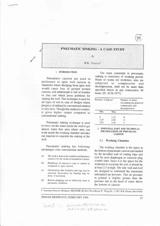
2.3. Air Lock
An air lock is required for each shaft.
It is mognted on top of the shafts and
extends above water level. The function of
air lock is to permit the workmen and
materials to go in and out of the caisson
without releasing pressure in the caisson.
Air-Iock consists of steel chamber with
two air-tight doors one of which opens to
shaft and other opens to atmosphere. When
a man enters the air lock through the
outside door, the pressule in the air lock
is equal to that of atmosphere and then the
door is closed and air pressrue is allowed
'1q.
to rise slowly. When the pressure in the air
lock becomes equal to that of inside of
caisson, the door to the shaft is opened and
men may descend into the working chamber.
The procedure is reversed when a rfian
comes out of carsson. However,
decompression is done slowly due to
obvious reasons as shown in Fig. 1.
3. SAFETY PRECAUTIONS
3.1. For safety and welfare of workmen,
the following precautions should be
exercised:
(a) Accurate Control of Air Pressure:
A gauge attendant should watch the
pressure gauge constantlY. Gauge
should be accurate and in good
working condition.
(b) Sufficient Air Circulation : To avoid
the air in the working chamber
becoming stale, fresh air must be
circulated into working chamber
constantly. This may be done bY
opening a valve in the air lock. In
granular soil where certain amount
of leakage takes place through cutting
edge and the soil, the air is
automaticallY circulated.
(c) Slow DecomPression : If men are
coming out too fast, they may develop
caisson disease. This disease is due
to air bubbtes formed in the blood
,pnd tissues which are compressed
dr-rring working under Pressure'
(d) Duplicate and SPare EquiPment :
A stand-by set of air compressor and
other equiPment for Pneumatic
28 INDIAN HIGHWAYS, FEBRUARY 1996
3. 1
I ""/
LF'
AIR LOC K
SHAFT
GIJY ING ROPE
STEINING
LA DDER
=------:_-_-j
- -__: _SIE_E! D TAPHRAGM
DR EDGED MAT ER
:+EE+%RARY PLATFORU
WORKING CHAMBER
WE LL CUR B
CUTTING EDGE
MUCK BUC KET ( .25 VI
3 I
Fig. 1. Air lock and shaft arrangement (Pneumatic Sinking)
(e)
operation should be provided for use
in the case of emergency.
Illumination Inside Working
Chamber : Proper illumtnation should
be maintained inside the working
chamber. This will add to more output.
Normally, white paint is done inside
shaft and air lock to improve
itlumination.
Signalling Arrangement : There is
no direct communication between
person working under pneumatic air
and outside attendant. A site signalhng
arrangement is adjusted between the
lock attendment and person working
inside the air lock. This will be
specially helpful in taking out matenal
from chamber (i.e. rnuck).
Control of Work : Work inside
working chamber should be under
supervision of responsible Engineer/
Supervisor. Blasting should be done
very carefully.
Caution about Incidental Loading:
Sometirnes outcoming bucket through
,, the shaft gets obstnrcted in the ladder
and the winch rope collapses resulting
in sudden fall of bucket into working
chamber, Whenever there is a
bucketing opqration, no person should
(e)
(h)
(f)
INDIAN HIG}IWAYS, FEBRUARY 1996 29
4. be allowed to stand in the central
ponion of the working chamber, Apart
from these, there are chances of
falling of big boulders (being raken
oul) from the bucket.
3.2, General Instructioru
(a) workers under compressed air shoutd
be older rhan 20 yeus but below 40
years.
(b) A11 employees should be medically
examined carefully before they are
selected for working under
compressed air. They should also be
periodically examined after 15 days.
(c) One should not go in shaft with
empty stomach.
(d) Alcoholic drinks should be avoided.
(e) Limbs should be moved freely during
de c ompre s sio4 to s ti mul a te
circulation.
(f) One must not work more than one
shaft.
(g) Unauthorised manipulation of valves
on the compressed air pipe is very
dangerous for the health of all
ernployees. OnIy the lock attendant
is allowed to handle ttlem.
(h) Personnel should not be allowed to
carry any match box in the air lock
and nobody be allowed to smoke.
4. LIMITATIONS OF PNEUMATIC
TECHMQTIE
Following are the limitations in
pneumatic techniques:
(a) The depth of penetration below the
water level is limired to 35 m
needing compression of 3.5 Kg/cmz"
The pressure higher than this is beyond
the endurance of human body.
(b) Due to limited working hor:rs possible
. in the method the progress of work
is not very fast. With the increase in
the pressure, the working hours will
reduce.
(c) Working in pneumatic condition,
sometimes creates problems in body
known as caisson sickness. Symptoms
are as below:
(i) Local pain in arms or legs
(called bends)
(ii) Incoherence of speech
(iii) Severe pain in chest or abdomen
(iv) Paralysis generaily in legs
(v) Sometimes unconscrousness
(vi) Head-ache.
5. E}GCUTION OF WELL FOI.INDATION
OF 704 M LONG BRIDGE
5.1. Case Study
A case study of well forurdation
execution of a major permanent bridge
over a perennial river in North-Eastern
region has been discussed. Foundation
depth of the bridge is more and overall
perspective of well sinking is a difficult
task. The sub-soil consists of large boulders
of 2 to 3 rnetres in diameter in upper depth
of about 25 metres and after that soil is of
silt-sand-aggregate matrix, In the initial
stage open grabbing with crane-grab was
carried out for about 12 metres depth and
after that the rate of sinking was 10 to
30 INDIAN HIGHWAYS, FEBRUARY I 996
5. 20 mrn per day. To expedite the progress,
the pneumatic arrangement was set at site
and progress was increased to 150 mm to
200 nun per day as shown in Fig. 2,
5.2. Hydraulic Data and Important
Features of Bridge
The description of the bridge is as
follows:
(a) Length of 704 m between in side
bridge face of the abutment
dirt walls.
(b) Type of Prestressed concrete
bridge single cell box girder
of balanced cantilever
construction.
(c) Deck level
(d) Maximum
surface
velocity of
water at HFL
(e) Maximum
vertical
clearance
(f) Clear carriageway
width between
inside faces of
road kerbs
(g) Footpaths
RL 179.80 m
j .8 m/Sec
8m
7.5 m
L.5 m wide on both
s ide s of the
carriageway
MEBO gtDE
Fig. 2. General arrangement
INDIAN,HIGFTWAYS, FEBRUARY 1996 31
6. g
TECHNICAL.PAPERS
(h) Foundation
(i) Typr - Circular well
(ii) Outer - 11.70 m
diameter
(iii) Inside - 6.64 m
diameter
(iv) Steining - 2.53 n
thickne ss
(v) Well curb - 4.5 m
height
(vi) cutting
:r?'yJiffi:
(vii)
*l.l#edge
- 33 degree
(viii)
3Jl3|,."Jt",.
- Mzs
steining
6. SET-L,P OF EQIIPMENT AND PLANT
6.1, The layout ensured minimum
movement of materials, equipment and
personnel as well as proper drainage of the
area. Wind conditions taken into
consideration in operation of some
equipment for example, when lower crane
operation is not possible in heavy winds.
Suppofting facilities such as generators,
office stores etc. was not to be located in
the path of dust-blow. Adequate space be
provided for handling and storage of raw
materials as well for finished products.
Wherever, practicable separate seivice
road should be proviced for in-coming
material and out-going products and the
service road maintained properly.
6.2.Equipment Required for
Compressed Air Plant
Following equipment are required
for compressed air plant:
Description Capacity Numbers",
(a)
(b)
(c)
(d)
(e)
(0
(g)
(h)
AC Generator
Air Compressor
Air Lock
Medical Lock
Air Receiver
Air Filter
Moisture Separator
Carbon Filter
110 KVA
513 CFM
3m3
Miscellaneous Requirements
(a) Ughting accessories.
(b) Pipes of various sizes with accessories.
(c) Water pump for comprossor needing cooling.
(d) Water pump for air lock cooling.
(e) Electric switch gear with various gauges.
(0 Hand lamp with 24 voht bulbs.
In addition to above mentioned
equipment, there vre other minor
requirements for completing the layout of
equipment and plant shown in Plate 1.
6.3. Requirement for Diaphragrn
and Inside Working Chamber
(a) Steel diaphragm with accessories for
f i tting arrang e ment/c oncre te
diaphragm/corbel slab.
(b) 1.057 metres (42 inches) dia adopter
pipe (shaft) of 2 to 2.5 m height.
(c) Winch motor in air lock 7.5 HP.
(d) Muck buckets 0.25 m3
(e) Bracket assemblies for winch (to be
attached in air lock).
(f) Hand winches for movable platforrn.
(g)
,,
Jack hammers
(h) Flight pump
0) Pavement brakers
(k) Turn brackets for guys
2
2
I
1
3
32 INDIAN HIGFTWAYS, IiEBRUARY 1996
7. ! ./'
v,
(l) I adder below platform inside the
chamber to working area
(m) Mining torch
(n) Mathanometer
(o) Fire extinguisher
(p) Rubber hand gloves
(q) Hammers of various sizes
(r) Shovels
(s) Crowbars
(t) Pick axes
(u) Drilt rod
(v) Safety valve
(w) Miscellaneous equipment, telephone,
bucket, fixed and rnovable platforfi].
(x) Miscellaneous stores.
6.4.Pneumatic Sinking at Fier Well
No. P6
(a) Before starting the work at this
location bore log detail of the location
were examined and accordinglY the
strategy for surkmg well foundation
was formed. From the bore log details
it was obvious that sinking a well in
. soil underneath with open grabbin.-e
may not be possible due to packed
bouldery strata as shown, Design of
the well foundation catered for the
pneumatic condition also.
(b) WeEl foundation construction at this
location was started in January 1989
rvith the placing cf cutting edge ai
Bore Log Data
L62 " 140
158 " 000
156.56
15 5 .20
Ni3 Core recovery
Bouldery and cobbles
of white and brownish
quarticite
NiI core recovery
Boulders and cobbJes
of greyish whit,e
gritty guartzite
j-47 . 04 Boulders and cobbles
of greyish white
quartz ite
Boulders and cobbles
greyish white and
quardz i te
Boulders of greyish
white gritty and
brownish quartzite
r42. 3 7
136 .7 4
INDIAN HIGHWAYS, FEBRUARY T996 33
8. F
,J
}..
ground RL of 160"735. Conventional
sinking was adopted with the use of
Tata crane having grab of 1.2 cum
cap acity and diver were also
de ploye d af ter reac hing at
considerable depth to expedite the
rate of sinking. This work was
continued till June 1990 and average
rate of sinking observed during the
period was approximately 7 cm per
day. But the rate of sinlcing during
las t month bef ore suspending
conventional sinJcing was 1 cm. It
was felt that further rute of sinking
in subsequent depth may be very
less. Wittr the pneumatic sinking
technique the rate of sinking got
expedited and average rate of
sinking achieved was 4 cm upto
foundation RL at 125.00.
(c) Fneurnatic sinking was atternpted at
well No P6 w.e.f. 4th July 90 at RL
145.360 Mus. Steel diaphragm was
placed at gauge height of 14 m. This
technique was continued upto design
founding level of I25 m. During
the course of sinking, boulders upto
2 m size were encountered which
led to slowing down the sinking
technique as boulders more than 50
cm size cannot be taken out because
of limitation of muck bucket. There
is a variation in water level of river
frorn 153.500 metres to 163.000
metres furing the year. It was obvious
that deeper we dug, more was the
pressure and progress got slowed
down. This led to increase in
compre ssion and decompression time.
However, limited progress was
assured in this technique. Out of
total sinking of 35.805 metres,
15.350 metres was conventional and
remaining 20.300 metres was by
pneumatic sinking.
(d) Output of sinking depends upon
various factors which include size
of bucket, depth of well, type of
strata, water head, size of shaft and
arlock. Team of group deployed
inside the working charnber comprised
of one Engineer two Supervisors and
twenty skilled labor:rers. One metre
of sinking required 1 10 m3 of
material which in turn require MA
buckets to take out dredged material
as the capacity of one bucket was
0.25 m3. The progress of work
changed with the depth of sinking,
deeper we dug lesser was the
p'rogress. However, certain percentage
of reli able progres s could be
'achieved
within specified time. Rate
of sinking reduced with progressive
sinking as at increased pressure,
sinking gets reduced.
6.5. Soil Strata Encountered is was
follows
S. No. Total Sinking
Achieved (M)
Average
rate of
sinking
per day
1. Conventional Sinking 7 cm
= 15,350 m
2. Pneumatic Sinking 4. cm
= 20.455 m
Total Sinking = 35.805 m
(d) All the precautions were followed to
34 INDIAN HIGI{WAYS, FEBRUARY 1996
9. l-'
Pictorial DescriPtion
Ca'p'v€runot-)At- SttJK I lU(1
RL
160.735
150.780
145.360
r4r. 180
130, 730
avoid any caisson sickness but still
few workmen had this Problem when
RL was below 130 m. Pneumatic
sinking is costly comPared to
conventional sinking but certain
amount of targetted progress can be
thought of even if strata is tougher
one.
Strata descriPtion
Strata comprising of
sand silt mixed with
-u-93__?::Iders
s ize
varying from 300 to
600 mm
*?t*" 6;;'1"[i5:3"
size varying from
600 mm to 900mm.
60t red c lay mix
Sandy soil mixed
with boulders
varying from 300 mm
to 1-500 mm.
Compacted strata
comprising of red
cJ"ayey sandy so i I
40*. Boulders uPto
300 mm 30%.
Boulders 300 to 700
mm = 30%.
flhl Pruap',ATtc s FtuKtM(
7, CONCLUSIONS
Pneumatic sinking technique is applied
to expedite the progress of sinking but
this technique has also limitations and
applicable upto a pressure of 3.5 Kg/cm2.
Site engineer needs to be thoroughly updated
about the plants and processes to avoid
any catastrophe during execution of work.
r25. 000
C ti
Soil strata encountered
INDIAN HIGIIWAYS, FEBRIJARY 1996 35