Study on Air-Water & Water-Water Heat Exchange in a Finned Tube Exchanger
SPE171748 Surface Safety System for ZADCO (4).pdf
1. SPE 171748
Surface Safety System Enhances Gas Lift Safety and Optimizes Surface
Line Architecture on Island Wells
Daniel Newton, William Odom, Graham Burchell, Curtis Kofoed, Zakum Development Company, Kristian Harestad,
PTC
Copyright 2014, Society of Petroleum Engineers
This paper was prepared for presentation at the Abu Dhabi International Petroleum Exhibition and Conference held in Abu Dhabi, UAE, 10–13 November 2014.
This paper was selected for presentation by an SPE program committee following review of information contained in an abstract submitted by the author(s). Contents of the paper have not been
reviewed by the Society of Petroleum Engineers and are subject to correction by the author(s). The material does not necessarily reflect any position of the Society of Petroleum Engineers, its
officers, or members. Electronic reproduction, distribution, or storage of any part of this paper without the written consent of the Society of Petroleum Engineers is prohibited. Permission to
reproduce in print is restricted to an abstract of not more than 300 words; illustrations may not be copied. The abstract must contain conspicuous acknowledgment of SPE copyright.
Abstract
The construction of drilling and production facilities for gas lift production and injection wells on artificial Islands provides
a significant exposure to risk due to SIMOPS. Specifically, simultaneous drilling operations results in rig skidding operations
over/near to live well cellars and production line trenches. This increases the risk of venting significant lift gas volumes to
atmosphere in a manned area through dropped objects or other failures.
The authors describe a Lift Gas Safety System (LGSS) to be implemented that will prevent venting lift gas during both a
dropped object and other unplanned incidents leading to loss of integrity (e.g. ESD). The system also provides benefits
through improved annular pressure monitoring (APM) and confining barriers within the wellhead. Outlined is the
implementation process by which the system was selected and which subsequently led to optimization of surface facilities
from the well cellars through to the production manifold.
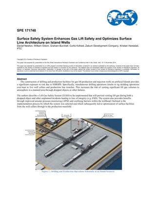
Figure 1 : Drilling and Production Operations Schematic in an Island Scenario
2. 2 SPE 171748
Introduction
Island developments present an environment whereby production wells are drilled using extended reach techniques out to
targets with long offsets from the Island position. The Island wells are also located in close proximity (400 metres or less) to
processing facilities, drilling operations, well intervention activities, well services and the associated infrastructure and
personnel including base camps. Most new wells are able to naturally sustain flow of hydrocarbons to the surface, however,
for those wells that are unable to naturally flow (due to low reservoir pressure support and high water cut) gas lift can be used
to artificially lift and improve production rates. For naturally flowing wells, gas lift is utilized to achieve certain target
production uplift to meet predefined reservoir/area target rates, and extend plateau.
The well annulus differs from a typical topside process plant in that its inventory of gas is not normally vented or blown
down to flare in an emergency, instead the Wing Valve is closed and the gas contained within the annulus itself.
The ERD nature (sail angles of up to 82 degrees) of the Island wells places the measured depth within the upper
completion to the deepest gas lift mandrel up to 14,000ft. The annular volume of pressurized lift gas in these wells exceeds
4,000 cubic feet per well. This volume of injection gas is planned to be injected at 1,500psi per well. A standard 1.4m height
high pressure industrial gas cyclinder will hold ~1.7ft3
of gas. Per production well this leads to an equivalent of ~2300 gas
cylinders being present in the “A” Annulus in each production well. At current projected field development well counts this
would result in each of the four artificial Islands having, on average, between 150,000ft3 and 230,000ft3 of pressurized
injection gas within the annular volume per Island, at any given time (~130,000 gas cylinders).
Figure 2 : Representation of the volume of gas present in a single production well annulus
The location of processing, drilling operations, well intervention facilities and base camps on the Islands results in more
than 400 people living and working on each of the Islands. Drilling activities will often be occurring within 6 metres of live
wells (well centre to well centre distance). These activities include skidding operations whereby drilling rigs will move over
the top of pressurised wells to move from well slot to well slot.
The Island wells initially planned to utilize industry standard surface gas lift setup with a non-return check valve (NRV) on
the injection line at some distance from the wellhead. However, failure of the “A” annulus valves or surface lines between this
NRV and the wellhead will result in an uncontrolled release of pressurised lift gas inventory from the “A” annulus to
atmosphere. Such a large volume of pressurized gas poses significant risk to the Island’s personnel and facilities if it is not
contained in the event of an emergency. Simultaneous production and well operations lead to a higher risk of such an event
occurring. Initially this would rank the risk level for these gas lift operations on artificial Islands at high, with simultaneous
drilling and production. As per Figure 2 a risk ranking of C5 would be assigned due to the history of similar incidents
occurring globally in the Oil & Gas sector (e.g. Piper Alpha, ONGC Mumbai High North and PTTEP Montara) being well
documented and the severity of such an incident on an island may be catastrophic, including the possibility for fatalities. This
highlights a gap between the current base well design and the requirements to minimize risks and mitigate hazards for
SIMOPS on the Islands.
3. SPE 171748 3
Figure 3 : HSE Risk Matrix
A review was performed of the base well design and surface line architecture based on the initial identification of a high
risk level operation. The review team was tasked to identify a solution that would lower the risk level through:
• Actively containing the gas within the well on triggering of an associated well Emergency Shut Down (ESD)
system.
• Providing a facility to monitor annular pressures with instrumentation while the annulus is shut in.
• Maintaining well integrity with a two barrier philosophy that meets company well integrity standards.
Base Well Design
The Island well completion design was originally planned to be a standard single completion with the following components:
• Downhole Safety Valve (DHSV)
• Master Gate Valves (LMGV & UMGV)
• Wing Valves (LIWV, LOWV, RIWV & ROWV)
• Gas Lift Mandrels & Valves (GLM & GLV)
• Cased Hole Packer
Figure 4 : Base Completion and Wellhead Design
R
O
W
V
L
O
W
V
4. 4 SPE 171748
Figure 5 : Base Surface Line Design
Surface line architecture for the “A” annulus included separate bleed and injection lines on each annular outlet. These lines
in turn were installed into a trench from the wellhead back to the main production line rack. Annulus pressure monitoring was
planned to be via the bleed line at rack location.
The review identified key aspects of the base design that were considered deficient in minimizing the risk of venting lift
gas and also identified aspects of the well design which did not meet the required two barrier philosophy, namely:
• During ESD, gas lift and gas injection check valve closure is reliant on depressurisation of the line upstream of
the check valve. The check valve includes a bypass line (for equalization purposes) that includes a manual gate
valve. The next failsafe valve upstream of the check valve was located at the pipe rack.
• During both gas-lift and non-gas lift production (and associated ESD’s), a 2” bleed line remains pressured within
the trench area extending away from the wellhead to the normally closed gate valve in the rack area 42 ft. away.
• Bleed off of injection gas following ESD required manual bypass of the check valve at the cellar or the NC gate
valve on the bleed line in the pipe rack - both operations requiring human intervention at the well site.
• Only limited dropped object protection would be provided by an Elevated Work Platform (EWP) above the bleed
line close to the wellhead. The EWP only covers a portion of the bleed line in the cellar area. The injection line
was not planned to be covered
• If the annulus was shut in at both manual outlet gate valves there was no means to monitor the pressure in the “A”
Annulus.
• Two barrier philosophy was reliant on valves outside of wellbore / wellhead. To maintain a two barrier
philosophy within the well, the gas lift valves (or dummy valves) must perform as a barrier and the “A” annulus
gate valves on each outlet must be closed. Closure of the annular gate valves prevents lift gas injection and does
not allow for fluid bleed off during thermal expansion of annular fluids.
5. SPE 171748 5
Figure 6 : Base Surface Line Design showing barrier envelopes
The review identified the need to incorporate additional barriers into the well design to safe guard against the release of
annular lift gas. A review of available gas lift safety system solutions was performed.
Traditional Lift Gas Safety Systems
Traditional gas lift safety systems are either on surface, outside the wellhead area, within the production piping (Type A) or
downhole, deployed as part of the well completion (Type B). Currently available systems for both type A and type B were
reviewed for their applicability to Island production and drilling operations with the focus on:
• Maintaining two barrier policy for well integrity (given the wells can sustain natural flow to surface)
• Minimizing the volume of lift gas that has the potential to be vented
• Minimizing additional complexity and maintaining reliability of the well design
6. 6 SPE 171748
Figure 7 : LGSS Summary Table
The review of available Lift Gas Safety Systems resulted in the selection of a combination of downhole barrier gas lift
valves in addition to hydraulically actuated annular safety valves installed within the VR profile of the casing spool. This
system provided the greatest risk mitigation, met barrier policy requirements while also minimizing future workover costs and
without introducing additional downhole completion complexity.
Figure 8 : Damaged annulus outlet showing with and without VR safety valve
7. SPE 171748 7
Lift Gas Safety System
The LGSS consists of the following:
• A dart type (fail safe closed) check valve. The check valve is installed (threaded) into the annulus line valve
replacement (VR) profile.
• A flow tube hydraulic actuator used to hydraulically open the check valve. It also facilitates pressure bleed off
from the “A” annulus for integrity testing of the gas lift valves installed in the completion string. The hydraulic
actuator is normally connected to the ESD system such that the valve is open whenever the actuated Xmas tree
valves are open and closed when they are closed.
• The actuator and valve are separate items such that if the actuator and spool piece were to be separated from the
wellhead during an incident, the valve will remain within the VR profile in the wellhead and act as a barrier.
• A spool piece, installed between the annulus outlet and the first gate valve. The spool piece has a penetration to
allow hydraulic fluid from the ESD panel to supply pressure to the hydraulic actuator as well as appropriate seal
bores to seal the hydraulic actuator within the spool.
Figure 9 : LGSS Assembly
Tests/reviews performed on the Lift Gas Safety System during the evaluation period:
• Validation test of the actuated valve according to API 6A F.1.15
• Validation testing of the hydraulic actuator according to API 6A F.1.15.1
• Fire Test of water pressurized valve according to API 6FB (part I) and 6FD
• Fire Test of gas pressurized valve according to API 6FB (part I) and 6FD
• Flow test of valve, 4bpm @ 500 bbl. with and without spring return in valve
• CFD analysis of valve to model the flow test at 4bpm
• FMECA report for the valve and actuator
• Evaluation of the valve and actuator system regarding ignition hazard according to ATEX 94/9/EC zone 0
• Independent Review Certificate for the selected LGSS according to API 6A: 20th Edition: 2010 NACE MR0175
ISO15156:2009
“A” & “B” Annulus Monitoring Instrumentation
The monitoring system consists of the following:
• Annulus Pressure and Temperature Sensor installed within a VR plug providing a primary barrier
• Sensor ceramic bulkhead tested to gas tight criteria which provides a secondary barrier
• System is available in either wired or wireless HART data transmission protocols (Pressure and Temperature)
• System is available with wired power or battery power.
• System is designed such that if the electronic section is removed during an incident the plug section will remain in
the VR profile acting as a barrier.
8. 8 SPE 171748
Figure 10 : Annulus Monitoring System (AMS)
Tests/reviews performed on the Annulus Monitoring System (AMS) during the evaluation period:
• Fire Test of AMS according to API 6FB (part 1, sect 3.2.1) and 6FD
• EC-Type Examination Certificate. (ATEX certification) according to ATEX 94/9/EC zone 0 for wired version of
sensor
• Independent Review Certificate for AMS according to API 6A: 20th Edition: 2010 NACE MR0175
ISO15156:2009
• HART conformance test according to HART Communication Protocol Requirements
• Hart Communication verified according to HCF method
• Long Term test of the AMS over 18 months, 2 Sensors running continuous cycles (1 cycle per week) of pressure
built up (100Barg) and bleed off, measured against a calibrated pressure transmitter.
• Shock & Vibration testing. HALT - according to IEC 62506. Shock and Vibration - according to IEC 60068
Well design optimized for lift gas safety
The selected system provided the ability to:
• Actively containing the gas within the well on triggering of Emergency Shut Down (ESD) System.
• Monitor annular pressures with instrumentation while the annulus is shut in.
• Maintain well integrity with a two barrier philosophy that met company well integrity standards.
Figure 11 : Well Design optimized with LGSS and Annulus Monitoring
R
O
W
V
L
O
W
V
9. SPE 171748 9
Figure 12 : Optimized well design with barrier envelope
Figure 13 : Wellhead showing LGSS on “A” Annulus and VR
Sensors installed on “A” + “B” Annulus
Figure 14 : Wellhead with LGSS flange removed through
incident and VR Safety Valve remaining as barrier
Figure 15 : Wellhead with VR Sensor flange removed through incident and VR Sensor Plug remaining as barrier
Optimized Surface Facilities
The outcomes from the risk review led to significant reduction in high alloy piping, valves and instrumentation between the
wellheads and the manifold pipe racks. Figure 16 is a simplified before and after illustration of the facilities on a typical
production wellhead. The orange facilities highlighted on the left of Figure 16 depict some of the piping and valves that were
10. 10 SPE 171748
able to be deleted from the design. Additionally significant downstream piping, valves and instrumentation on the manifold
pipe rack (not shown in Figure 16) were able to be deleted from the design.
Figure 16 : Production wellhead surface piping comparison
In addition to the safety benefits of less facilities subjected to damage from drilling and maintenance operations, there is a
direct cost savings achieved through the optimization of surface facilities. These savings are derived from the deletion of
facilities (estimated quantities of piping, valves and instruments) and the associated costs to fabricate, install, and test those
facilities. The large number of wells planned for full field development, coupled with the high cost of alloy materials (Inconel
625), combines to provide significant cost savings. The costs savings far exceeded the cost of implementing the new LGSS
technology into the field development.
Other benefits
Analysis of SIMOPS in relation to barriers and well control while skidding drilling rigs over a live well identified the
potential for other benefits of the system. The LGSS and AMS combination would permit skidding a rig with pressurized
annular gas or live gas injection rather than the original plan of bleeding down annulus lift gas and shutting in production.
Project Execution
Equipment has been procured with first installations planned for Q4 2014 following successful system integration testing.
The system design provides the flexibility for the equipment to be installed during wellhead manufacture, in a workshop to the
casing spool’s annular outlets or in-situ to already installed casing spools. The first installations performed will be in-situ to
casing spools currently installed on production wells.
The systems procured also have the added flexibility to adjust to differing data transmission and power supply types when
moving the artificial Island project from the initial production (temporary) phase to full field (permanent) production phase.
Initial production will be set up for wireless data transmission with power supplied by integral batteries whilst full field
production will be setup for wired data transmission and power supply.
Conclusion and Results
The revised well design which includes the use of a surface deployed Lift Gas Safety System (LGSS) in conjunction with
annulus monitoring systems (AMS) has addressed several well integrity issues surrounding the use of high pressure lift gas
within ERD production wells on artificial Islands with simultaneous production and drilling operations.
11. SPE 171748 11
The revised well design provides a solution that lowers the risk level associated with SIMOPS and gas lift operations
through:
• Actively containing the gas within the well on triggering of Emergency Shut Down (ESD) System.
• Providing a facility to monitor annular pressures with instrumentation while the annulus is shut in.
• Maintaining well integrity with a two barrier philosophy that meets company well integrity standards.
This revised well design allowed for significant flow on improvements to surface line architecture resulting in significant
cost savings to the project.
Acknowledgements
The authors would like to express their gratitude to the managements of ZADCO and PTC for their permission to publish
this paper. We would also like to thank Campbell Mitchell and Osama Khedr for their contribution and ZADCO management
for their stewardship of the project.
Abbreviations Used
AMS: Annulus Monitoring System
DHSV: Downhole Safety Valve
ERD: Extended Reach Drilling
ESD: Emergency Shutdown
EWP: Elevated Work Platform
GLM: Gas Lift Mandrel
GLV: Gas Lift Valve
LGSS: Lift Gas Safety System
LIWV, LOWV, RIWV & ROWV: Left/Right Inner/Outer Wing Valves
LMGV & UMGV: Lower & Upper Master Gate Valves
VR: Valve Replacement
References
• ISO 10423:2009 (API6A), Petroleum and Natural Gas Industries – Drilling and production equipment –Wellhead
and Christmas tree equipment.
• IEC 62506:2013, Methods for product accelerated testing
• IEC 60068:2013, Environmental testing - Part 1: General and guidance
• NACE MR0175 ISO15156:2009, Petroleum and Natural Gas Industries – Materials for Use in H2S Containing
• Environments in Oil and Gas Production
• API 6FB, Fire Test for End Connections
• API 6FD, Specification for Fire Test for Check Valves
• ATEX Directive 94/9/EC Guidelines – 4th Edition, September 2012
• ISO 17078-2:2007, Flow control devices for side-pocket mandrels
• Norsok D-10, Rev. 4, June 2014, Well integrity in drilling and well operations
• OTC 20820 Taking the gas lift valves to a new level of reliability
• Brodie, Alan. PTC. Enhanced Gas Lifted Well Integrity Whitepaper