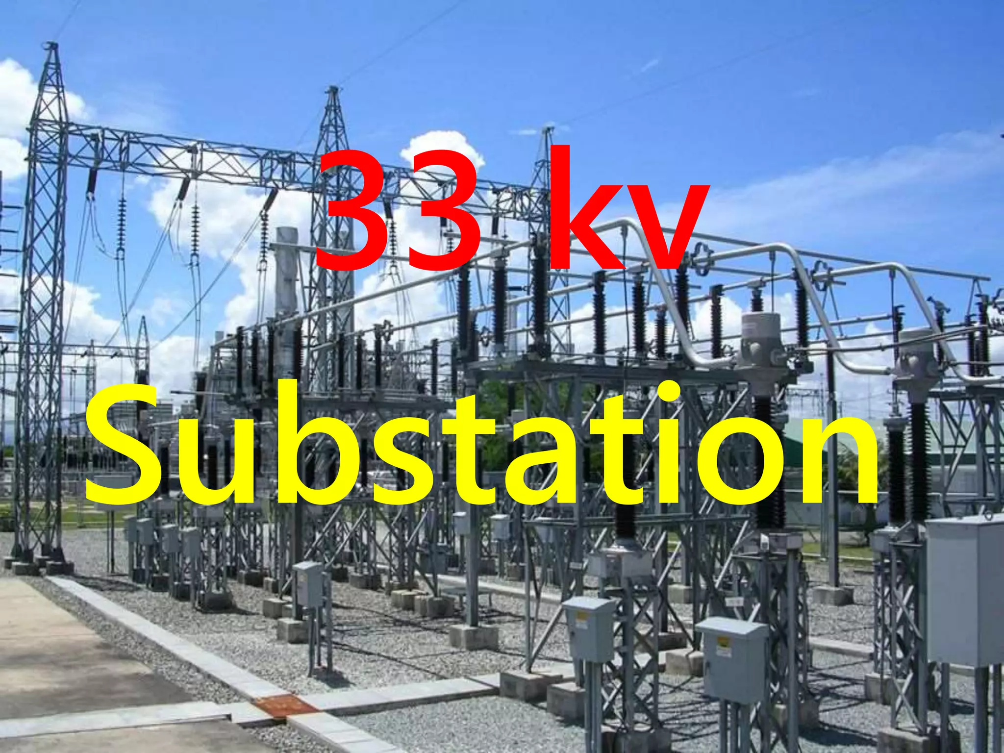
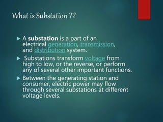
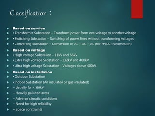
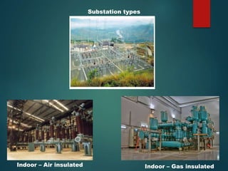
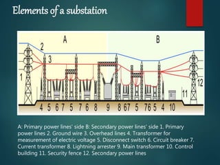
33 kv
Substation
What is Substation ??
 A substation is a part of an
electrical generation, transmission,
and distribution system.
 Substations transform voltage from
high to low, or the reverse, or perform
any of several other important functions.
 Between the generating station and
consumer, electric power may flow
through several substations at different
voltage levels.
Classification :
 Based on service
 • Transformer Substation – Transform power from one voltage to another voltage
 • Switching Substation – Switching of power lines without transforming voltages
 • Converting Substation – Conversion of AC - DC – AC (for HVDC transmission)
 Based on voltage
 • High voltage Substation - 11kV and 66kV
 • Extra high voltage Substation - 132kV and 400kV
 • Ultra high voltage Substation – Voltages above 400kV
 Based on installation
 • Outdoor Substation
 • Indoor Substation (Air insulated or gas insulated)
 − Usually for < 66kV
 − Heavily polluted areas
 − Adverse climatic conditions
 − Need for high reliability
 − Space constraints
Substation types
Indoor – Air insulated Indoor – Gas insulated
Function of a substation
 The purpose of a substation is to 'step down' high
voltage electricity from the transmission system to
lower voltage electricity so it can be easily supplied to
homes and businesses through our distribution lines.
 Supply electric power to consumers continuously
 • Supply of electric power within specified voltage
limits
 • Shortest possible fault duration
 • Optimum efficiency of electrical network
 • Supply of electrical energy to consumers at lowest
cost
Design &
Working of 33 kv
substation
Elements of a substation
A: Primary power lines' side B: Secondary power lines' side 1. Primary
power lines 2. Ground wire 3. Overhead lines 4. Transformer for
measurement of electric voltage 5. Disconnect switch 6. Circuit breaker 7.
Current transformer 8. Lightning arrester 9. Main transformer 10. Control
building 11. Security fence 12. Secondary power lines
BUSBAR
• BUSBAR (or bus, for short)- An electrical bus bar is defined as a
conductor or a group of conductor used for collecting electric power
from the incoming feeders and distributes them to the outgoing
feeders.
Busbars
(long heavy
tube type
DISCONNECTS/Isolator -
Open an electrical circuit, isolating the downstream circuit for purposes of
inspection and maintenance. Low-voltagedisconnect switches are often
used as main disconnecting devices in switchboards.
Disconnect Switch
( moving contact rod (A) &
contacts with flexible
fingers (B)
(A)
(B)
CIRCUIT BREAKER
A circuit breaker is an automatically operated electrical switch designed to
protect an electrical circuit from damage caused by excess current, typically
resulting from an overload or short circuit.
Circuit Breakers
( Connected in a
3-
phase circuit
Operating
Mechanism
Panel
CURRENT TRANSFORMER
• CURRENT TRANSFORMER – Current transformers (CT) are a series connected
type of instrument transformer. They are designed to present negligible load to
the supply being measured and have an accurate current ratio and phase
relationship to enable accurate secondary connected metering.
VOLTAGE TRANSFORMER
Voltage transformers (VT), also called potential transformers (PT), are a parallel
connected type of instrument transformer. They are designed to present
negligible load to the supply being measured and have an accurate voltage
ratio and phase relationship to enable accurate secondary connected
metering.
EARTHING SWITCH
• EARTHING SWITCH – also known as ground disconnect, which
used to connects the equipment to a grid of electrical
conductors buried in the earth on the station property. It is
intended to protect people working on the grounded
equipment. It does this by completing a circuit path, thereby
reducing the voltage difference between the equipment and
its surroundings.
Lightning Arresters
A lightning arrester is a device used to
protect the insulation and conductors of the
system from the damaging effects of lightning.
The typical lightning arrester has a high-
voltage terminal and a ground terminal. When
a lightning surge (or switching surge, which is
very similar) travels along the power line to the
arrester, the current from the surge is diverted
through the arrestor, in most cases to earth.
3D Animation of 33/11kv Substation
References
3
https://www.siemens.com/global/en/home/products/
energy/high-voltage/hv-switchgear/disconnectors-
earthing-switches.html
4 .http://circuitglobe.com/electrical-bus-bar-and-its-
types.html
1 .Wikipedia
2 . Video from odesssey pvt. Ltd.
Conclusion
By this project, we know electricity plays a major role
in our daily life ,we know how we get desired
electricity from power plant.
We also learn how a substation works in electricity
transmission and distribution and working of the
different element of substation .
We have to save electricity to save our resources.
Thank
YOU
Made by- Abhishek Dawachya (16EE01040)
Guided By- Dr. Sankarsan Mohapatro sir

33kv substation

  • 1.
  • 2.
    What is Substation??  A substation is a part of an electrical generation, transmission, and distribution system.  Substations transform voltage from high to low, or the reverse, or perform any of several other important functions.  Between the generating station and consumer, electric power may flow through several substations at different voltage levels.
  • 3.
    Classification :  Basedon service  • Transformer Substation – Transform power from one voltage to another voltage  • Switching Substation – Switching of power lines without transforming voltages  • Converting Substation – Conversion of AC - DC – AC (for HVDC transmission)  Based on voltage  • High voltage Substation - 11kV and 66kV  • Extra high voltage Substation - 132kV and 400kV  • Ultra high voltage Substation – Voltages above 400kV  Based on installation  • Outdoor Substation  • Indoor Substation (Air insulated or gas insulated)  − Usually for < 66kV  − Heavily polluted areas  − Adverse climatic conditions  − Need for high reliability  − Space constraints
  • 4.
    Substation types Indoor –Air insulated Indoor – Gas insulated
  • 5.
    Function of asubstation  The purpose of a substation is to 'step down' high voltage electricity from the transmission system to lower voltage electricity so it can be easily supplied to homes and businesses through our distribution lines.  Supply electric power to consumers continuously  • Supply of electric power within specified voltage limits  • Shortest possible fault duration  • Optimum efficiency of electrical network  • Supply of electrical energy to consumers at lowest cost
  • 7.
    Design & Working of33 kv substation
  • 8.
    Elements of asubstation A: Primary power lines' side B: Secondary power lines' side 1. Primary power lines 2. Ground wire 3. Overhead lines 4. Transformer for measurement of electric voltage 5. Disconnect switch 6. Circuit breaker 7. Current transformer 8. Lightning arrester 9. Main transformer 10. Control building 11. Security fence 12. Secondary power lines
  • 9.
    BUSBAR • BUSBAR (orbus, for short)- An electrical bus bar is defined as a conductor or a group of conductor used for collecting electric power from the incoming feeders and distributes them to the outgoing feeders. Busbars (long heavy tube type
  • 10.
    DISCONNECTS/Isolator - Open anelectrical circuit, isolating the downstream circuit for purposes of inspection and maintenance. Low-voltagedisconnect switches are often used as main disconnecting devices in switchboards. Disconnect Switch ( moving contact rod (A) & contacts with flexible fingers (B) (A) (B)
  • 11.
    CIRCUIT BREAKER A circuitbreaker is an automatically operated electrical switch designed to protect an electrical circuit from damage caused by excess current, typically resulting from an overload or short circuit. Circuit Breakers ( Connected in a 3- phase circuit Operating Mechanism Panel
  • 12.
    CURRENT TRANSFORMER • CURRENTTRANSFORMER – Current transformers (CT) are a series connected type of instrument transformer. They are designed to present negligible load to the supply being measured and have an accurate current ratio and phase relationship to enable accurate secondary connected metering.
  • 13.
    VOLTAGE TRANSFORMER Voltage transformers(VT), also called potential transformers (PT), are a parallel connected type of instrument transformer. They are designed to present negligible load to the supply being measured and have an accurate voltage ratio and phase relationship to enable accurate secondary connected metering.
  • 14.
    EARTHING SWITCH • EARTHINGSWITCH – also known as ground disconnect, which used to connects the equipment to a grid of electrical conductors buried in the earth on the station property. It is intended to protect people working on the grounded equipment. It does this by completing a circuit path, thereby reducing the voltage difference between the equipment and its surroundings.
  • 15.
    Lightning Arresters A lightningarrester is a device used to protect the insulation and conductors of the system from the damaging effects of lightning. The typical lightning arrester has a high- voltage terminal and a ground terminal. When a lightning surge (or switching surge, which is very similar) travels along the power line to the arrester, the current from the surge is diverted through the arrestor, in most cases to earth.
  • 16.
    3D Animation of33/11kv Substation
  • 17.
  • 18.
    Conclusion By this project,we know electricity plays a major role in our daily life ,we know how we get desired electricity from power plant. We also learn how a substation works in electricity transmission and distribution and working of the different element of substation . We have to save electricity to save our resources.
  • 19.
    Thank YOU Made by- AbhishekDawachya (16EE01040) Guided By- Dr. Sankarsan Mohapatro sir