OUTLINES
1. Electrical Substations
2.Power Transformer
3. HVDC transmission lines
4. Power Quality of Power system as harmonics , power factor,
voltage drop ,etc……
5. Voltage control in power system
7. Transients in power systems
4.
2. Electric PowerGeneration, Transmission, And distribution
Edited by Leonard L. Grigsby
3. Power System Analysis And Design Edited By J. Duncan
REFERENCES
1. Principles of Power System By Vk Mehta (4TH ED)
3. Design Guide for Rural Substations Edited By Bardwell
Electrical Substations
• Introduction
•Functions of Substations
• Classification of Substations
• General Structure of The Substations
• The Electrical Works to Create A Substations
• Elements of Substation
• The Single Line Diagram of Substations(symbols for Equipment In
Sub-stations)
7.
Electrical Substations
• AirInsulated Substations(AIS)
• Gas Insulated Substations(GIS)
• Comparison between AIS and GIS
8.
What is asubstation?
A substation is a part of an electrical generation,
transmission, and distribution system. Substations transform
voltage from high to low, or the reverse, or perform any of
several other important functions. Between the generating
station and consumer, electric power may flow through several
substations at different voltage levels. A substation may
include transformers to change voltage levels between high
transmission voltages and lower distribution voltages, or at the
interconnection of two different transmission voltages
What is asubstation? … what
does it do?
… how does it work?
11.
Functions of Substations
1.Protection of transmission system.
2. Controlling the Exchange of Energy.
3. Ensure steady State & Transient stability.
4. Load shedding and prevention of loss of synchronism.
Maintaining the system frequency within targeted limits.
5. Voltage Control; reducing the reactive power flow by
compensation of reactive power, tap-changing.
12.
6. Securing thesupply by proving adequate line capacity.
7. Data transmission via power line carrier for the purpose of
network monitoring; control and protection.
8. Fault analysis and pin-pointing the cause and subsequent
improvement in that area of field.
9. Determining the energy transfer through transmission lines.
10. Reliable supply by feeding the network at various points.
Classification of Substations
1.According to voltage levels
AC Substations:
• EHV (above 230 kV)
• HV (35kV to 230 kV)
• MV (1000V to 35kV)
HVDC Substations.
15.
Classification of Substations
2.According to service requirement. .
a) Transformer substations: Those substations which
change the voltage level of electric supply are called
transformer substations.
16.
2. According toservice requirement. .
a) Transformer substations
• Step up Substation: Associated with generating station as
the generating voltage is low
• Primary Substations: receive power from EHV lines at
500KV, 220KV, 132KV and transform the voltage to
66KV, 33KV or 22KV (22KV is uncommon) to suit the
local requirements in respect of both load and distance of
ultimate consumers. These are also referred to ‘EHV’
Substations.
• Secondary Substations: receive power at 66/33KV which
is stepped down usually to 11KV.
• Distribution Substations receive power at 11KV, 6.6 KV
and step down to a volt suitable for LV distribution
purposes, normally at 400 volts
2. According toservice requirement. .
b) Switching substations. is a substation without transformers
and operating only at a single voltage level. Switching substations
are sometimes used as collector and distribution stations.
Sometimes they are used for switching the current to back-up lines
or for parallelizing circuits in case of failure
19.
2. According toservice requirement. .
c) Power factor correction substations. improve the
power factor of the system are called power factor
correction substations
20.
2. According toservice requirement. .
c) Frequency changer sub-stations. change the supply
frequency Such a frequency change may be required for
industrial utilization.
d) Converting subtations. change AC power into DC
power
e) Industrial substations. supply power to individual
industrial concerns are known as industrial sub-
stations.
21.
3. According toconstructional features
A. Indoor sub-stations. For voltages up to 11 kV, the
equipment of the substation is installed indoor because of
economic considerations. However, when the atmosphere is
contaminated with impurities, these substations can be erected for
voltages up to 66 Kv.
3. According toconstructional features
B. Outdoor substations. For voltages beyond 66 kV,
equipment is invariably installed outdoor. It is because for such
voltages, the clearances between conductors and the space
required for switches, circuit breakers and other equipment
becomes so great that it is not economical to install the equipment
indoor
3. According toconstructional features
C. Underground substations. In thickly populated areas, the
space available for equipment and building is limited and the cost
of land is high. Under such situations, the substation is created
underground
28.
3. According toconstructional features
D. Pole-mounted substations. This is an outdoor sub-station
with equipment installed over-head on H-pole or 4-pole structure.
It is the cheapest form of sub-station for voltages not
exceeding11kV (or 33 kV in some cases). Electric power is
almost distributed in localities through such substations.
29.
3. According toinsulation
A. Air Insulated Substation(AIS). The AIS uses air as the
primary dielectric from phase to phase, and phase to ground
insulation. They have been in use for years before the introduction
of GIS.
30.
3. According toinsulation
A. Gas Insulated Substation(GIS). Gas Insulated Substation is
an electric power substation in which all live equipment and bus bars are
housed in grounded metal which is sealed and placed in a chamber filled
with gas. Isolated gas station by using sulfur hexafluoride (SF6), which
has superior dielectric properties used to moderate pressure to the phase
to phase and the ground insulation ..
31.
Each sub-station hasthe following parts
• High voltage Switchgear area(HV-BB, Lighting Arrestor, HVCB, VT,
CT, Isolators, Earth Switches and etc)
• Power Transformer area
• Medium voltage Switchgear area
• Battery Room and D.C. Distribution System
• Fire fighting system
• Control system
• Communication system
• Earth system
• Mechanical, Electrical and Other Auxiliaries(, Diesel Generator)
Main Element ofsub-station
• Bus Bars
• Surge Arrestor
• Isolators
• Earthing Switches
• Current Transformer
• Potential TRANSFORMER
• Earthing Transformer
• Wave Trap
• Circuit Breakers
• Transformers
34.
Bus Bars
34
Definition: Anelectrical bus bar is defined as a conductor or a
group of conductor used for collecting electric power from the
incoming feeders and distributes them to the outgoing feeders.
The electrical bus bar is available in rectangular, cross-
sectional, round and many other shapes. The rectangular bus
bar is mostly used in the power system. The copper and
aluminium are used for the manufacturing of the electrical bus
bar.
Classification of Bus Bars According Manufacturing
Rigid Bus Bars
Strain Bus Bars
Insulated Phase Bus Bars
35.
The RigidBus Bars are used in low, medium or high
voltage applications, constructed with aluminium or
copper bars and they make use of porcelain to insulate
them
36.
The StrainBus Bars are used in high voltage
applications and are usually strung between the metal
structures of a substation. They are held in place by
suspension-type insulators.
37.
The Insulated PhaseBus are used in medium voltage and
similar to the rigid bus bars, they are rigid bars that are
supported by insulators.
38.
Bus Bars Arrangements.
Single Bus Bars
Sectionalized Single Bus Bars
Double Bus Bars with Single CB
Double Bus Bars with Double CB
Double Bus Bars with One and Half CB
Double Bus Bars ( Main and Transfer)
Ring Bus Bars
39.
Single BusBar
The indoor 11kV sub-stations often use single bus-bar
arrangement.
40.
Single BusBar
this arrangement is very simple and easy. The system has only one bus bar
along with the switch. All the substation equipment like the transformer, generator, the
feeder is connected to this bus bar only.
The advantages of single bus bar arrangements are
•It has low initial cost.
•It requires less maintenance
•It is simple in operation
Drawbacks of single bus-bars Arrangement
•The bus-bar cannot be cleaned, repaired or tested without de energizing the whole
system.
•If a fault occurs on the bus-bar itself, there is complete interruption of supply.
• Any fault on the by all the generating capacity, resulting in very large fault system is
fed
Sectionalized SingleBus Bars
In this type of bus bar arrangement, the circuit breaker and isolating switches
are used. The isolator disconnects the faulty section of the bus bar, hence
protects the system from complete shutdown. This type of arrangement uses
one addition circuit breaker which does not much increase the cost of the
system.
Advantage of single Bus-bar Arrangement with Bus Sectionalized
•the faulty section is removed without affecting the continuity of the supply.
•The maintenance of the individual section can be done without disturbing the
system supply.
•The system has a current limiting reactor which decreases the occurrence of
the fault.
Disadvantages of Single Bus-Bar Arrangement with Sectionalized
•The system uses the additional circuit breaker and isolator which increases the
cost of the system.
Double BusBars with Single CB
In large stations, it is important that breakdowns and maintenance
should interfere as little as possible with continuity of supply. In order
to achieve this objective, duplicate bus-bar system is used in important
stations. Such a system consists of two bus-bars , a “main bus-bar’’
and a “spare” bus-bar
Advantages
(i) If repair and maintenance it to be carried on the main bus, the
supply need not be interrupted as the entire load can be transferred to
the spare bus.
(ii) The testing of feeder circuit breakers can be done by putting them
on spare bus-bar, thus keeping the main bus-bar undisturbed.
(iii) If a fault occurs on the bus-bar, the continuity of supply to the
circuit can be maintained by transferring it to the other bus-bar
45.
Double BusBars with Double CB
For voltages exceeding 33kV, duplicate bus-bar system
is frequently used
46.
Double BusBars with Double CB
The double breaker–double bus configuration consists of two main
buses, each normally energized. Electrically connected between the
buses are two circuit breakers and, between the breakers, one circuit,
as diagrammed in Figure 4-16. Two circuit breakers are required for each
circuit.
• Advantages:
1. Flexible operation
2. Very high reliability
3. Isolation of either main bus for maintenance without disrupting service
4. Isolation of any circuit breaker for maintenance without disrupting service
5. Double feed to each circuit
6. No interruption of service to any circuits from bus fault
7. Loss of only one circuit for breaker failure
8. All switching with circuit breakers
• Disadvantages:
1. This configuration carries a high cost.
2. Two circuit breakers are required for each circuit.
47.
Double BBwith One and Half CB
For voltages exceeding 33kV, duplicate bus-bar system
is frequently used
48.
Double BBwith One and Half CB
The breaker-and-a-half configuration consists of two main buses, each normally
energized. Electrically connected between the buses are three circuit breakers
and, between each two breakers, a circuit as diagrammed in Figure. In this
arrangement, three circuit breakers are used for two independent circuits;
hence, each circuit shares the common center circuit breaker, so there are one-
and-a-half circuit breakers per circuit.
Advantages:
1. Flexible operation
2. High reliability
3. Can isolate either main bus for maintenance without disrupting service
4. Can isolate any circuit breaker for maintenance without disrupting service
5. Double feed to each circuit
6. Bus fault does not interrupt service to any circuits
7. All switching done with circuit breakers
Disadvantages:
1. One-and-a-half breakers are required per circuit.
2. Relaying is involved, since the center breaker has to respond to faults of either
of its associated circuits.
49.
Double BusBars ( Main and Transfer)
For voltages exceeding 33kV, duplicate bus-bar system
is frequently used
50.
Double BusBars ( Main and Transfer)
A main and transfer bus configuration consists of two independent
buses, one of which, the main bus, is normally energized. Under
normal operating conditions, all incoming and outgoing circuits are
fed from the main bus through their associated circuit breakers and
switches.
Advantages:
1. Accommodation of circuit breaker maintenance while maintaining service and line
protection
2.Reasonable in cost
3.Fairly small land area
4.Easily expandable
Disadvantages:
1. An additional circuit breaker is required for bus tie.
2. Since the bus tie breaker, have to be able to be substituted for any line breaker, its
associated relaying may be somewhat complicated.
3.Failure of a circuit breaker or a bus fault causes loss of the entire substation.
4.Somewhat complicated switching is required to remove a circuit breaker from service
for maintenance.
Ring BusBars
A ring bus configuration is an extension of the sectionalized bus arrangement and is
accomplished by interconnecting the two open ends of the buses through another
sectionalizing breaker. This results in a closed loop or ring with each bus section
separated by a circuit breaker. For maximum reliability and operational flexibility,
each section should supply only one circuit.
Advantages:
1.Flexible operation
2. High reliability
3.Isolation of bus sections and circuit breakers for maintenance without disrupting
circuit operation
4.Double feed to each circuit
5.No main buses
6.Expandable to breaker-and-a-half configuration
7.Economic design
Disadvantages:
1.1Ring may be split by faults on two circuits or a fault during breaker maintenance to
leave possibly undesirable circuit combinations (supply/load) on the remaining bus
sections. Some consider this, however, to be a second contingency factor.
2. Each circuit has to have its own potential source for relaying.
53.
Relative BusBars Arrangements Costs
Arrangements
Approximate Relative
Cost Comparison
Single Bus 100%
Sectionalized Bus 122% 122%
Main and Transfer Bus
143%
Ring Bus 114%
Breaker-and-a-Half 158%
Double Breaker–Double
Bus 214%
54.
Main Element ofsub-station
• Bus Bars
• Surge Arrestor
• Isolators
• Earthing Switches
• Current Transformer
• Potential TRANSFORMER
• Earthing Transformer
• Wave Trap
• Circuit Breakers
• Transformers
55.
Surge Arrestor
Surge arrestersare the basic protective devices against system
transient overvoltage that may cause flashovers and serious damage to
equipment. They establish a baseline of transient overvoltage above
which the arrester will operate to protect the equipment. When a
transient overvoltage appears at an arrester location, the arrester
conducts internally and discharges the surge energy to ground. Once
the overvoltage is reduced sufficiently, the arrester seals off, or stops
conducting, the flow of power follow current through itself and the
circuit is returned to normal. As voltage-sensitive devices, arresters
have to be carefully selected to correlate properly with the system
operating voltages.
Causes of over voltages
Internal causes
External causes
56.
External causes
• Directstroke
In direct stroke, the lightning
discharge is directly from the
cloud to the subject equipment.
From the line, the current path
may be over the insulator down
the pole to the ground.
• Indirect stroke
Indirect stroke results from the electro
statically induced charges on the
conductors due to the presence of
57.
Internal causes
• Switchingsurge
The overvoltage produced on the power system due to switching are
known as switching surge.
• Insulation failure
The most common case of insulation failure in a power system is the
grounding of conductors (i.e. insulation failure between line and
earth) which may cause overvoltage in the system.
• Arcing ground
The phenomenon of intermittent arc taking place in line to ground fault
of a 3phase system with consequent production of transients is
known as arcing ground.
• Resonance
It occurs in an electrical system when inductive reactance of the circuit
becomes equal to capacitive reactance. under resonance , the
impedance of the circuit is equal to resistance of the circuit and the
p.f is unity.
58.
Types of LightningArrestors according to Class
• Station Class
Station-class arresters are more ruggedly
constructed than those in either the intermediate
or distribution class. They have greater surge
current discharge ability and lower IR voltage
drop, thus affording better protection. Station
class arrestors are typically used in electrical
power stations or substations and other high
voltage structures and areas.
These arrestors protect against both lightning and
over-voltages, when the electrical device has
more current in the system than it is designed to
handle.
These arrestors are designed to protect
equipment above the 20 MVA range.
59.
Types of LightningArrestors according to Class
• Intermediate Class
Like station class arrestors, intermediate
class arrestors protect against surges from
lightning and over-voltages, but are designed
to be used in medium voltage equipment
areas, such as electrical utility stations,
substations, transformers or other substation
equipment.
These arrestors are designed for use on
equipment in the range of 1 to 20 MVA.
60.
Types of LightningArrestors according to Class
• Distribution Class
Distribution class arrestors are most
commonly found on transformers,
both dry-type and liquid-filled.
These arrestors are found on
equipment rated at 1000 kVA or
less.
These arrestors are sometimes found
on exposed lines that have direct
connections to rotating machines.
61.
Types of LightningArrestors according to Class
• Secondary Class
Secondary class lightning arrestors
are designed to protect most homes
and businesses from lightning strikes,
and are required by most electrical
codes, according to, Inc., an electrical
power protection company.
These arrestors cause high voltage
overages to ground, though they do
not short all the over voltage from a
surge. Secondary class arrestors offer
the least amount of protection to
electrical systems, and typically do
not protect solid state technology, or
anything that has a microprocessor.
62.
1. Valve TypeArrester
Definition: The lightning arrester
which consists the single or multi-
gaps connected in series with the
current controlling element, such
type of arrester is known as the
lightning arrester.
Types of Surge arrester
63.
1. Valve TypeArrester
Valve type arresters incorporate non linear
resistors and are extensively used on systems,
operating at high voltages.
The spark gap is a multiple assembly
consisting of a number of identical spark gaps in
series. Each gap consists of two electrodes with
fixed gap spacing. The voltage distribution
across the gap is linearised by means of
additional resistance elements called grading
resistors across the gap.
The non-linear resistor discs The resistor
elements are made up of silicon carbide with
inorganic binders. . These discs are connected in
series. The non-linear resistors have the property
of offering a high resistance to current flow
when normal system voltage is applied, but a
Types of Surge arrester
64.
For low voltage,there is no spark-over across
the gaps due to the effect of parallel resistor.
The slow changes in applied voltage are not
injurious to the system. But when the rapid
changes in voltage occur across the terminal
of the arrester the air gap spark of the current
is discharged to ground through the non-
linear resistor which offers very small
resistance.
After the passage of the surge, the impressed
voltage across the arrester falls, and the
arrester resistance increases until the normal
voltage restores. When the surge diverter
disappears, a small current at low power
frequency flow in the path produced by the
1. Valve Type Arrester
Types of Surge arrester
65.
2. Metal OxideSurge Arrester
Definition: The arrester which uses zinc oxide
semiconductor as a resistor material, such type of
arrester is known as a metal oxide surge arrester or
ZnO Diverter. This arrester provides protection
against all types of AC and DC over voltages. It is
mainly used for overvoltage protection at all
voltage levels in a power system.
Construction & Working of Metal Oxide Surge
Arrester
The zinc oxide is a semiconducting material of
N-type. It is pulverised and finely grained. More
than ten doping materials are added in the form
of fine powders of insulating oxides such as
Bismuth and Antimony Trioxide. The powder is
treated with some processes, and the mixture is
spray dried to obtain a dry powder.
Types of Surge arrester
66.
2. Metal OxideSurge Arrester
• advantages of Metal Oxide Surge Arrester
• It eliminates the risk of spark over and also the risk of shock to the
system when the gaps break down.
• It eliminates the need of voltage grading system.
• At the normal operating condition, the leakage current in the ZnO is
very low as compared to other diverters.
• There is no power follow current in ZnO diverter.
• It has high energy absorbing capability.
• ZnO diverters possess high stability during and after prolonged
discharge.
• In ZnO diverter, it is possible to control the dynamic overvoltages in
addition to switching surges. This results in economic insulation
coordination.
67.
3. Rod GapArrester
It is one of the simplest forms of the
arrester. In such type of arrester, there is
an air gap between the ends of two rods.
The one end of the arrester is connected
to the line and the second end of the rod
is connected to the ground. The gap
setting of the arrester should be such that
it should break before the damage. When
the high voltage occurs on the line, the
gap sparks and the fault current passes to
the earth. Hence the equipment is
protected from damage.
Types of Surge arrester
68.
3. Rod GapArrester
Types of Surge arrester
The difficulty with the rod
arrester is that once the spark
having taken place it may
continue for some time even at
low voltages. To avoid it a
current limiting reactor in series
with the rod is used. The
resistance limits the current to
such an extent that it is sufficient
to maintain the arc. Another
difficulty with the road gap is
that the rod gap is liable to be
damaged due to the high
temperature of the arc which
may cause the rod to melt.
69.
4. Sphere GapArrester
Types of Surge arrester
In this type of arrester, two electrode spheres is taken and they both kept to
near each other by few distance. One sphere is connected to the ground and
other is connected to the line conductor. There is three phase transformer is
used. Chock coil is connected between the one phase of transformer and
sphere. During the healthy condition there is no discharge at normal voltage.
Air is dielectric median between two electrodes. When over voltage is comes
the air between two sphere is breakdown in form of arc. Arc is continue when
over voltage is come until the voltage is not available when circuit breaker
tripped.
70.
5. Horn GapArrester
Types of Surge arrester
It consists of two horns shaded piece of metal separated by a small air gap and
connected in shunt between each conductor and earth. The distance between
the two electrodes is such that the normal voltage between the line and earth is
insufficient to jump the gap. But the abnormal high voltage will break the gap
and so find a path to earth.
71.
Maintenance of LightningArresters
•Cleaning the outside of the arrester housing.
•The line should be de-energized before handling the
arrester.
•The earth connection should be checked
periodically.
•The line lead is securely fastened To record the
readings of the surge counter.
•to the line conductor and arrester
•The ground lead is securely fastened to the arrester
terminal and ground.
72.
Surge counters withleakage current meter
Displaying the leakage current in real time and the number
of surge arrester operations
73.
Disconnect Switch orIsolator Switch
High-voltage isolation switches are used in
electrical substations to allow isolation of
apparatus such as circuit breakers,
transformers, and transmission lines, for
maintenance. The disconnector is usually not
intended for normal control of the circuit, but
only for safety isolation. Disconnectors can be
operated either manually or automatically.
“A mechanical switching device used for changing the
connections in a circuit, or for isolating a circuit or equipment
from the source of power.” This switch “is required to carry
normal load current continuously and, also, abnormal or
shortcircuit currents for short intervals as specified. It is also
required to open or close circuits either when
negligible current is broken or made, or when no significant
change in the voltage across the terminals of
74.
Disconnect Switch orIsolator Switch
Isolator is device which always operate under no load condition .
This is because it has no provision for arc quenching.
Types of Isolator Switch according to Applications
a. Circuit breaker isolation
b. Power transformer isolation
c. Voltage transformer disconnecting
d. Equipment bypassing
e. Bus sectionalizing
75.
Types of IsolatorSwitch according to Constructions
Vertical Break Switch
“One in which the travel of the blade is in a plane perpendicular to the plane of the
mounting base. The blade in the closed position is parallel to the mounting base.” The
hinge end includes two insulators, one of which is caused to rotate by the
operating mechanism and thereby open and close the blade.
76.
Center Break Switch
“Onethat opens a conductor of a circuit at two points.” The center
insulator stack rotates to accomplish the opening and closing
operation.
Types of Isolator Switch according to Constructions
77.
Tilting-Insulator Switch
“One inwhich the opening and closing travel of the blade is accomplished by a tilting
movement of one or more of the insulators supporting the conducting parts of the switch.”
This type of switch is seldom used today. However, this switch is still in service on many
existing installations. It is included here since it will be necessary to
modify or replace such switches on occasion.
Types of Isolator Switch according to Constructions
78.
Side-Break Switch
“One inwhich the travel of the blade is in a plane parallel to the base of
the switch.” The hinge-end insulator rotates to accomplish the opening
and closing operation.
Types of Isolator Switch according to Constructions
79.
Grounding Switch
mechanical switchingdevice by means of which a circuit or piece of
apparatus may be electrically connected to ground.”
Types of Isolator Switch according to Constructions
80.
Hook Stick Switch
Onethat is opened manually by means of a switch stick. Both
insulators remain stationary when the blanlatched and opened or
closed by the switch stick.
Types of Isolator Switch according to Constructions
81.
Vertical Reach Switch
“Onein which the stationary contact is supported by a structure separate from the
hinge mounting base. The blade in the closed position is perpendicular to the hinge
mounting base
Types of Isolator Switch according to Constructions
Air Insulated Substation(AIS)
• Advantages
1. The primary choice for areas with extensive space
2. With quality design, the system is viable due to the low construction
costs and cost of switchgear.
3. Less construction time, thereby more suited for expedited
installations.
4. Easy maintenance as all the equipment is within view. It is easy to
notice and attend to
5. faults.
85.
Air Insulated Substation(AIS)
• Disadvantages
1. More space is required compared to GIS.
2. Vulnerable to faults since the equipment are exposed to the external
elements such as human intrusion, pollution, deposition of saline
particles, lightning strikes and extreme weather conditions.
3. More maintenance requirements, thus leading to high costs.
4. The poor dielectric properties of air, as well as secondary factors
such as humidity,
5. pollutants, moisture means that more space is required for efficacy.
Gas Insulated Substation(GIS)
Gas Insulated Substation is an electric power substation in which all live
equipment and busbars are housed in grounded metal which is sealed and
placed in a chamber filled with gas.
Isolated gas station by using sulfur hexafluoride (SF6), which has superior
dielectric properties used to moderate pressure to the phase to phase and the
ground insulation .
In gas-insulated high voltage conductors, circuit breakers, switches, current
transformers, voltage transformers and surge protectors are encapsulated in SF6
cans to the ground.
Isolation in the gas is used when space is to provide a high position in the big
cities or permissions in normal positions between phase to phase and phase to
ground are very large.
92.
Gas Insulated Substation(GIS)
The gas Insulated position is preferred in
1. Major cities and towns
2. Under ground stations
3. Heavily contaminated saline environment and internal GIS
occupies very little space
4. Substations and power plants located off shore
5. Mountains and valley regions
93.
Gas Insulated Substation(GIS)
Advantages of GIS
1.The earthed metal enclosure makes for a safe working environment for
the attending personnel.
2. Compartmentalized enclosure of the live parts makes for a very
reliable system due to reduced disruption of the insulation system.
3.By reducing the distance between active and non-active switchgear
parts, less space is required than in the normal AIS system: this comes in
handy in densely populated areas and unfavorable terrain (minimum
requirements for an AIS is about 47,000m2, while
4.GIS with the same power properties will require approx.. 523m2). For
the AIS, the highest element is approximately 28m, whereas for GIS you
have 11m at the highest point for a 400kV substation.
5. Low maintenance requirements due to expedient design and protection
against external elements.
6.Under scheduled maintenance, SF6 neither ages nor depletes. There is
no need to top up the gas levels throughout the equipment lifetime
94.
Gas Insulated Substation(GIS)
Advantages of GIS
1.The earthed metal enclosure makes for a safe working environment for
the attending personnel.
2. Compartmentalized enclosure of the live parts makes for a very
reliable system due to reduced disruption of the insulation system.
3.By reducing the distance between active and non-active switchgear
parts, less space is required than in the normal AIS system: this comes in
handy in densely populated areas and unfavorable terrain . For the AIS,
the highest element is approximately 28m, whereas for GIS you have
11m at the highest point for a 400kV substation.
4. Low maintenance requirements due to expedient design and protection
against external elements.
5.Under scheduled maintenance, SF6 neither ages nor depletes. There is
no need to top up the gas levels throughout the equipment lifetime
(approx. 40 years).
6.Quick assembly due to extensive pre-assembly.
95.
Gas Insulated Substation(GIS)
Disadvantages of GIS
1.High installation costs compared to AIS systems.
2.Procurement and supply of SF6 gas can be a problems especially in
rough terrain and off site locations. This further increases the costs.
3.High level of maintenance is required. This requires highly skilled
personnel.
4.Internal faults tend to be very costly and severe when they occur. They
often lead to long outage periods. For example, the use of impure gas, as
well as leakage due to ‘O’ ring failure, as well as presence of dust can
lead to flashovers and explosions.
5.Though the gas is quite inert, flash problems can break it down into
harmful byproducts such as metal fluoride powders. This poses a health
hazard such as physical asphyxiation and other respiratory problems.
96.
Main Components OfOverhead Lines
In general, the main components of overhead line are :
Conductor
Line Supports
Insulators
Cross arms
Miscellaneous items such as lightning
arrestors, phase plates, danger plates, anticlimbing wires
and etc
98.
GENERAL CONSIDERATIONS
Electrical ConsiderationsforT.L. Design:
• Low voltage drop
• Minimum power loss for high efficiency of power
transmission.
• The line should have sufficient current carrying
capacity so that the power can be transmitted
without excessive voltage drop or overheating.
99.
Conductors Materials
Theconductor material used for transmission of electric
The conductor material used for transmission of electric
power should have the following properties:
power should have the following properties:
• High electrical conductivity
High electrical conductivity
• High tensile strength in order to withstand mechanical
High tensile strength in order to withstand mechanical
stress.
stress.
• Low cost so that it can be used for long distances
Low cost so that it can be used for long distances
• Low specific gravity so that weight per unit volume is
Low specific gravity so that weight per unit volume is
small.
small.
100.
CONDUCTOR MATERIALS
Themost commonly used conductor materials for
The most commonly used conductor materials for
overhead lines are:
overhead lines are:
Copper
Copper
Aluminium
Aluminium
Steel –cored aluminium
Steel –cored aluminium
Galvanized steel
Galvanized steel
Cadmium copper
Cadmium copper
The choice of a particular material will depend on
The choice of a particular material will depend on
cost, the required electrical and mechanical
cost, the required electrical and mechanical
properties and also local conditions.
properties and also local conditions.
101.
• The conductorconductivity must be very high
to reduce Conductor resistance R and hence
reduce losses
PL= 3 I2
.R
102.
• Heat expansioncoefficient must be very small.
Rt = R0. (1 + α0 .t)
αt = α0/(1+ α0.t)
α t is the heat expansion coefficient at t.
103.
CONDUCTOR MATERIALS
Copper
Copper
An ideal material for overhead lines owing to
An ideal material for overhead lines owing to
its high electrical conductivity and greater tensile
its high electrical conductivity and greater tensile
strength.
strength.
Has higher current density( current carrying
Has higher current density( current carrying
capacity is quite large)
capacity is quite large)
Advantages: 1) smaller X-sectional area of
Advantages: 1) smaller X-sectional area of
conductor is required. 2) the area offered by
conductor is required. 2) the area offered by
the conductor to wind loads is reduced.
the conductor to wind loads is reduced.
Moreover, this metal is quite homogenous,
Moreover, this metal is quite homogenous,
durable and has high scrap value
durable and has high scrap value.
.
104.
CONDUCTOR MATERIALS
Aluminium
Aluminium
is cheap and light as compared to copper .
is cheap and light as compared to copper .
but it has much smaller conductivity and
but it has much smaller conductivity and
tensile strength.
tensile strength.
relative comparison of two materials: the
relative comparison of two materials: the
conductivity of aluminium is 60% that of copper-
conductivity of aluminium is 60% that of copper-
for any particular transmission efficiency, the X-
for any particular transmission efficiency, the X-
sectional area of conductor must be larger than in
sectional area of conductor must be larger than in
copper.
copper.
for the same resistance, the diameter of
for the same resistance, the diameter of
aluminium conductor is about 1.26 times the
aluminium conductor is about 1.26 times the
diameter of copper conductor.
diameter of copper conductor.
Main Element ofsub-station
• Bus Bars
• Surge Arrestor
• Isolators
• Transformer
• Earthing Switches
• Current Transformer
• Potential TRANSFORMER
• Earthing Transformer
• Wave Trap
• Circuit Breakers
• Transformers
107.
What is ATransformer ?
It is an electrical device that transfers electrical power from
one circuit to another by magnetic coupling it does so without
change of frequency and without any moving parts.
Transformer works only with ac
108.
Why do weneed transformers?
Because transformers
• Adjust the voltage coming into
the appliance to keep it operating
properly
• Measure high voltages and
currents in a safe manner.
•Help using devices in wet areas.
•Isolation
109.
Construction of Transformer:
The transformer is very simple in construction
It consists of magnetic circuit linking with
two windings.
110.
Construction of Transformer:
Core is made up of laminations to reduce the
eddy current losses
The thickness of laminations is usually 0.4mm
Function of TransformerParts
Piece Function
Core Provides a path for the magnetic
Primary
winding
Receives the energy from the ac
source
Secondary
winding
Receives energy from the
primary winding and delivers it to
the load
Enclosure Protects the above components
from dirt, moisture, and damage
113.
Principle of operation
1.When current in the primary
coil changes being alternating in
nature, a changing magnetic
field is produced
2. This changing magnetic field gets
associated with the secondary
through the soft iron core
3. Hence magnetic flux linked with
the secondary coil changes.
4. Which induces e.m.f. in the
secondary.
Classification of transformers:
•according to frequency
very low frequency
high frequency
intermediate frequency
very high frequency
122.
Classification of transformers:
•according to their function :
• power transformer
• distribution transformer
• measuring transformers
• Protection transformers
• Autotransformer- Tapped autotransformer
• Circuit isolation
• Arc furnace
• Impedance matching
123.
1-Power Transformer:
Power transformersare used in transmission network of higher voltages
for step-up and step down application (400 kV, 200 kV, 110 kV, 66 kV,
33kV) and are generally rated above 200MVA
.
Power transformer is used for the transmission purpose at heavy load,
high voltage greater than 33 KV & 100% efficiency. It also having a big
in size as compare to distribution transformer, it used in generating
station and Transmission substation .high insulation level
.
124.
1-Power Transformer:
Power Transformersare used in Transmission network so they do not
directly connect to the consumers, so load fluctuations are very less.
These are loaded fully during 24 hr’s a day, so Cu losses & Fe losses
takes place throughout day the specific weight i.e. (iron weight)/(cu
weight) is very less
..
The average loads are nearer to full loaded or full load and these are
designed in such a way that maximum efficiency at full load condition.
These are independent of time so in calculating the efficiency only power
basis is enough
.
In Power Transformer the flux density is higher than the distribution
transformer
.
125.
2-Distribution transformer
• Distributiontransformers are used for lower voltage distribution
networks as a means to end user connectivity. (11kV, 6.6 kV, 3.3 kV,
440V, 230V) and are generally rated less than 200 MVA.
• The distribution transformer is used for the distribution of electrical
energy at low voltage as less than 33KV in industrial purpose and
440v-220v in domestic purpose. It work at low efficiency at 50-70%,
small size, easy in installation, having low magnetic losses & it is not
always fully loaded.
According to cooling
•For dry type transformers
– Air Natural (AN)
– Air Blast
• For oil immersed transformers
– Oil Natural Air Natural (ONAN)
– Oil Natural Air Forced (ONAF)
– Oil Forced Air Forced (OFAF)
– Oil Forced Water Forced (OFWF)
• SF6 gas-insulated Transformers
132.
According to cooling
•A)Air Cooling For Dry Type
Transformers:
• It is used for transformers that use voltages
below 1.5MVA
• 1)Air natural Type (A.N.)
• This type of Transformer Cooling method
applies to dry type transformer of small
rating.
• As power ratings increase, transformers are
often cooled by forced-air cooling
• This method is adopted in the places where fire
is a great hazard.
133.
According to cooling
•2)Air Forced type (A.F.)
• The air is forced on to the
tank surface to increase
the rate of heat
dissipation.
• The fans are switched on
when the temperature of
the winding increases
above permissible level.
this method is used for transformer rating up to
15MVA
.
134.
According to cooling
•B)Cooling For Oil Immersed Transformers:
• 1)Oil Natural Air Natural Type (O.N.A.N.)
• This type of Transformer cooling is widely used
for oil filled transformers up to about 30MVA.
• Heat is transferred from transformer
windings and core to the oil and
• the heated oil is cooled by the natural air.
• Cooling area is increased by providing the
cooling tubes.
135.
According to cooling
•B)Cooling For Oil Immersed Transformers:
Oil Natural Air Natural Transformer Cooling
137.
According to cooling
•B)Cooling For Oil Immersed Transformers:
• 2)Oil Natural Air Forced Type (O.N.A.F.)
•In higher rating transformers where
the heat dissipation is difficult
• this type of cooling is used.
• Fans are used to forced and air
blast on radiators.
139.
According to cooling
•B)Cooling For Oil Immersed Transformers:
3)Oil Forced Air Forced Type (O.F.A.F.)
Oil Natural Air Forced type of cooling is
not adequate to remove the heat caused
by the losses.
Transformers above 60 MVA employ a
combination of Forced Oil and Forced
Air Cooling.
140.
According to cooling
•B)Cooling For Oil Immersed Transformers:
Oil Forced Air Forced Transformer Cooling
142.
According to cooling
•B)Cooling For Oil Immersed Transformers:
4)Oil Forced Water Forced (O.F.W.F.)
This type of cooling Is provided for very
large transformers which have ratings of
some hundreds of MVA
This type of transformers is used in large
substations and power plants.
143.
According to cooling
•B)Cooling For Oil Immersed Transformers:
Oil Forced Water Forced Transformer Cooling
• Features
• TheSF6 gas-insulated Transformers offer excellent insulation and cooling
characteristics and thermal stability. Additionally, these Transformers possess
the following features:
• 1. High-level stability
• 2. Outstanding accident preventive characteristics Nonflammable structure
employing no insulation oil contributes to minimizing the scope of associated
• accident-preventive facilities such as fireproof walls, fire-fighting equipment, or oil tanks.
• 3. Compactness of substation
• By directly coupling with gas-insulated Switchgear, substation space can be minimized
as the result of compact facilities.
• 4. Simplified maintenance and long service life
• Because the Transformers are completely sealed in housing cases, no contact exists
• with exterior atmospheric air, thereby eliminating problems of degradation or contamination
• triggered by moisture or dust accumulation.
• 5. Easy, clean installation
• SF6 gas can be quickly sealed into the Transformer tank from a cylinder.
6. Ideal for high voltage systems
147.
Applications
The SF6 gas-insulatedTransformers are suitable for the following
applications:
•Locations where safety against fire is essential Buildings such as
hotels, department stores, schools, and hospitals Underground
shopping areas, underground substations Sites close to
residential areas, factories, chemical plants
•Locations where prevention of environment pollution is
specifically demanded Water supply source zones, seaside
areas Water treatment stations
•Locations where exposure exists to high-level moisture or dust
accumulation ,industrial zones
148.
Transformer Construction
1-Three-limb core,2-LVwinding,3-HV winding,4-Tapped winding,5-Tap leads
6-LV bushings,7-HV bushings,8-Clamping frame,9-On-load tap changer,
10 Motor drive,11-Tank,12-Conservator and 13-Radiators.
151.
Transformer Oils
• Transformeroil or insulating oil is an oil that is stable at high
temperatures and has excellent electrical insulating properties. It is
used in oil-filled transformers, some types of high-voltage
capacitors, fluorescent lamp ballasts, and some types of high-
voltage switches and circuit breakers. Its functions are to insulate,
suppress corona discharge and arcing, and to serve as a coolant.
• Transformer oil is most often based on mineral oil, but alternative
formulations with better engineering or environmental properties
are growing in popularity.
152.
Function of transformeroil
• As Electrical insulation media
• As Cooling media (transfer heat to the wall of tank/ conservator).
• Protect from oxidization and comical reaction
• Detection fault
Required characteristics of transformer oil
•High dielectric breakdown
•Low viscosity -resistance to gradual deformation by shear stress or
tensile stress.
•Well refined and free of materials that they may corrode the metallic
parts
•Be free of moisture and polar ionic or colloidal contaminants
•To have a low pour point (the temperature at which a liquid lost its
flow characteristics- become semi-solid)
•Low flash point (lowest temperature at which a liquid vaporizes to
create ignitable mixture in air)
153.
Transformer tank
What isTRANSFORMER TANK?
The steel tank encasing the core and windings of a transformer
and holding the transformer oil.
• Tube tank
• Corrugated tank
• Plain sheet steel tank
• Radiator tank
154.
conservator tank transformer
Thisis a cylindrical tank mounted on supporting structure on the roof the
transformer main tank. The main function of conservator tank of
transformer is to provide adequate space for expansion of oil inside the
transformer.
Function of Conservator Tank of a Transformer
When transformer is loaded and when ambient temperature rises, the
volume of oil inside transformer increases. A conservator tank of
transformer provides adequate space to this expanded transformer oil. It
also acts as a reservoir for transformer insulating oil.
When volume of transformer insulating oil increases due to load and
ambient temperature, the vacant space above the oil level inside the
conservator is partially occupied by the expanded oil. Consequently,
corresponding quantity of air of that space is pushed away through
breather. On other hand, when load of transformer decreases, the
transformer is switched off and when the ambient temperature decreases,
the oil inside the transformer contracts. This causes outside air to enter in
Buchholz Relay
Buchholz relayis a gas-actuated relay which is used for protection of oil
filled transformers/reactors fitted with conservators against low oil level
and internal faults. The Buchholz relay is provided with two hinged
floats/buckets which on tilting operate mercury switches inside the oil
tight enclosure. Mercury switches in turn actuated alarm and trip circuits
depending upon nature of fault.
158.
• Construction
Buchholz relayconsists of an oil filled chamber. There are two hinged floats, one at the
top and other at the bottom in the chamber. Each float is accompanied by a mercury
switch. The mercury switch on the upper float is connected to an alarm circuit and
that on the lower float is connected to an external trip breaker. The construction of
a buchholz relay is shown in the figure.
How Does A Buchholz Relay Work?
Whenever a minor fault occurs inside the transformer, heat is produced by the fault
currents. The produced heat causes decomposition of transformer oil and gas bubbles
are produced. These gas bubbles flow in upward direction and get collected in the
buchholz relay. The collected gas displaces the oil in buchholz relay and the
displacement is equivalent to the volume of gas collected. The displacement of oil
causes the upper float to close the upper mercury switch which is connected to an alarm
circuit. Hence, when minor fault occurs, the connected alarm gets activated. The
collected amount of gas indicates the severity of the fault occurred. During minor faults
the production of gas is not enough to move the lower float. Hence, during minor faults,
the lower float is unaffected. During major faults, like phase to earth short circuit, the
heat generated is high and a large amount of gas is produced. This large amount of gas
will similarly flow upwards, but its motion is high enough to tilt the lower float in the
buccholz relay. In this case, the lower float will cause the lower mercury switch which
will trip the transformer from the supply, i.e. transformer is isolated from the supply.
159.
Silica GelBreather
What is Transformer Breathing?
Silica gel Breather is cylindrical type
container which is fitted to the conservator
tank through a pipe line which is totally
filled with silica gel crystals used for
absorbing any moisture present in the air
during breathing action of transformer due
to expansion and contraction of transformer
oil in the transformer. The size of Breather
depends on the volume of transformer main
tank as well as quantity of transformer oil
in the transformer. A oil pot is connected
under the breather. The details of silica gel
Breather is shown in figure.
When the oil cools down, air from the
atmosphere is drawn in to the transformer.
This is called breathing in of the
transformer.
160.
Silica Gel Desiccant;White, Blue or Orange?
White silica gel is a non-indicating silica gel. It means that when the
silica gel adsorbs moisture, it will continue to be white. This kind of
silica gel is commonly used in packet. White silica gel is a kind of gel
you find in the small packets when you buy some products.
Blue silica gel has cobalt chloride, which allows the blue silica gel
change its color to pink when it reached its maximized adsorption
capacity. Once pink it can be reactivated with heat to dry out the
moisture. When it turns blue again, it’s ready to use. Do not use blue
silica gel around food since the cobalt chloride is poisonous.
Orange silica gel has methyl violet which is capable of changing from
orange to green, or orange to colorless. It is also toxic and potentially
poisonous, even though it does have some medicinal merits. Like blue
silica gel, once the color changes to indicate maximum adsorption, it can
be reactivated with heat to dry out the moisture. When it turns orange
again, it’s ready to use.
161.
tap changer
•The transformer voltage at the load side desired to be constant or as
close to the design value. But the load voltage may vary according to
current drawn by the load or supply voltage.
• Secondary voltage = (supply voltage or primary voltage) / Turns ratio.
• Based on the above equation to maintain constant secondary
voltage/load voltage or as close to the desired value it is needed to
change the turn’s ratio. The tap changer of the transformer performs
this task to change the turn’s ratio. The tap changer basic function is
that it removes or connects some portion of the winding to the load
side or source side. Tap changer can be located on primary side or
secondary side. However it will be placed on high voltage winding
side.
162.
tap changer
Whytap changer is placed on high voltage side?
The tap changer is placed on high voltage side because:
1) The HV winding generally wound over LV
winding hence it is easier to access the HV winding
turns instead of LV winding.
2) Because of high voltage the current through the
HV winding is less compared to LV windings, hence
there is less “wear” on the tap changer contacts. Due
this low current, in on load tap changer the change over
spark will be less.
Tap changers exist in two primary types,[1] no load tap changers
(NLTC) which must be de-energized before the turn ratio is adjusted
and on load tap changers (OLTC) which may adjust their turn ratio
during operation.
• Conductivity ofConductor:
R = ρ.L/A , or
R = L/ . A
Ϭ
Where:
L: Conductor length.
A: Conductor cross sectional area.
ρ: resistivity
: Conductivity (
Ϭ = 1/
Ϭ ρ)
166.
Mechanical Considerations forT.L.Design:
• The conductors and line supports should have sufficient
mechanical strength:
- to withstand conductor weight, Conductor Tension and
weather conditions (wind, ice).
- The Spans between the towers can be long.
- Sag will be small.
- Reducing the number and height of towers and the number
of insulators.
ADVANTAGES OF ACSR
•High mechanical strength can be utilized by using
spans of larger lengths.
• A reduction in the number of supports also include
reduction in insulators and the risk of lines outage
due to flash over or faults is reduced.
• losses are reduced due to larger diameter of
conductor.
• High current carrying capacity.
ACCESSORIES
Bundle Conductors
A bundleconductor is a conductor made up of two or more sub-
conductors and is used as one phase conductor. For voltages
greater than 220 kV it is preferable to use more than one
conductor per phase which is known as Bundle conductor.
LINE SUPPORTS
Linesupports is the supporting structures for overhead
Line supports is the supporting structures for overhead
line conductors such as poles and towers.
line conductors such as poles and towers.
In general, the line supports should have the following
In general, the line supports should have the following
properties:
properties:
High mechanical strength to withstand the weight of
High mechanical strength to withstand the weight of
conductors and wind loads.
conductors and wind loads.
Light in weight without loss of mechanical strength.
Light in weight without loss of mechanical strength.
Cheap in cost and economical to maintain.
Cheap in cost and economical to maintain.
Longer life.
Longer life.
Easy accessibility of conductors for maintenance.
Easy accessibility of conductors for maintenance.
184.
TYPES OF SUPPORTS
•Wooden Poles
• Reinforced Concrete Poles
• Steel Poles
• Lattice Structure SteelTowers
LINE SUPPORTS
Woodenpoles
Wooden poles
Made of seasoned wood and suitable for lines of
Made of seasoned wood and suitable for lines of
moderate X-sectional area and relatively shorter spans
moderate X-sectional area and relatively shorter spans
(up to 50m)
(up to 50m)
Cheap, easily available. Providing insulating properties and
Cheap, easily available. Providing insulating properties and
widely used for distribution purposes in rural areas as an
widely used for distribution purposes in rural areas as an
economical proposition.
economical proposition.
Generally, tend to rot below the ground level, causing
Generally, tend to rot below the ground level, causing
foundation failure.
foundation failure.
187.
Wooden poles
Woodenpoles
The main disadvantages are:
The main disadvantages are:
Tendency to rot below the ground level. (smaller life
Tendency to rot below the ground level. (smaller life
20-25 years)
20-25 years)
Cannot be used for voltages higher than 20kV
Cannot be used for voltages higher than 20kV
Less mechanical strength
Less mechanical strength
Require periodical inspection
Require periodical inspection
LINE SUPPORTS
RCCpoles (reinforced concrete poles)
RCC poles (reinforced concrete poles)
Very popular as line supports in recent year.
Very popular as line supports in recent year.
Have greater mechanical strength, longer life and
Have greater mechanical strength, longer life and
permit longer spans than steel poles.
permit longer spans than steel poles.
Give good outlook, require little ,maintenance and
Give good outlook, require little ,maintenance and
have good insulating properties.
have good insulating properties.
The main difficulty is the high cost of transport owing
The main difficulty is the high cost of transport owing
to their heavy weight.
to their heavy weight.
Therefore, such poles often manufactured at the site
Therefore, such poles often manufactured at the site
in order to avoid heavy cost of transportation.
in order to avoid heavy cost of transportation.
193.
LINE SUPPORTS
Steel towers
Steeltowers
In practice wooden, steel and reinforced concrete poles
In practice wooden, steel and reinforced concrete poles
are used for distribution purposes at low voltages (up
are used for distribution purposes at low voltages (up
11kV).
11kV).
For long distance transmission at higher voltage , steel
For long distance transmission at higher voltage , steel
towers are used.
towers are used.
Have greater mechanical strength, longer life, can
Have greater mechanical strength, longer life, can
withstand most severe climatic conditions and permit the
withstand most severe climatic conditions and permit the
use of longer spans.
use of longer spans.
The risk of interrupted service due to broken insulation
The risk of interrupted service due to broken insulation
is considerably reduced owing to longer spans.
is considerably reduced owing to longer spans.
194.
LINE SUPPORTS
Steel towers
Steeltowers
Tower footings are
Tower footings are
usually grounded by
usually grounded by
driving rods into the
driving rods into the
earth.
earth.
This minimizes the
This minimizes the
lightning troubles as
lightning troubles as
each tower acts a
each tower acts a
lightning conductor.
lightning conductor.
BEF 34603 Electrical Power Transmission and Distribution
4- ENDTOWER
This typeof towers exists in the beginning and at the end of the
line which exposed to tension in one side.
203.
TRANSPOSITIONTOWERS
In electrical powertransmission,
a transposition tower is a
transmission tower that changes the
relative physical positions of the
conductors of a transmission line in a
Polyphase system
SAG IN OVERHEADLINES
BEK 4213 Electrical Power Transmission and Distribution
Figure shows a conductor suspend between to supports
Figure shows a conductor suspend between to supports
A and B.
A and B.
The conductor is not fully stretched but is allowed to
The conductor is not fully stretched but is allowed to
have a dip.
have a dip.
The lowest point on the conductor is
The lowest point on the conductor is O
O and sag is
and sag is S
S.
.
BEF 34603 Electrical Power Transmission and Distribution
207.
SAG IN OVERHEADLINES
BEK 4213 Electrical Power Transmission and Distribution
While erecting an overhead line, it is very important
While erecting an overhead line, it is very important
that conductors are under safe tension
that conductors are under safe tension
If the conductors are too much stretched between
If the conductors are too much stretched between
supports, the stress in the conductor may reach unsafe
supports, the stress in the conductor may reach unsafe
value and might cause conductor to break.
value and might cause conductor to break.
In order to permit safe tension, the conductors are not
In order to permit safe tension, the conductors are not
fully stretched but are allowed to have a sag.
fully stretched but are allowed to have a sag.
Sag
Sag can be defined as the difference in level between
can be defined as the difference in level between
points of supports and the lowest point on the
points of supports and the lowest point on the
conductor.
conductor.
BEF 34603 Electrical Power Transmission and Distribution
208.
CALCULATION OF SAG
BEK4213 Electrical Power Transmission and Distribution
The sag should be adjusted so that the tension in the
The sag should be adjusted so that the tension in the
conductors is within safe limits.
conductors is within safe limits.
The tension is governed by conductor weight, effect of
The tension is governed by conductor weight, effect of
wind, ice loading and temperature variations.
wind, ice loading and temperature variations.
In standard practice , it is always to keep conductor
In standard practice , it is always to keep conductor
tension less than 50% of the ultimate tensile strength.
tension less than 50% of the ultimate tensile strength.
The sag can be calculated based on two cases:
The sag can be calculated based on two cases:
when supports are equal levels.
when supports are equal levels.
when supports are at unequal levels.
when supports are at unequal levels.
BEF 34603 Electrical Power Transmission and Distribution
209.
SAG OFTRANSMISSION LINES
SagofT.L depends on:
- Conductor weight.
- Span length,
- Tension in the conductor,T
- Weather conditions (wind , ice).
- Temperature.
211.
214
214
Insulators
Insulators
The overheadlines conductors should be supported
The overhead lines conductors should be supported
on the poles or towers in such a way that the
on the poles or towers in such a way that the
currents from conductors do not flow to earth through
currents from conductors do not flow to earth through
towers/poles.
towers/poles.
This is achieved by securing line conductors to
This is achieved by securing line conductors to
supports with the help of insulators.
supports with the help of insulators.
The insulators provide necessary insulation between
The insulators provide necessary insulation between
line conductors and tower/poles thus prevent any
line conductors and tower/poles thus prevent any
leakage current from conductors to earth.
leakage current from conductors to earth.
BEF 34603 Electrical Power Transmission and Distribution
212.
215
215
Insulators
Insulators
In general,the insulators should have the following
In general, the insulators should have the following
desirable properties:
desirable properties:
High mechanical strength in order to withstand
High mechanical strength in order to withstand
conductor load, wind load and etc.
conductor load, wind load and etc.
High electrical resistance of insulator material in
High electrical resistance of insulator material in
order to avoid leakage currents to earth.
order to avoid leakage currents to earth.
High relative permittivity of insulator material in
High relative permittivity of insulator material in
order that dielectric strength is high.
order that dielectric strength is high.
The insulator material should be non-porous, free
The insulator material should be non-porous, free
from impurities and cracks otherwise the
from impurities and cracks otherwise the
permittivity is lowered.
permittivity is lowered.
High ratio of puncture strength to flash over.
High ratio of puncture strength to flash over.
BEF 34603 Electrical Power Transmission and Distribution
213.
216
216
Insulators
Insulators
The mostcommonly used material for insulators of
The most commonly used material for insulators of
overhead line is porcelain but glass, steatite and
overhead line is porcelain but glass, steatite and
special composition materials are also used to a
special composition materials are also used to a
limited extent.
limited extent.
Porcelain is stronger mechanically than glass, gives
Porcelain is stronger mechanically than glass, gives
less trouble from leakage current and is less affected
less trouble from leakage current and is less affected
by changes of temperature.
by changes of temperature.
There are several types of insulators but the most
There are several types of insulators but the most
commonly used are
commonly used are
pin type insulator,
pin type insulator,
suspension type insulator,
suspension type insulator,
strain type insulator
strain type insulator
BEF 34603 Electrical Power Transmission and Distribution
214.
217
217
Pin typeinsulators
Pin type insulators
is secured to the cross-arm on the pole
is secured to the cross-arm on the pole
there is a grove on the upper end of the insulator
there is a grove on the upper end of the insulator
for housing the conductor.
for housing the conductor.
are used for transmission and distribution of
are used for transmission and distribution of
electric power at voltages up to 33kV. (beyond
electric power at voltages up to 33kV. (beyond
33kV it becomes too bulky and hence
33kV it becomes too bulky and hence
uneconomical)
uneconomical)
215.
218
218
Type of Insulators
Typeof Insulators
Suspension type insulators
Suspension type insulators
For high voltage (>33kV), it is usually in practice
For high voltage (>33kV), it is usually in practice
to use suspension type insulators.
to use suspension type insulators.
They consist of a number of porcelain discs
They consist of a number of porcelain discs
connected in series by metal links in the form of a
connected in series by metal links in the form of a
string.
string.
216.
219
219
Type of Insulators
Typeof Insulators
Strain Insulators
Strain Insulators
Is used when there is dead end of the line or
Is used when there is dead end of the line or
there is corner or sharp curve which the line is
there is corner or sharp curve which the line is
subjected to greater tension.
subjected to greater tension.
BEF 34603 Electrical Power Transmission and Distribution
217.
220
220
Type of Insulators
Typeof Insulators
Shackle Insulators
Shackle Insulators
Were used as strain insulators.
Were used as strain insulators.
Today, they are used for LV distribution lines.
Today, they are used for LV distribution lines.
Can be used either in a horizontal position or in
Can be used either in a horizontal position or in
a vertical position.
a vertical position.
They can be directly fixed
They can be directly fixed
to the pole with bolt or
to the pole with bolt or
to the cross arm.
to the cross arm.
BEF 34603 Electrical Power Transmission and Distribution
218.
221
221
Types Of InsulatorAccording To Material
Types Of Insulator According To Material
• Glasses
• Rubber
• Porcelain:
219.
222
222
Potential Distribution overSuspension
Potential Distribution over Suspension
Insulators String
Insulators String
A string of suspension insulators consists of a
A string of suspension insulators consists of a
number of porcelain discs connected in series
number of porcelain discs connected in series
through metallic links.
through metallic links.
BEF 34603 Electrical Power Transmission and Distribution
220.
223
223
Corona
Corona
BEK 4213 ElectricalPower Transmission and Distribution
Corona
Corona is the phenomena of violet glow, hissing
is the phenomena of violet glow, hissing
noise and production of ozone gas in an overhead
noise and production of ozone gas in an overhead
transmission line.
transmission line.
Corona
Corona are caused when air around an energized
are caused when air around an energized
conductors get ionized causing a discharge.
conductors get ionized causing a discharge.
Factors affecting
Factors affecting corona
corona
Atmosphere
Atmosphere
Conductor size
Conductor size
Spacing between conductors
Spacing between conductors
Line voltage
Line voltage
BEF 34603 Electrical Power Transmission and Distribution
221.
224
224
Corona
Corona
BEK 4213 ElectricalPower Transmission and Distribution
Advantages and Disadvantages of
Advantages and Disadvantages of Corona
Corona
Advantages
Advantages
Due to corona formation, the air surrounding
Due to corona formation, the air surrounding
becomes conducting and virtual diameter of the
becomes conducting and virtual diameter of the
conductor is increased. The increased diameter
conductor is increased. The increased diameter
reduces the electrostatic stresses between the
reduces the electrostatic stresses between the
conductors.
conductors.
Corona reduces the effects of transients
Corona reduces the effects of transients
produced by surges.
produced by surges.
BEF 34603 Electrical Power Transmission and Distribution
222.
225
225
Corona
Corona
BEK 4213 ElectricalPower Transmission and Distribution
Advantages and Disadvantages of Corona
Advantages and Disadvantages of Corona
Disadvantages
Disadvantages
Corona is accompanied by a loss of energy. This
Corona is accompanied by a loss of energy. This
effects the transmission efficiency of the line.
effects the transmission efficiency of the line.
Ozone is produced by corona and may cause
Ozone is produced by corona and may cause
corrosion of the conductor due to chemical
corrosion of the conductor due to chemical
action.
action.
The current drawn by the line due to corona is
The current drawn by the line due to corona is
non-sinusoidal and hence non-sinusoidal voltage
non-sinusoidal and hence non-sinusoidal voltage
drop occurs in the line. This may cause
drop occurs in the line. This may cause
interference with neighboring communication
interference with neighboring communication
lines.
lines.
BEF 34603 Electrical Power Transmission and Distribution
223.
226
226
Corona
Corona
BEK 4213 ElectricalPower Transmission and Distribution
Method of reducing Corona effect
Method of reducing Corona effect
By increasing conductor size
By increasing conductor size
-the voltage at which corona occurs is raised
-the voltage at which corona occurs is raised
and hence reduce the corona effect
and hence reduce the corona effect
considerable.
considerable.
By increasing conductor spacing
By increasing conductor spacing
↑
↑ spacing ↑the voltage at which corona to occur.
spacing ↑the voltage at which corona to occur.
Hence reduce the corona effect.
Hence reduce the corona effect.
(increase too much will increase the cost of
(increase too much will increase the cost of
supporting structure (i.e. bigger cross arm and
supporting structure (i.e. bigger cross arm and
tower)
tower)
BEF 34603 Electrical Power Transmission and Distribution
224.
227
227
Sag in OverheadLines
Sag in Overhead Lines
BEK 4213 Electrical Power Transmission and Distribution
Figure shows a conductor suspend between to
Figure shows a conductor suspend between to
supports A and B.
supports A and B.
The conductor is not fully stretched but is allowed to
The conductor is not fully stretched but is allowed to
have a dip.
have a dip.
The lowest point on the conductor is
The lowest point on the conductor is O
O and sag is
and sag is
S
S.
.
BEF 34603 Electrical Power Transmission and Distribution
225.
228
228
Sag in OverheadLines
Sag in Overhead Lines
BEK 4213 Electrical Power Transmission and Distribution
While erecting an overhead line, it is very important
While erecting an overhead line, it is very important
that conductors are under safe tension
that conductors are under safe tension
If the conductors are too much stretched between
If the conductors are too much stretched between
supports, the stress in the conductor may reach
supports, the stress in the conductor may reach
unsafe value and might cause conductor to break.
unsafe value and might cause conductor to break.
In order to permit safe tension, the conductors are
In order to permit safe tension, the conductors are
not fully stretched but are allowed to have a sag.
not fully stretched but are allowed to have a sag.
Sag
Sag can be defined as the difference in level
can be defined as the difference in level
between points of supports and the lowest point on
between points of supports and the lowest point on
the conductor.
the conductor.
BEF 34603 Electrical Power Transmission and Distribution
INTRODUCTION
• An electricalsystem consists of many separate elements combined
together.
• There are, first, the power elements, which generate, transform,
transmit, distribute, and consume the electrical energy, and secondly
control elements, which automatically regulate the conditions in the
system.
• When the system is operating, all the elements interact with each
other; at any given time they form the system which acts as a unit
• In the normal operation of a power system, the most important
quantity is the power produced in the generators and transmitted to the
consumers. 230
228.
The power qualityis defined based on four important measurements of
electrical parameters, that is, voltage, current, frequency, and phase;
therefore, both the voltage and current should be in sinusoidal shape with
specified magnitude at a constant frequency without any change in
phase. An ideal voltage sine wave can be provided by a generator, but
the current passing through the impedance of the system can cause
several disturbances to the ideal sinusoidal voltage waveform. With any
deviation from these parameters, the system is said to be low PQ.
231
Power quality is poor when at least one of these occurs
•The supply is not constant (outage or interruption),
•When the supplied voltage is lower to or above acceptable
range of magnitude,
•When the power system frequency is fluctuating.
•And when the current and voltage sinusoidal waveform of the
supply is distorted.
229.
232
The PQ dependson various external and internal factors.
External factors include the following:
● Lightning
● Switching effects
● Nonlinear load
● High-power switched-mode converters.
Internal factors include the following:
● Electromagnetic interference
● Electrostatic discharges
● Environmental factors (i.e., excessive temperature, excessive vibration,
etc.).
Other factors include the following:
● Misoperation of equipment
● Equipment creates a disturbance at overloading conditions
● Long-time running equipment
● Not a proper maintenance of equipment
● High-quality materials are not used
● Other problems are related to grounding and earthing.
230.
Most Common PowerQuality Problems:
Harmonic distortion.
Voltage sag (or dip).
Voltage swell.
Voltage fluctuation.
Voltage spike.
Voltage Notching
Noise.
Power Factor
Voltage Unbalance.
Very short Interruptions.
Long Interruptions.
Voltage Flicker
231.
• Harmonic distortion:
•Description: Voltage or current waveforms assume non-sinusoidal
shape. The waveform corresponds to the sum of different sine-waves
with different magnitude and phase, having frequencies that are
multiples of power-system frequency.
Definition: ‘‘As per the electrical, the harmonic may define as multiple
integer frequencies of the fundamental frequency (50 or 60 Hz) presented
electrical signal either in voltage or current waveform.’’
234.
• Causes: Classicsources: electric machines working above the knee
of the magnetization curve (magnetic saturation), fluorescent lamp,
arc furnaces, welding machines, rectifiers, and DC brush motors.
Modern sources: all non-linear loads, such as power electronics
equipment including ASDs, switched mode power supplies, data
processing equipment, high efficiency lighting.
Effects of harmonics: Increased probability in occurrence of
resonance, neutral overload in 3-phase systems, overheating of all
cables and equipment, loss of efficiency in electric machines,
electromagnetic interference with communication systems, errors in
measures when using average reading meters, nuisance tripping of
235.
Some Specific Harmonic
Sources
Linearload examples: Non-Linear load
examples:
• Resistance devices -
heaters, incandescent
lamps
• Induction motors
• Capacitor banks
• Transformers during
energization
•Arc welders and arc
furnaces
•Ballasts.
•Rectifiers
•Computers, switching
power supplies
•DC drives, AC Drives
•Switched cap banks
236.
What Is HarmonicDistortion?
• Harmonic Distortion is a mathematical way of describing
how non-sinusoidal a wave shape appears
• Fourier Analysis - Sum of the Squares
7/15/2002
Every Wave shape has Harmonic Distortion!
THD = 1.2%
THD = 78.3%
237.
Applicable Standards
•IEEE Std519TM
- 2014
•THD (total harmonic distortion): ratio of the root mean
square of the harmonic content, considering harmonic
components up to the 50th
order and specifically
excluding interharmonics, expressed as a percent of the
fundamental.
This is what is measured by power quality analyzer.
238.
Applicable Standards
•IEEE Std519TM
- 2014
•TDD (total demand distortion): ratio of the root mean
square of the harmonic content, considering harmonic
components up to the 50th
order and specifically
EXCLUDING interharmonics, expressed as a percent of
maximum demand current.
This value appears in the IEEE 519 current distortion
limit charts.
239.
Effects of harmonics:
Generators:In comparison with utility power supplies, the
effects of harmonic voltages and harmonic currents are
significantly more pronounced on generators (esp. stand-
alone generators used a back-up or those on the ships or
used in marine applications) due to their source impedance
being typically three to four times that of utility
transformers. The major impact of voltage and current
harmonics is to increase the machine heating due to
increased iron losses, and copper losses, since both are
frequency dependent and increase with increased
harmonics. To reduce this effect of harmonic heating, the
generators supplying nonlinear loads are required to be
derated. In addition, the presence of harmonic sequence
components with nonlinear loading causes localized
240.
Effects of harmonics:
Transformers:The effect of harmonic currents at harmonic
frequencies causes increase in core losses due to increased
iron losses (i.e., eddy currents and hysteresis) in
transformers. In addition, increased copper losses and stray
flux losses result in additional heating, and winding
insulation stresses, especially if high levels of dv/dt (i.e.,
rate of rise of voltage) are present. Temperature cycling
and possible resonance between transformer winding
inductance and supply capacitance can also cause
additional losses. The small laminated core vibrations are
increased due to the presence of harmonic frequencies,
which can appear as an additional audible noise. The
increased rms current due to harmonics will increase the I2 R
(copper) losses.
241.
Transformers: The distributiontransformers used in four-
wire (i.e., three-phase and neutral) distribution systems have
typically a delta-wye configuration. Due to delta connected
primary, the Triplen (i.e. 3rd, 9th, 15th…) harmonic currents
cannot propagate downstream but circulate in the primary
delta winding of the transformer causing localized
overheating. With linear loading, the three-phase currents will
cancel out in the neutral conductor. However, when nonlinear
loads are being supplied, the triplen harmonics in the phase
currents do not cancel out, but instead add cumulatively in the
neutral conductor at a frequency of predominately 180 Hz (3rd
harmonic), overheating the transformers and occasionally
causing overheating and burning of neutral conductors.
Typically, the uses of appropriate “K factor” rated units are
recommended for non-linear loads.
242.
Transformers: Typically, theuses of appropriate “K factor” rated
units are recommended for non-linear loads.
What is K-Factor?
K-factor is a weighting of the harmonic load currents according to their
effects on transformer heating, as derived from ANSI/IEEE C57.110. A
K-factor of 1.0 indicates a linear load (no harmonics). The higher the K-
factor, the greater the harmonic heating effects.
When a non-linear load is supplied from a transformer, it is sometimes
necessary to derate the transformer capacity to avoid overheating and
subsequent insulation failure
243.
What is K-Factor?
Underwriterslaboratory (UL) recognized the potential safety hazards
associated with using standard transformers with nonlinear loads and
developed a rating system to indicate the capability of a transformer
to handle harmonic loads. The ratings are described in UL1561 and are
known as transformer K-factors.
K-factor transformers are designed to reduce the heating effects of
harmonic currents created by loads like those in the table below. The K-
factor rating is an index of the transformer's ability to withstand
harmonic content while operating within the temperature limits of its
insulating system.
Induction Motors: Harmonicsdistortion raises the losses in AC
induction motors in a similar way as in transformers and cause
increased heating, due to additional copper losses and iron losses
(eddy current and hysteresis losses) in the stator winding, rotor circuit
and rotor laminations. These losses are further compounded by skin
effect, especially at frequencies above 300 Hz. Leakage magnetic
fields caused by harmonic currents in the stator and rotor end
windings produce additional stray frequency eddy current dependent
losses. Substantial iron losses can also be produced in induction
motors with skewed rotors due to high-frequency-induced currents
and rapid flux changes (i.e., due to hysteresis) in the stator and rotor.
247.
Cables. :Cable losses,dissipated as heat, are substantially
increased when carrying harmonic currents due to elevated I2
R
losses, the cable resistance, R, determined by its DC value
plus skin and proximity effect. The resistance of a conductor is
dependent on the frequency of the current being carried. Skin
effect is a phenomenon whereby current tends to flow near the
surface of a conductor where the impedance is least. An
analogous phenomenon, proximity effect, is due to the mutual
inductance of conductors arranged closely parallel to one
another. Both of these effects are dependent upon
conductor size, frequency, resistivity and the permeability
of the conductor material. At fundamental frequencies, the
skin effect and proximity effects are usually negligible, at least
for smaller conductors. The associated losses due to changes
in resistance, however, can increase significantly with
frequency, adding to the overall I2
R losses.
248.
Circuit Breakers Thevast majority of low voltage thermal-
magnetic type circuit breakers utilize bi-metallic trip
mechanisms which respond to the heating effect of the rms
current. In the presence of nonlinear loads, the rms value of
current will be higher than for linear loads of same power.
Therefore, unless the current trip level is adjusted
accordingly, the breaker may trip prematurely while
carrying nonlinear current.
249.
Fuses Fuse rupturesunder over current or short-circuit
conditions is based on the heating effect of the rms current
according to the respective I2
t characteristic. The higher
the rms current, the faster the fuse will operate. On
nonlinear loads, the rms current will be higher than for
similarly-rated linear loads, therefore fuse derating may be
necessary to prevent premature opening. In addition, fuses
at harmonic frequencies, suffer from skin effect and more
importantly, proximity effect, resulting in non-uniform
current distribution across the fuse elements, placing
250.
Lighting
One noticeableeffect on lighting is the phenomenon of “flicker” (i.e.,
repeated fluctuations in light intensity). Lighting is highly sensitive to
rms voltage changes; even a slight deviation (of the order of 0.25%) is
perceptible to the human eye in some types of lamps.
Superimposed interharmonic voltages in the supply voltage are a
significant cause of light flicker in both incandescent and fluorescent
lamp
251.
Conventional metersare normally designed to read sinusoidal-based
quantities. Nonlinear voltages and currents impressed on these types
of meters introduce errors into the measurement circuits which result
in false readings.
Failure of power-factor compensation capacitors.
Harmonic resonance
• •Capacitor bank failure
1. LINE REACTORS
ALine Reactor is a 3-phase series inductance on the line side of a drive.
If a line reactor is applied on all Adjustable frequency drives (AFDs), it
is possible to meet IEEE guidelines where up to 15% to 40% of system
loads are AFDs.
Advantages
• Low cost
• Can provide moderate reduction in voltage
and current harmonics
• Available in various values of percent
impedance
• Provides increased input protection for AFD
and its semiconductors from line transients
Disadvantages
• May require separate mounting or larger
AFD enclosure
• May not reduce harmonic levels to below
IEEE519
258.
1. LINE REACTORS
ALine Reactor is a 3-phase series inductance on the line side of a drive.
If a line reactor is applied on all Adjustable frequency drives (AFDs), it
is possible to meet IEEE guidelines where up to 15% to 40% of system
loads are AFDs.
Advantages
• Low cost
• Can provide moderate reduction in voltage
and current harmonics
• Available in various values of percent
impedance
• Provides increased input protection for AFD
and its semiconductors from line transients
Disadvantages
• May require separate mounting or larger
AFD enclosure
• May not reduce harmonic levels to below
IEEE519
259.
2 DC CHOKE
Thisis simply a series inductance (reactor) on the DC side of the
semiconductor bridge circuit on the front end of the AFD.
Advantages
• Packaged integrally to the AFD
• Can provide moderate reduction in voltage
and current harmonics
• Less voltage drop than an equivalent line
reactor
Disadvantages
• Less protection than other methods for the
AFD input semiconductors
• May not reduce harmonic levels to below IEEE
Std 519-1992 guidelines
• DC Choke Impedance is typically fixed by
design (not field selectable)
• Not available as an option for many AFDs.
260.
3. 12-PULSE CONVERTERS
•A 12 Pulse Converter incorporates two separate AFD input
semiconductor bridges, which are fed from 30 degree phase shifted
power sources with identical impedance.
• The sources may be two isolation transformers, where one is a
delta/wye design, which provides the phase shift and the second a
delta/delta design, which does not phase shift.
• The 12-pulse arrangement allows certain harmonics primarily 5th
and 7th from the first converter to cancel the harmonics of the
second.
261.
3. 12-PULSE CONVERTERS
Advantages
•Reasonable cost, although significantly more than reactors or chokes
• Substantial reduction (up to approx. 85%) in voltage and current
harmonics
• Provides increased input protection for AFD and its semiconductors from
line transients
Disadvantages
• Impedance matching of phase shifted sources is critical to performance
• Transformers often require separate mounting or larger AFD enclosures
• May not reduce distribution harmonic levels to below IEEE Std 519-
1992 guidelines
262.
3. Passive HarmonicFilters (Or Line Harmonic Filters)
Passive or Line harmonic filters (LHF) are also known as harmonic trap
filters and are used to eliminate or control more dominant lower order
harmonics specifically 5th, 7th, 11th and 13th. It can be either used as a
standalone part integral to a large nonlinear load (such as a 6-pulse
drive) or can be used for a multiple small singlephase nonlinear loads by
connecting it to a switch board.
263.
3. Passive HarmonicFilters (Or Line Harmonic Filters)
Advantages
• Allow a higher percentage of AFD system loads than line reactors and
chokes
• Provides power factor correction
• A single filter can compensate for multiple drives
Disadvantages
• • Separate mounting and protective device (breaker/fuse) required
• May not reduce harmonic levels to below IEEE Std 519-1992 guidelines
• Care is needed in application to ensure that the filter will not become
overloaded
264.
6. Active filters
Thismethod uses cultured electronics and power section IGBTs to
inject equal and opposite harmonics onto the power system to cancel
those generated by other loads.
These filters monitor the non-linear currents demanded from non-linear
loads (such as AFDs) and electronically generate currents that match
and cancel the load harmonic currents.
Advantages
• Guarantees compliance with IEEE Std 519-1992 if sized correctly
• Shunt unit cannot be overloaded even as future harmonic loads are added
• Harmonic cancellation from the 2nd to 50th
harmonic
• Shunt connected unit provides easy installation with no major system rew
• Provides reactive (var) currents improving system power factor
• Can be designed into an MCC to compensate for several AFDs
Disadvantages
• Typically more expensive than other methods due to the high performan
control and power sections
• Series unit must be sized for total load
266.
Voltage sag(or dip):
Most common Power Quality problems:
267.
Voltage sag(or dip):
Description: A decrease of the normal voltage level between
10 and 90%
of the nominal RMS voltage at the power frequency, for
durations of
0,5 cycle to 1 minute.
Causes: Faults on the transmission or distribution network (most of
the times on parallel feeders). Faults in consumer’s installation.
Connection of heavy loads and start-up of large motors.
Consequences: Failure of information technology equipment,
namely microprocessor-based control systems (PCs, PLCs,ASDs, etc)
that may lead to a process stoppage.Tripping of contactors and
electromechanical relays. Disconnection and loss of efficiency in
electric rotating machines.
Most common Power Quality problems:
268.
Voltage swell:
Description: Momentary increase of the voltage, at the power
frequency, outside the normal tolerances, with duration of more
than one cycle and typically less than a few seconds.
Causes: Start/stop of heavy loads, badly dimensioned power sources,
badly regulated transformers (mainly during off-peak hours).
Consequences: Data loss, flickering of lighting and screens, stoppage
or damage of sensitive equipment, if the voltage values are too high.
Most common Power Quality problems:
269.
Voltage fluctuation:
Description: Oscillationof voltage value, amplitude modulated
by a signal with frequency of 0 to 30 Hz..
Causes: Arc furnaces, frequent start/stop of electric motors (for
instance elevators), oscillating loads.
Consequences: Most consequences are common to undervoltages.
The most perceptible consequence is the flickering of lighting and
screens, giving the impression of unsteadiness of visual perception. .
Most common Power Quality problems:
270.
Voltage spike:
Description: Veryfast variation of the voltage value for
durations from
a several microseconds to few milliseconds. These variations may
reach thousands of volts, even in low voltage.
Causes: : Lightning, switching of lines or power factor correction
capacitors, disconnection of heavy loads..
Consequences: Destruction of components (particularly electronic
components) and of insulation materials, data processing errors or data
loss, electromagnetic interference. . .
Most common Power Quality problems:
271.
Voltage Unbalance:
Description: Avoltage variation in a three-phase system in
which the three voltage magnitudes or the phase angle differences
between them are not equal. .
Causes: : Large single-phase loads (induction furnaces, traction loads),
incorrect distribution of all single-phase loads by the three phases of the
system (this may be also due to a fault)..
Consequences: Unbalanced systems indicate the being of a negative
sequence that is harmful to all three phase loads.The most affected loads
are three-phase induction machines..
Most common Power Quality problems:
272.
Very short Interruptions:
Description:Total interruption of electrical supply for duration
from few milliseconds to one or two seconds.. .
Causes: : Mainly due to the opening and automatic re closure of
protection devices to decommission a faulty section of the network.The
main fault causes are insulation failure, lightning and insulator flashover..
Consequences: Tripping of protection devices, loss of information
and malfunction of data processing equipment. Stoppage of sensitive
equipment, such as ASDs, PCs, PLCs, if they’re not prepared to deal
with this situation.
Most common Power Quality problems:
273.
Long Interruptions:
Description: Totalinterruption of electrical supply for duration
greater than 1 to 2 seconds.. .
Causes: : Equipment failure in the power system network, storms and
objects (trees, cars, etc) striking lines or poles, fire, human error, bad
coordination or failure of protection devices
Consequences: Stoppage of all equipment.
Most common Power Quality problems:
274.
Most common PowerQuality problems:
Voltage Flicker
Description: Boring or random variations of the voltage envelope
modulated at frequencies less than 25 Hz, which the human eye can
detect as a variation in the lamp intensity of a standard bulb due to
sudden changes in the real and reactive Power drawn by a load
Voltage waveform showing flicker created by an arc furnace
275.
Most common PowerQuality problems:
Effect
lamp flicker
Human eye is most sensitive to voltage waveform
modulation around a frequency of 6-8Hz.
Voltage Flicker
Causes
Induction Motor drive
•Arc furnaces
•Arc welders
•Frequent motor starts
276.
Most common PowerQuality problems:
Causes
Adjustable Speed Drives
Solid State rectifiers
Voltage Notching
Power factor cosis defined as the ratio between the active
ϕ
component IR and the total value of the current I; is the phase
ϕ
angle between the voltage and the current. For a given phase
voltage V, it results:
Power Factor
The power factor is equal to the real or true power P in watts (W) divided by
the apparent power |S| in volt-ampere (VA):
PF = P(W) / |S(VA)|
PF - power factor.
P - real power in watts (W).
|S| - apparent power - the magnitude of the complex power in volt amps
⋅
(VA).
280.
283
Active Power
Definition: Thepower which is actually consumed or utilized in an
AC Circuit is called True power or Active Power or real power. It is
measured in kilo watt (kW) or MW. It is the actual outcomes of the
electrical system which runs the electric circuits or load.
Apparent Power
Definition: The product of root mean square (RMS) value of voltage
and current is known as Apparent Power. This power is measured in
kVA or MVA.
Reactive Power
Definition: The power which flows back and froth that mean it moves
in both the direction in the circuit or react upon itself, is called
Reactive Power.The reactive power is measured in kilo volt ampere
reactive (kVAR) or MVAR.
All AC equipment and appliances that include electromagnetic
devices, or depend on magnetically-coupled windings, require some
degree of reactive current to create magnetic flux.
Causes of LowPower Factor
Low power factor is undesirable from economic point of view.
Normally, the power factor of the
whole load on the supply system in lower than 0·8. The following are
the causes of low power factor:
(i) Most of the a.c. motors are of induction type (1and 3 induction
motors) which have low lagging power factor. These motors work at a
power factor which is extremely small on light load (0·2 to 0·3) and
rises to 0·8 or 0·9 at full load.
(ii) Arc lamps, electric discharge lamps and industrial heating furnaces
operate at low lagging power factor.
(iii) The load on the power system is varying ; being high during
morning and evening and low at other times. During low load period,
supply voltage is increased which increases the magnetization current.
This results in the decreased power factor.
Disadvantages of LowPower Factor
Example
Suppose we wish to increase from 0.8 to 0.93 the power factor in a
three-phase plant (Un=400 V) absorbing an average power of 300
kW. The absorbed current shall be:
By applying the formula previously described, the reactive power to be
locally generated by Qc can be obtained:
Due to the effect of power factor correction, the absorbed current decreases from
540 A to:
287.
Disadvantages of LowPower Factor
(i) Large kVA rating of equipment. The electrical machinery (e.g.,
alternators, transformers, switchgear) is always rated in *kVA.
Now, kVA = kW cos It is clear that kVA rating of the equipment is
inversely proportional to power factor. The smaller the power factor, the
larger is the kVA rating. Therefore, at low power factor, the kVA rating
of the equipment has to be made more, making the equipment larger and
expensive.
288.
(ii) Greater conductorsize. To transmit or distribute a fixed amount of power at
constant
voltage, the conductor will have to carry more current at low power factor.
For example, take the case of a single phase a.c. motor having an input of 10 kW on
full load, the terminal voltage being 250 V. At unity p.f., the input full load current
would be 10,000/250 = 40 A. At 0·8 p.f; the kVA input would be 10/0·8 = 12·5 and the
current input 12,500/250 = 50 A.
If the motor is worked at a low power factor of 0·8, the cross-sectional area of the
supply cables and motor conductors would have to be based upon a current of 50 A
instead of 40 A which would be required at unity power factor.
(iii) Large copper losses. The large current at low power factor causes more I2R losses
in all the elements of the supply system. This results in poor efficiency.
(iv) Poor voltage regulation. The large current at low lagging power factor causes
greater voltage drops in alternators, transformers, transmission lines and distributors.
This results in the decreased voltage available at the supply end, thus impairing the
performance of utilization devices. In order to keep the receiving end voltage within
permissible limits, extra equipment (i.e., voltage regulators) is required.
(v) Reduced handling capacity of system. The lagging power factor reduces the
handling capacity of all the elements of the system. It is because the reactive
component of current prevents the full utilization of installed capacity.
289.
Technical advantages ofpower factor correction
As previously mentioned, by correcting the power factor of an installation
supplying locally the necessary reactive power, at the same level of required
output power, it is possible to reduce the current value and consequently
the total power absorbed on the load side; this implies numerous advantages,
among which a better utilization of electrical machines (generators and
transformers) and of electrical lines (transmission and distribution lines).
the main advantages of power
factor correction can be summarized as
follows:
• better utilization of electrical
machines;
• better utilization of electrical lines;
• reduction of losses;
• reduction of voltage drops.
291.
1. Better utilizationof electrical machines
Generators and transformers are sized according to the apparent power
S. At the same active power P,
the smaller the reactive power Q to be delivered, the smaller the
apparent power.
Thus, by improving the power factor of the installation, these machines
can be sized for a lower apparent power, but still deliver the same active
power.
292.
2. Better utilizationof electrical lines
Power factor correction allows to obtain advantages also for cable
sizing. In fact, as previously said, at the same output power, by
increasing the power factor the current diminishes. This reduction in
current can be such as to allow the choice of conductors with lower
cross sectional area.
293.
3. Reduction oflosses
The power losses of an electric conductor depend on the resistance of the conductor
itself and on the square of the current flowing through it; since, with the same value
of transmitted active power,
the higher the cos, the lower the current, it follows that when the power factor
rises, the losses in the conductor on the supply side of the point where the power
factor correction has been carried out will decrease.
The reduction in the losses p after power factor correction is given by1
294.
4. Reduction ofvoltage drop
The drop of the line-to-line voltage in a three-phase line can be expressed as
follows:
Generation meansof reactive power
The main means for the generation of reactive power are:
• synchronous alternators;
• synchronous compensators (SC);
• static VAR compensators (SVC);
• banks of static capacitors.
299.
1. Synchronous alternators
Synchronousalternators are the main machines used for the
generation of electrical energy.
They are intended to supply electrical power to the final loads
through transmission and distribution systems.
by acting on the excitation of alternators, it is possible to vary the
value of the generated voltage and consequently to regulate the
injections of reactive power into the network, so that the voltage
profiles of the system can be improved and the losses due to joule
effect along the lines can be reduced.
300.
2. Synchronous compensators
Theyare synchronous motors running no-load in
synchronism with the network and having the only
function to absorb the reactive power in excess
(under excited operation) or to supply the missing
one (overexcited operation).
301.
3. Static varcompensators
The considerable development of power electronics is encouraging the replacement
of synchronous compensators with static systems for the control of the reactive power
such as
• TSC (thyristor switched
capacitors)
• TCR (thyristor controlled
reactors).
These are an electronic version of
the reactive power
compensation
systems based on
electromechanical components
in which, however, the
switching of the various
capacitors is not carried out
through the opening and
closing of suitable contactors,
but through the control carried
out by couples of antiparallel
thyristors.
302.
4. Banks ofstatic capacitors
A capacitor is a passive dipole consisting of two conducting
surfaces called plates, isolated from one another by a dielectric
material.
303.
306
Types of powerfactor correction
According to the location modalities of the capacitors,
the main methods of power factor correction are:
distributed power factor correction;
group power factor correction;
centralized power factor correction;
combined power factor correction;
automatic power factor correction.
304.
307
Distributed power factorcorrection
• Distributed power factor correction is achieved by connecting a capacitor bank
properly sized directly to the terminals of the load which demands reactive power.
• The installation is simple and inexpensive; capacitor and load can use the same
protective devices against overcurrent and are connected and disconnected
simultaneously.
• This type of power factor correction is advisable in the case of large electrical
equipment with constant load and power and long connection times and it is
generally used for motors and fluorescent lamps.
305.
308
Group power factorcorrection
• It consists in improving locally the power factor of groups of loads
having similar functioning characteristics by installing a dedicated
capacitor bank.
• This is the method reaching a compromise between the inexpensive
solution and the proper management of the installation since the
benefits deriving from power factor correction shall be felt only by
the line upstream the point where the capacitor bank is located.
306.
309
Centralized power factorcorrection
• The profile of loads connected during the day has a primary
importance for the choice of the most convenient type of power
factor correction.
• For installations with many loads, where not all the loads function
simultaneously and/or some loads are connected for just a few
hours a day, it is evident that the solution of distributed power
factor correction becomes too onerous since many of the installed
capacitors stay idle for a long time.
• The centralized solution allows an
optimization of the costs of the
capacitor bank, but presents the
disadvantage that the distribution
lines on the load side of the power
factor correction device shall be sized
keeping into account the full reactive
power absorbed by the loads
307.
310
Combined power factorcorrection
This solution derives from a compromise between the two solutions
of distributed and centralized power factor correction and it exploits
the advantages they offer. In such way, the distributed compensation
is used for high power electrical equipment and the centralized
modality for the remaining part.
Combined power factor correction is prevailingly used in installations
where large equipment only are frequently used; in such
circumstances their power factor is corrected individually, whereas
the power factor of small equipment is corrected by the centralized
modality
308.
311
Automatic power factorcorrection
• In most installations there is not a constant absorption of reactive
power for example due to working cycles for which machines with
different electrical characteristics are used.
• In such installations there are systems for automatic power factor
correction which, thanks to a monitoring varmetric device and a
power factor regulator, allow the automatic switching of different
capacitor banks, thus following the variations of the absorbed
reactive power and keeping constant the power factor of the
installation constant.
An automatic compensation system is formed by:
•some sensors detecting current and voltage signals;
• an intelligent unit which compares the measured power factor with the desired one
and operates the connection and disconnection of the capacitor banks with the
necessary reactive power (power factor regulator);
•an electric power board comprising switching and
•protection devices;
• some capacitor banks.
309.
312
The selection ofthe Power Factor Correction equipment can
follow a 4-step process:
1.Calculation of the requested reactive energy,
2.Selection of the compensation mode:
•Global, for the complete installation,
•By sectors,
•For individual loads, such as large motors.
3. Selection of the compensation type:
•Fixed, by connection of a fixed-value capacitor bank,
•Automatic, by connection of different number of steps,
allowing
•the adjustment of the reactive energy to the requested value,
•Dynamic, for compensation of highly fluctuating loads.
4. Taking account of operating conditions and harmonics
Courses Outlines
Introduction
Design / Performance Specification
General Planning Considerations
Standards, Standardization Bodies, And Guidelines
load estimation
Lighting System Design
Socket System
Voltage Drop And Short Circuit Calculation
07/08/25
31
9
317.
Outlines
Circuit Breaker
Cables
HVAC ( heat ventilation air condition )
Panel board ( load schedule )
Power Factor Correction
Lefts
Electrical Grounding System Design
Fire Alarm Basics
Medium Voltage Network
07/08/25
32
0
Electrical voltage level
07/08/25
32
2
Theelectrical voltage level according IEC
(International Electro-technical Commission )
Extra Low Voltage: less than 50V
Low Voltage: 50 v -1 Kv
Medium Voltage: 1 Kv -35 Kv
High Voltage: 35Kv -230Kv
Extra High Voltage : 230 Kv -800 Kv
Ultra High Voltage : More than 800 Kv
07/08/25
What is light?
Lightis that part of the electromagnetic spectrum that is perceived by our eyes. The
wavelength range is between 380 and 780 nm. The cones come on during the day and
we see colors, whereas at night the rods take over and we only see shades of grey.
342.
07/08/25
Human Centric Lighting
HumanCentric Lighting (HCL) expresses the positive effect of light and lighting on
the health, well-being and performance of humans and thus has both short and
long-term benefits.
Light has a triple effect
Light for visual functions
– Illumination of task area in conformity
with relevant standards
– Glare-free and convenient
Light for emotional perception
– Lighting enhancing architecture
– Creating scenes and effects
Light creating biological effects
– Supporting people’s circadian rhythm
– Stimulating or relaxing
the color temperatureof a light source is the
temperature of an ideal black-body radiator
that radiates light of a color comparable to that
of the light source. Color temperature is
conventionally expressed in kelvin, using the
symbol K, a unit of measure for absolute
temperature.
color temperature
Characteristics of natural lighting
color rendering
Color rendering:Effect of an illuminant on the color appearance of objects by
conscious or subconscious comparison with their color appearance under a
reference illuminant
Numerically, the highest possible Ra value is 100
Characteristics of natural lighting
358.
Types of lighting
Basiclighting design according to
1. ambient light
2. accent light
3. play of brilliance
1. ambient light
Direct lighting
Types of lighting
• Light falls from the luminaires on the ceiling directly onto the workplace, in
part highly directional
• Glare suppression is important under flat angles
• The ceiling can appear dark (cave effect)
• The workplace layout should not allow any shadows
• High energy efficiency is achieved for the work area
1. ambient light
Indirect lighting
Types of lighting
• Light is directed to the ceiling and walls so that it illuminates the
workplaces indirectly
• The lighting effect may appear diffuse through the absence of shadows
• The room increases in height
• The light is glare-free
• Workplaces can be arranged at random
• Lower energy efficiency
1. ambient light
Indirect /Direct lighting
Types of lighting
• Light is directed to the workplace directly
• and indirectly via the ceiling from
suspended luminaires or free-standing
luminaires
• Pleasant room visuals
• High user acceptance
• Good contrast ratios
• Flexible workplace layout with an
indirect share of > 60 %
• Good combination of energy efficiency
and lighting quality
Basic parameters usedin lighting
07/08/25 10:27
378
Luminous flux(F or Φ)
Luminous flux describes the total amount of light emitted by a light
source per unit time . The unit of luminous flux is the lumen (lm)
Source Luminous flux (lm)
1 W high-output white LED 25–120
Kerosene lantern 100
40 W incandescent lamp at 230 volts 325
7 W high-output white LED 450
18 W fluorescent lamp 1250
100 W incandescent lamp 1750
35 W xenon bulb 2200–3200
100 W fluorescent lamp 8000
127 W low pressure sodium vapor lamp 25000
376.
07/08/25 10:27
379
Illuminance
Illuminance isthe total luminous flux incident on a surface, per unit area. It is
denoted by symbol E and is measured in lumens per square meter or flux.
If a flux F lumens falls on a surface area A , then:
377.
07/08/25 10:27
380
Luminous Intensity
Theluminous flux from a source, in a specified direction inside a small solid angle.
And measured in lumen per steradianor candela (cd).
Where w is Solid Angle
378.
07/08/25 10:27
381
Luminous Intensity
Theluminous flux from a source, in a specified direction inside a small solid angle.
And measured in lumen per steradianor candela (cd).
379.
07/08/25 10:27
382
Luminance (brightness)
Theperceived brightness of a surface, measured by the intensity of light emitted or
reflected from a surface area in a given direction measured in candela per surface
area A (m2
).
07/08/25 10:27
386
Glare
A dictionarydefinition describes glare as ‘difficulty seeing in the presence of bright
light such as direct or reflected sunlight, or artificial light such as car headlamps at
night’; but just to complicate matters, did you know that there are different types of
glare to consider? Ranging from mild discomfort to impairment in the ability to see
and perform a task.
384.
07/08/25 10:27
387
Types ofGlare
Discomfort Glare
Discomfort glare results in an instinctive desire to look away from a bright light
source or difficulty in seeing a task. Disability glare impairs the vision of objects
without necessarily causing discomfort.
385.
07/08/25 10:27
388
Types ofGlare
Disability Glare
Disability glare is often caused by the inter-reflection of light within the eyeball,
reducing the contrast between task and glare source to the point where the task
cannot be distinguished.
386.
07/08/25 10:27
389
How toReduce Glare
You can reduce glare or luminance ratios by not exceeding suggested light
levels and by using lighting equipment designed to reduce glare.
•A louver or lens is commonly used to block direct viewing of a light
source.
•Indirect lighting, or up lighting, can create a low glare environment by
uniformly lighting the ceiling. Also, proper fixture placement can
reduce reflected glare on work surfaces
•increasing the angle between the glare source and the line of sight.
387.
07/08/25 10:27
390
Unified glarerating(URG)
The glare of all luminaires that are in the room regularly can be evaluated with the
UGR method
where
Ln is the luminance of each light source numbered n ,wn is the solid angle of the
light source seen from the observer and Pn is the Guth position index, which
depends on the distance from the line of sight of the viewer
07/08/25 10:27
392
Color RenderingIndex(CRI)
A measure of the degree to which the appearance of a surface color under a given
light source compares to the same surface under a reference source. The index has
a maximum value of 100.
Numerically, the highest possible Ra value is 100
390.
07/08/25 10:27
393
color temperature
Allmaterials emit light when heated (e.g. metal glows red through to white as the
temperature increase). The temperature to which a full radiator (or ‘black body’)
would be heated to achieve the same chromaticity (color quality) of the light source
being considered, defines the correlated color temperature of the lamp, quoted in
degrees Kelvin.
07/08/25 10:27
396
Contents:-
1- LuminaireSélection (From Catalogue)
2- Distribution of Luminaire ( Manual & Programs )
3- Design of Distribution Board and wiring system
4- Control of Lighting (Manual & Automatic )
394.
07/08/25 10:27
397
To distributeany area must be specified the following:-
1. Room Function
2. Room Dimension
To know number of luminaires which achieve the suitable LUX
395.
07/08/25 10:27
398
To distributeany area must be specified the following:-
3. Ceiling Type
Surface سطحى
Recessed ساقط
Suspended معلق
#101 وعموماً فإن اختيار مادة الموصل في خطوط النقل يخضع لعدة اعتبا ا رت :
1 . المسافة بين البرجين .
2 . الشد في المواصلات .
3 . هل يكون الخط معرض للاهت ا ز ا زت نتيجة الرياح أم لا .
4 . الفقد في القدرة على الخط .
5 . الهبوط في الجهد على الخط .
6 . الطقس والعوامل المناخية في موقع الخط .
7 . مساحة مقطع الموصل أو حجم الموصل
#102 1 - التوصلية Conductivity : يجب أن تكون المادة التي تصنع منها موصلات خط النقل ذات موصلية عالية وذلك حتى يكون الفقد في القدرة
على الخط أقل ما يمكن حتى تكون عملية النقل اقتصادية.
2 - المتانة الميكانيكية Mechanical Strength : تقاس المتانة الميكانيكية بأقصى إجهاد تتحمله المادة ، وكلما كانت نسبة المتانة إلى الوزن أكبر كلما أمكن زيادة
خطوة البرج وتقليل تكلفة إنشاء الخط .
3 - معامل المرونة Modulus of Elasticity : أن استطالة الموصل تحت تأثير إجهاد الشد الواقع عليه تؤدي إلى نقص مساحة المقطع مما ي ؤدي إلى ضعف
الموصل وانقطاعه ولذا نحتاج أن يكون معامل المرونة صغي ا ر .
4 - معامل التمدد الح ا رري Heat expansion coefficient : فإنه يفضل صناعة الموصل من مادة ذات معامل تمدد ح ا رري صغير حيث أن خطوط النقل الهوائية تكون
معرضة للتغي ا رت المناخية نظ ا رً لوجودها بالع ا رء فهي عرضة للتغي ا رت في درجة الح ا ررة من درجات تقترب من
درجة التجمد في الشتاء إلى درجات تربو على 40 درجة مئوية وقد تصل إلى درجة 50 أو أكثر في بعض
المناطق
#179 ى عبارة عن سبيكة من الألمونيوم والماغنسيوم والسيليكون المعالجة حراريا
- له متانة عالية (أكبر نسبة متانة مع الوزن) – وبالتالى يمكن زيادة المسافة بين الابراج مما يقلل من التكلفة
- له مقاومة أقل وبالتالى يقلل من الفقد فى القدرة
- غير معرض تآكل الجلفنة كما فى النوع السابق
#214 للعوازل وظيفتان أساسيتان هما :
1 - وظيفة كهربية: وهي تأمين العزل الكهربية الكامل بين الموصلات )الأسلاك( الكهربية و بين الأب ا رج
الحاملة لها . وهذا لن يتم إلا إذا توفرت فى العازل عدة سمات أهمها الكفاءة العالية للعزل الكهربى تحت
أس وأ الظروف الجوية كالمطر و الرطوبة و الأمطار و التلوث ، وأيضا تحمل جهد تشغيل الخط بالإضافة
إلى الجهود الناتجة من عمليات الفصل و التوصيل للمهمات.
2 - وظيفة ميكانيكية : وهى تثبيت الموصلات الكهربية على الأعمدة أو الأب ا رج الكهربية في جميع الظروف
الجوية المتوقعة ، بحيث تتحمل مختلف الق وى الميكانيكية المؤثرة عليها مثل وزن الموصل و قوة الشد
#215 بشكل عام ، يجب أن تتمتع العوازل بالخصائص المرغوبة التالية:
قوة ميكانيكية عالية لتحمل حمل الموصل وحمل الرياح وما إلى ذلك.
مقاومة كهربائية عالية لمادة العازل من أجل تفادي تسرب التيارات إلى الأرض.
السماحية النسبية العالية للمادة العازلة من أجل أن تكون قوة العزل عالية.
يجب أن تكون المادة العازلة غير مسامية وخالية من الشوائب والشقوق وإلا تنخفض السماحية.
نسبة عالية من قوة الثقب للوميض.
#216 أكثر المواد المستخدمة شيوعًا لعوازل الخطوط العلوية هي الخزف ، ولكن يتم أيضًا استخدام الزجاج والحجر الصابوني ومواد التكوين الخاصة إلى حد محدود.
يعتبر البورسلين أقوى ميكانيكياً من الزجاج ، ويقلل من المتاعب الناتجة عن تيار التسرب وأقل تأثراً بالتغيرات في درجات الحرارة.
هناك عدة أنواع من العوازل ولكن الأكثر استخدامًا هي
دبوس نوع عازل،
عازل نوع التعليق،
سلالة نوع عازل
#217 ويسمى Cap &Pin type insulator ، ويصنع هذا النوع )شكل 9 -
1 و 2 ( من البورسلين أو الزجاج. و يتميز هذا النوع من العازلات بإمكانية
استبدال أى طبق تالف من السلسلة ، كذلك فإنه يصلح لكافة الجهود
بدءا من المتوسطة و حتى فائقة الجهد 500 ك ف . ويتم تركيب الأطباق
المختلفة معا بتوصيل مسمار الطبق الثانى بالشق أو الثقب الموجود
بالأول )شكل 9 - 1( وهكذا حتى تتكون السلسلة بالطول المطلوب.
#222 1 - كسر العوازل: وذلك نتيجة تعرضها للعوامل الجوية مثل )الصواعق( أو نتيجة تعرضها للعبث أو نتيجة صدأ
و تشقق القطع المعدنية المكونة لسلسلة العوازل .
2 - انهيار العازلية Breakdown : يكون ذلك كنتيجة للعوامل التالية :
1 . نتيجة تلوث العوازل سواء من العوامل الجوية أو قربها من المصانع التي تخرج مخلفات تؤثر على سلاسل
العوازل ) كالإسمنت ، البوتاس ، . . . الخ(
2 . تع رضها للجهود العالية سواء بسبب العوامل الجوية كالصواعق المفاجئة ، أو بسبب Switching الخ .
3 . وجود تيا ا رت متسربة
#223 أسباب ظهور الجهود الزائدة على شبكة النقل
المشكلة الأساسية التى تدمر عوازل الخطوط الهوائية هى تعرضها لجهود عالية على سطحها Over Voltage
، وهذه الجهود العالية كافية لكسر العازل )ليس بالضرورة أن ينكسر طبق العزل فعليا ، بل يكفى أن ينهار
العازل على سطحه حتى نقول أن طبق العزل قد انهار( . وهناك أسباب عديدة لحدوث ارتفاع فى جهد الخط أو
ظاهرة الووو Over Voltage على الخطوط الهوائية . ومن هذه الأسباب:
1 - اصطدام صاعقة برق بالخط
2 - حدوث فصل وتوصيل للقواطع CB Switching
3 - توصيل المكثفات
4 - حدوث Open Circuit وبالتالى ظاهرة
#224 ارتفاع الجهد الكهربى : فمن أهم أسبابها ارتفاع الجهد على الخطوط وبالتالى يزداد شدة المجال وتزداد
احتمالية تأين الذ ا رت حول الموصل.
انخفاض شدة العزل : ومن أسبابها أيضا انخفاض شدة العزل نتيجة تلوث أو رطوبة مثلا . تذكر أن
المجال الكهربى يتأثر بقيمة الجهد ولا علاقة له بقيمة التيار ومن ثم فالظاهرة لا تتأثر بقيمة التيار فى
الخطوط.
تقارب الموصلات : ومن أسبابها أيضا تقارب المسافات بين الأج ا زء الحاملة للجهد.
عدم انتظام المجال الكهربى : مع التأكيد على أن أكثر الأماكن تأث ا ر بهذه الظاهرة هى الأماكن
لير المنتظمة السطح حيث يصبح توزيع المجال فيها لير منتظم فيزداد فى نقاط )يحدث فيها التأين(
ويقل فى نقاط أخرى .
#226 الحل الأمثل هو زيادة مساحة مقطع الموصل وبالتالى يقل
قيمة المجال على سطح الموصل ) ا رجع المعادلة السابقة لحساب
الجهد الذى يبدأ عنده حدوث الكورونا ، و ستجد أن قيمة نصف
القطر فى مقام المعادلة ، بمعنى كلما ا زد نصف القطر كلما كبر
الجهد الذى يحدث عنده بداية التفريغ( .
وأحد طرق زيادة المقطع هو استخدام الو bundled conductors وذلك بجعل موصل الوو Phase الواحدة عبا رة عن
موصلين أو أكثر ثم عمل short circuit على هذه الموصلات
)شكل 9 - 13 ( ، وبالتالى يزيد المقطع المكافئ لكل موصل ومن
ثم يقل المجال المحيط به فلا تتأين ذ ا رت الهواء.
2 - زيادة المسافة الفاصلة بين الفا ا زت لتقليل شدة المجال أيضا ولكن ذلك سيؤدى إلى زيادة حجم البرج
وارتفاع التكلفة


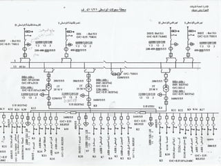
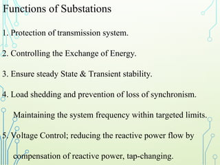


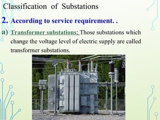

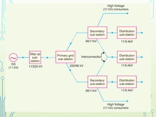
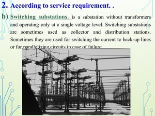


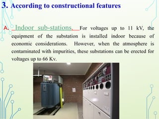

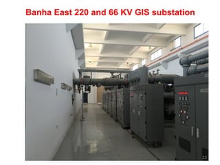

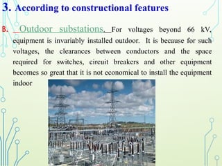
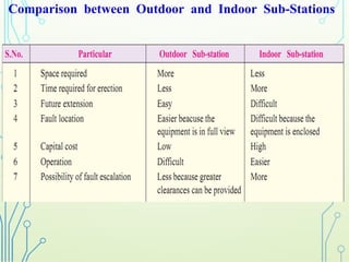
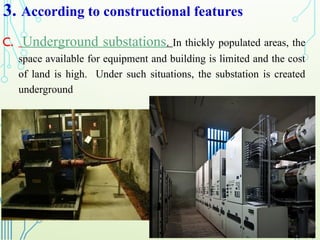

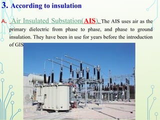
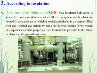


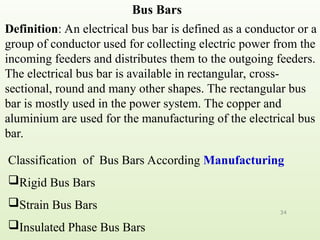


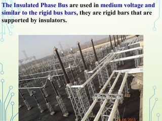
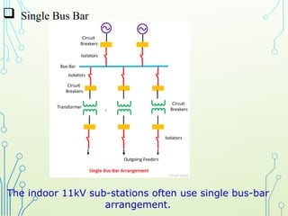


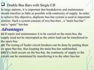


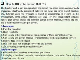

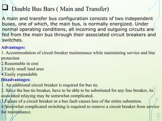
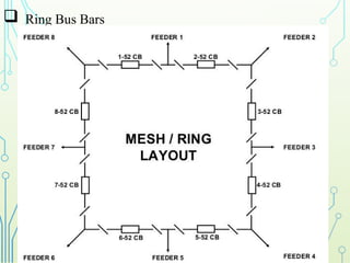
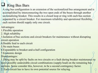
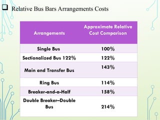
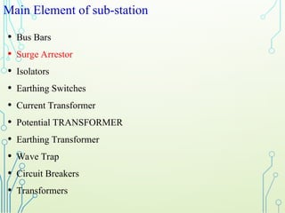

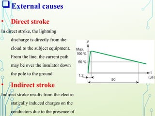
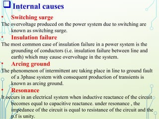
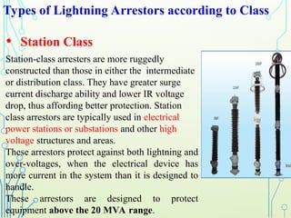
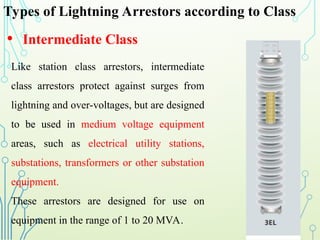
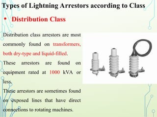

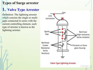
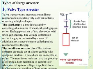
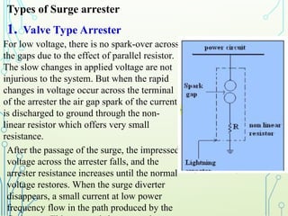
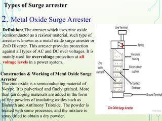
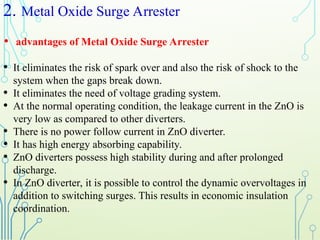

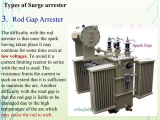


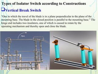


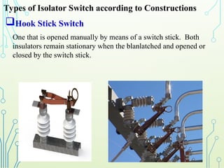

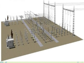


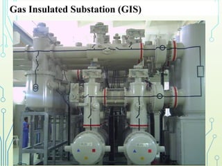
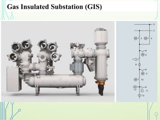
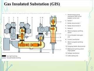
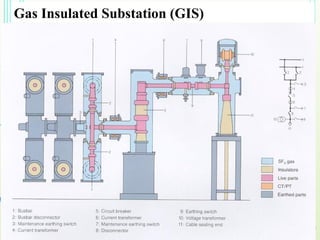


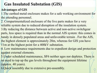


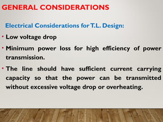
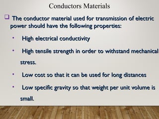
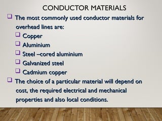

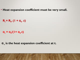


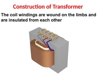
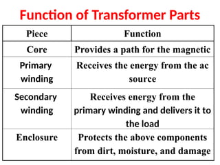
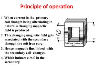
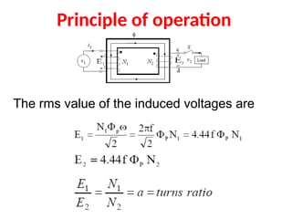


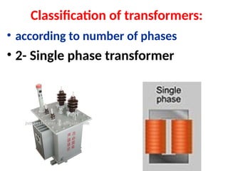
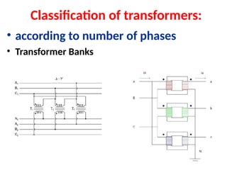
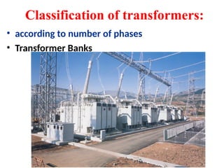

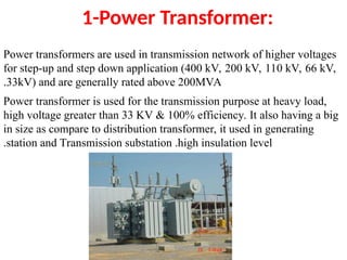

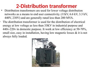
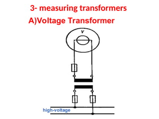
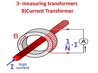


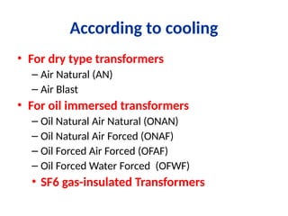

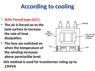
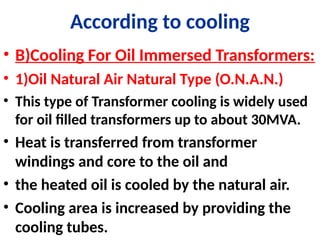


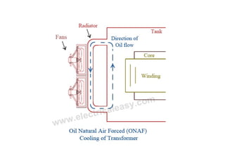

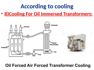
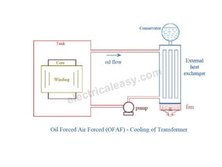

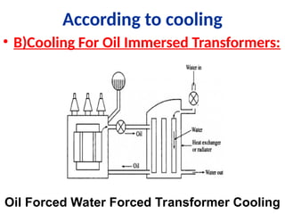
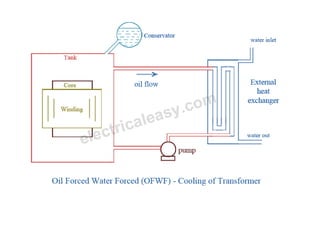
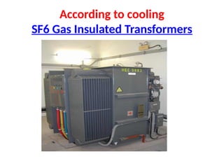


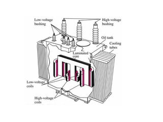

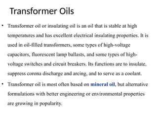


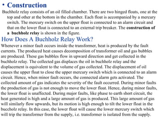
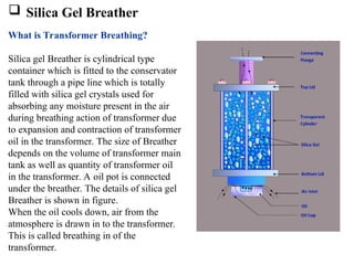


![ tap changer
Why tap changer is placed on high voltage side?
The tap changer is placed on high voltage side because:
1) The HV winding generally wound over LV
winding hence it is easier to access the HV winding
turns instead of LV winding.
2) Because of high voltage the current through the
HV winding is less compared to LV windings, hence
there is less “wear” on the tap changer contacts. Due
this low current, in on load tap changer the change over
spark will be less.
Tap changers exist in two primary types,[1] no load tap changers
(NLTC) which must be de-energized before the turn ratio is adjusted
and on load tap changers (OLTC) which may adjust their turn ratio
during operation.](https://image.slidesharecdn.com/electricalmaintenance1-250708102642-7a128c95/85/Electrical-maintenance-process-f-1-ppt-162-320.jpg)
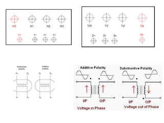

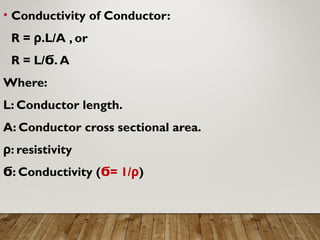
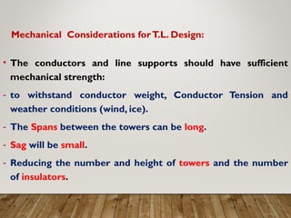
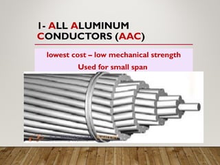

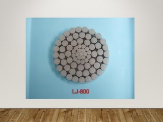


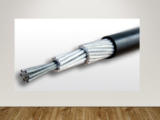


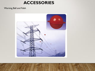


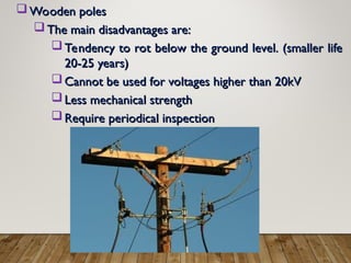


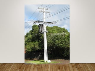
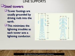

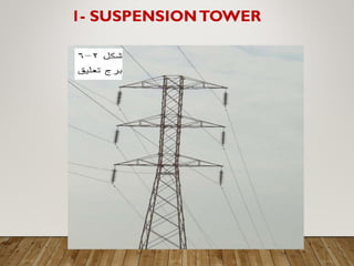


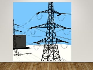

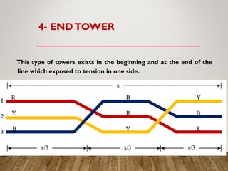
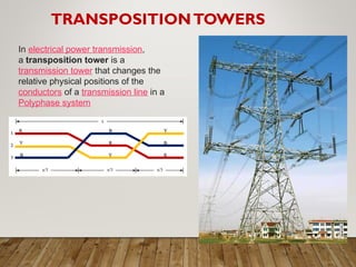
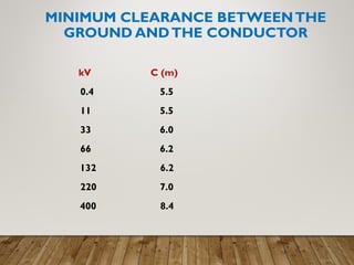


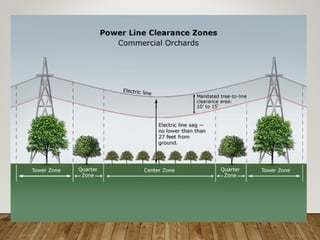


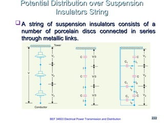
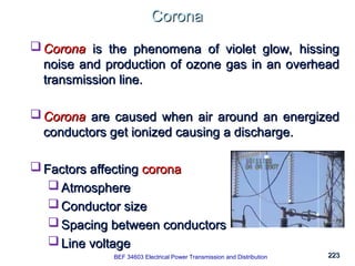


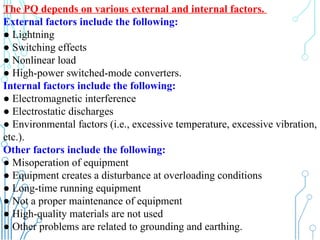

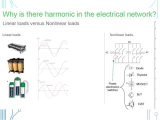

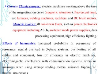
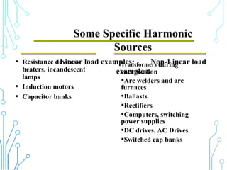
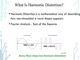

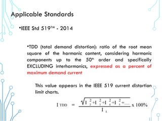


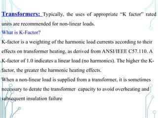


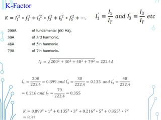


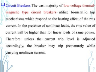

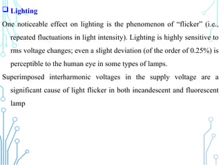
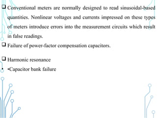


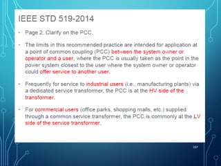
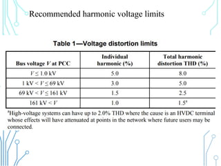


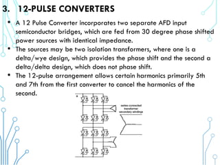
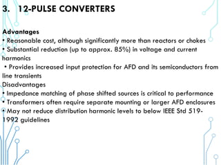

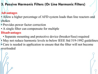


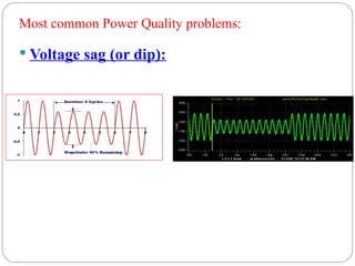

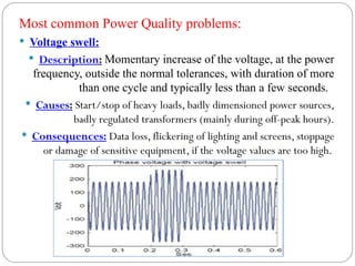

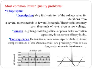
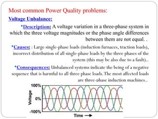

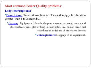

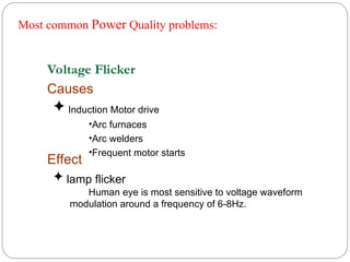


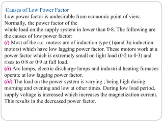
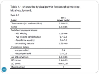


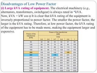
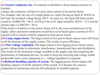

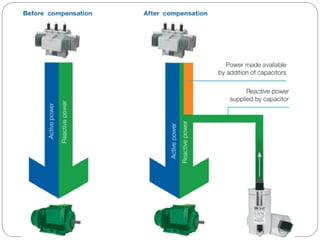
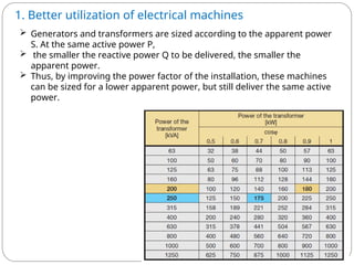

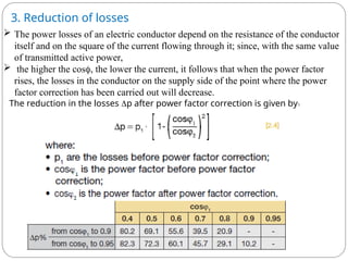

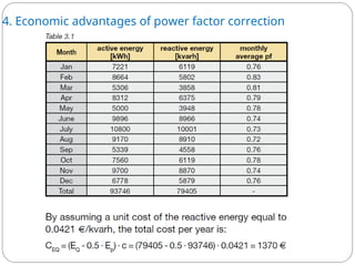
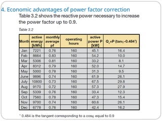
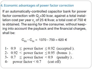


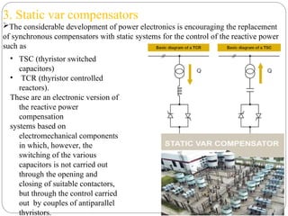
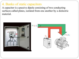


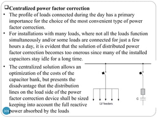
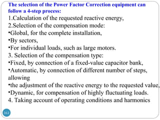

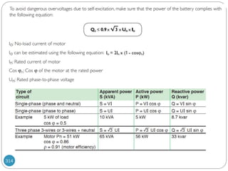


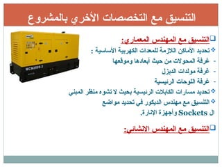
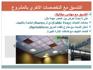

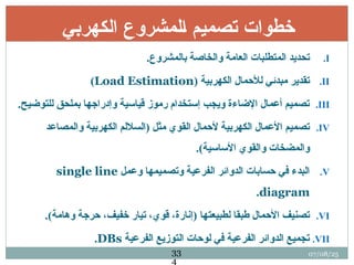


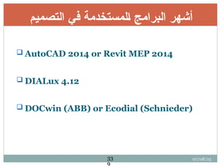


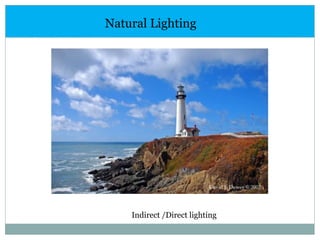
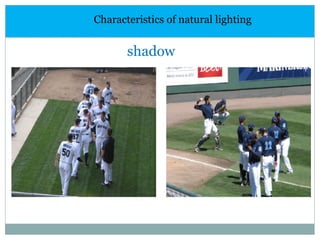
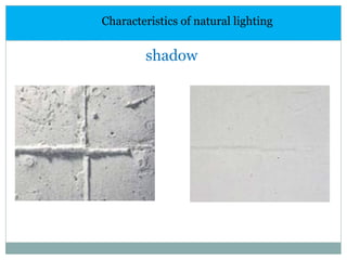


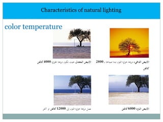


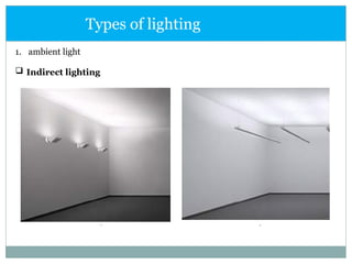
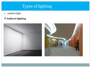
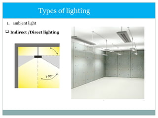
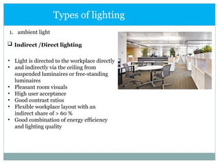


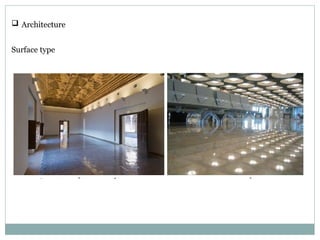


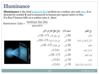

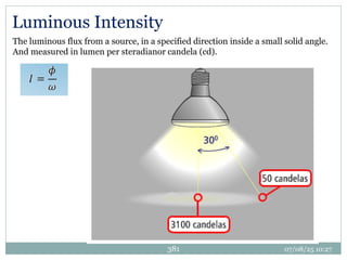
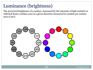
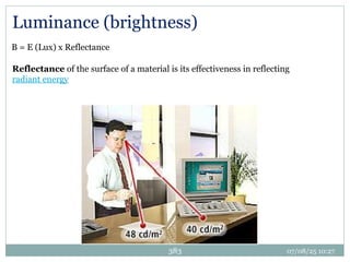
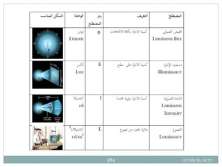

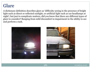

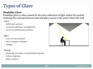


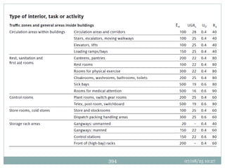

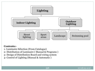

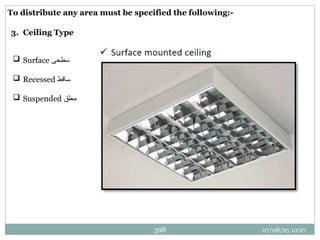
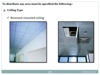


![Fluid_level_measurement_[2305843009284379220][1].ppt](https://cdn.slidesharecdn.com/ss_thumbnails/fluidlevelmeasurement23058430092843792201-250908081253-b0686685-thumbnail.jpg?width=640&height=640&fit=bounds)


