This document covers fundamental circuit analysis concepts including:
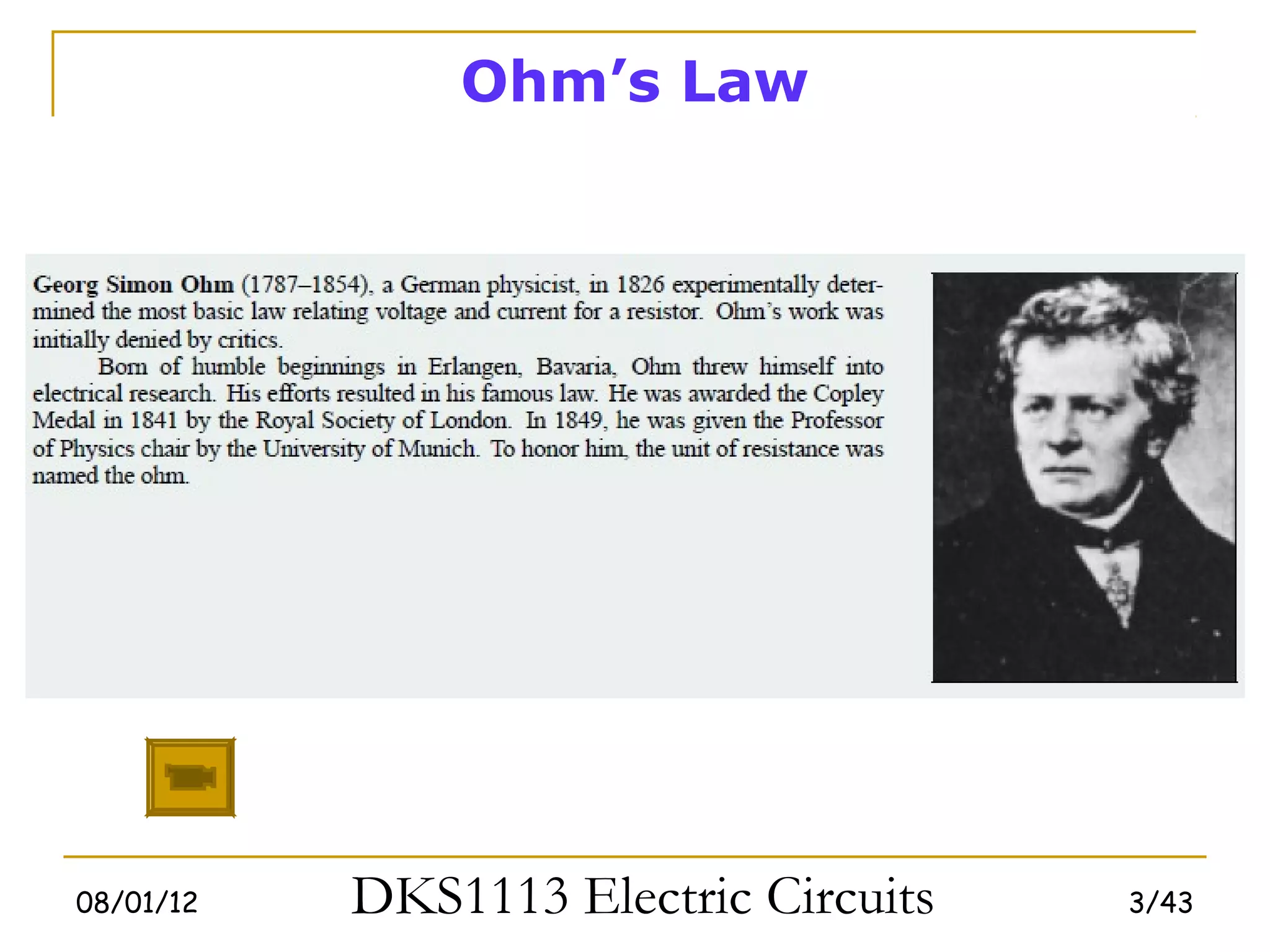
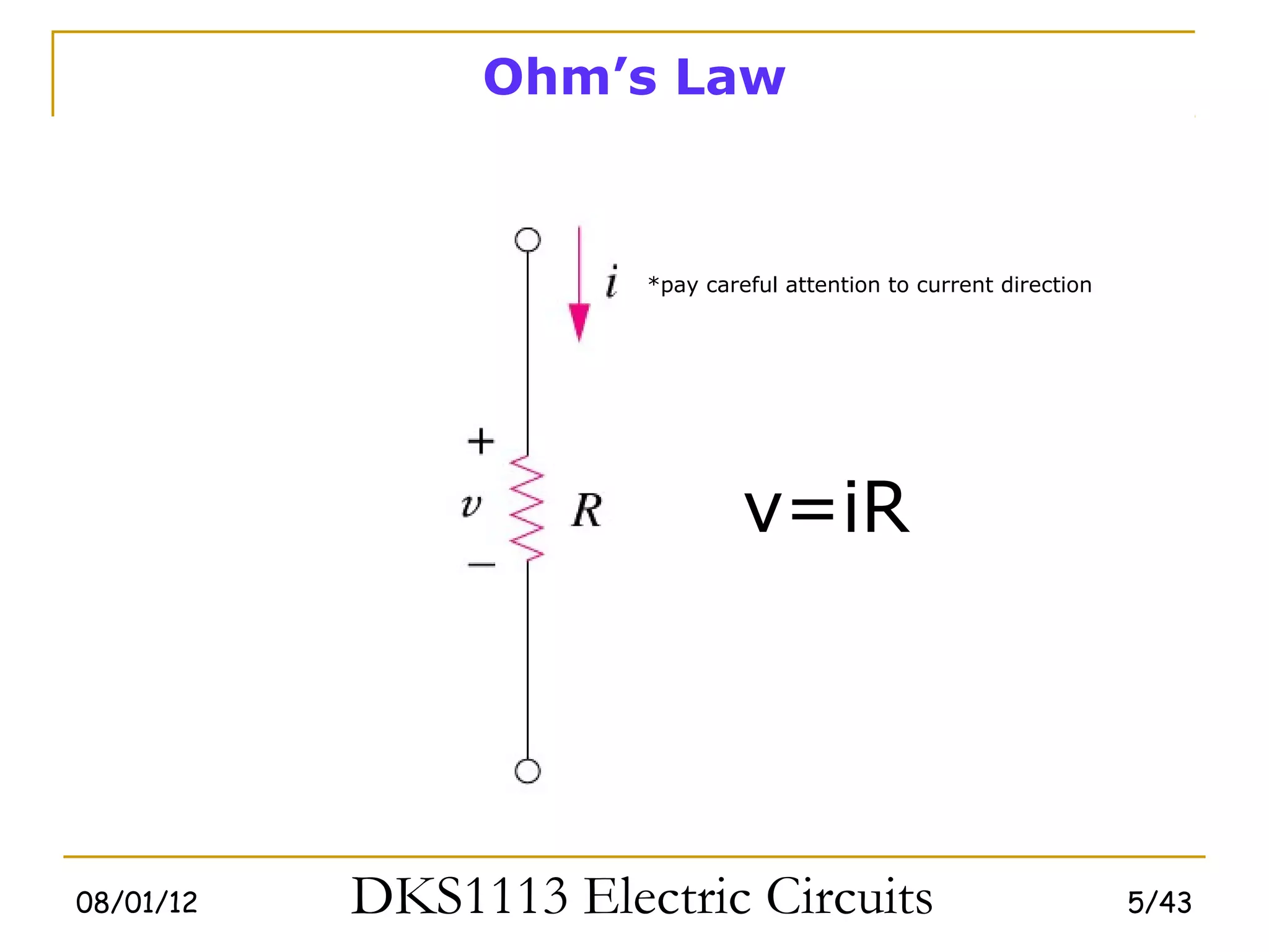
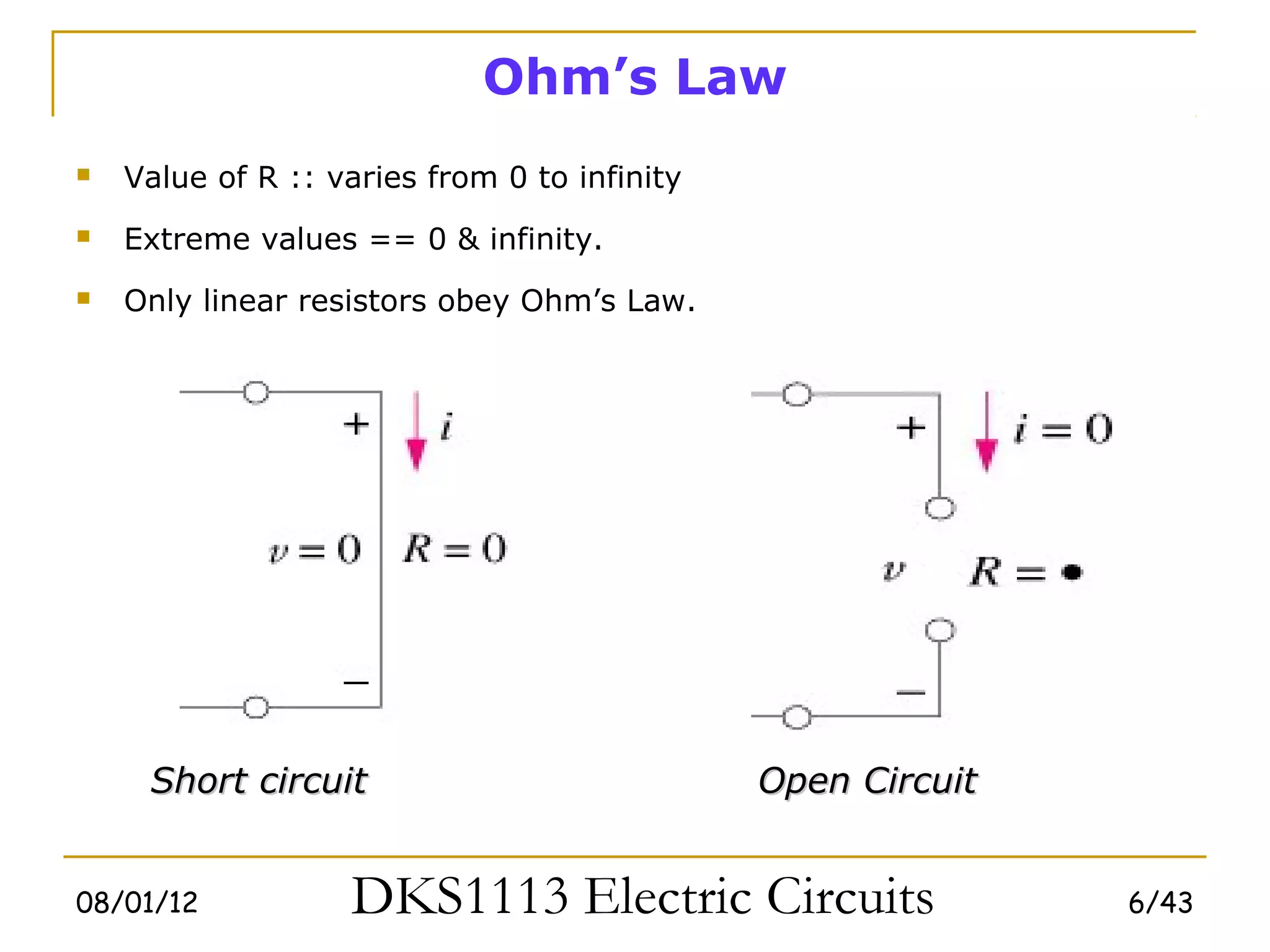
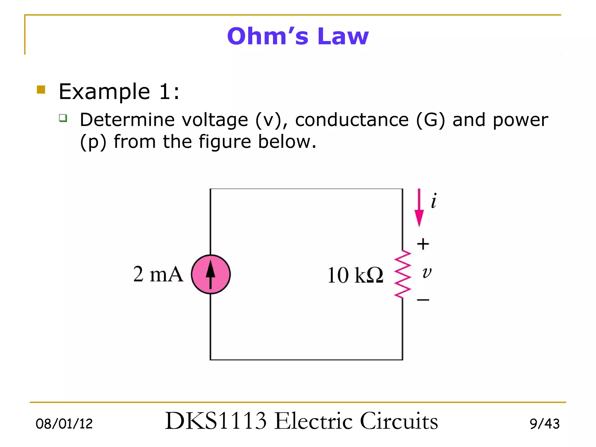
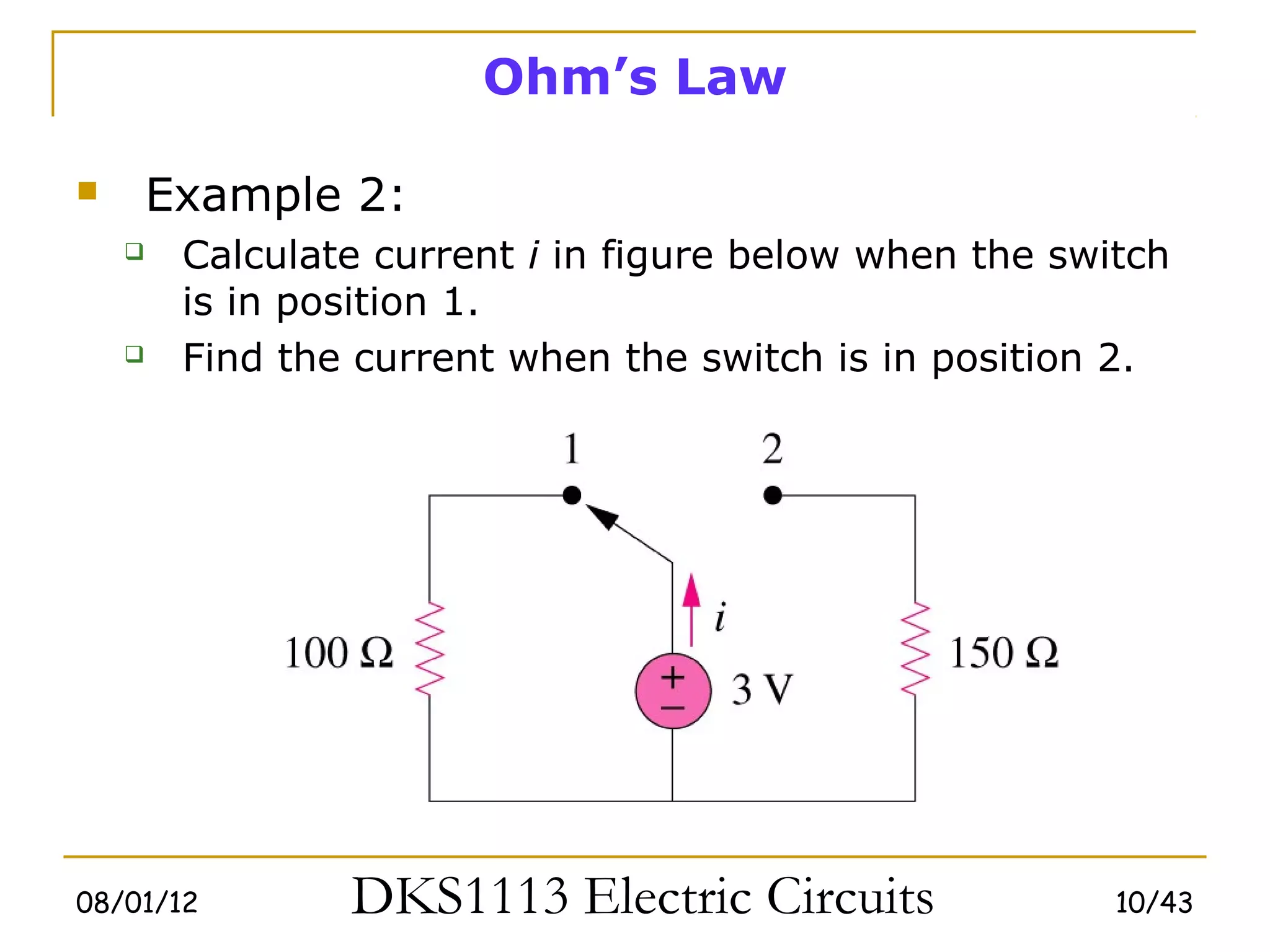
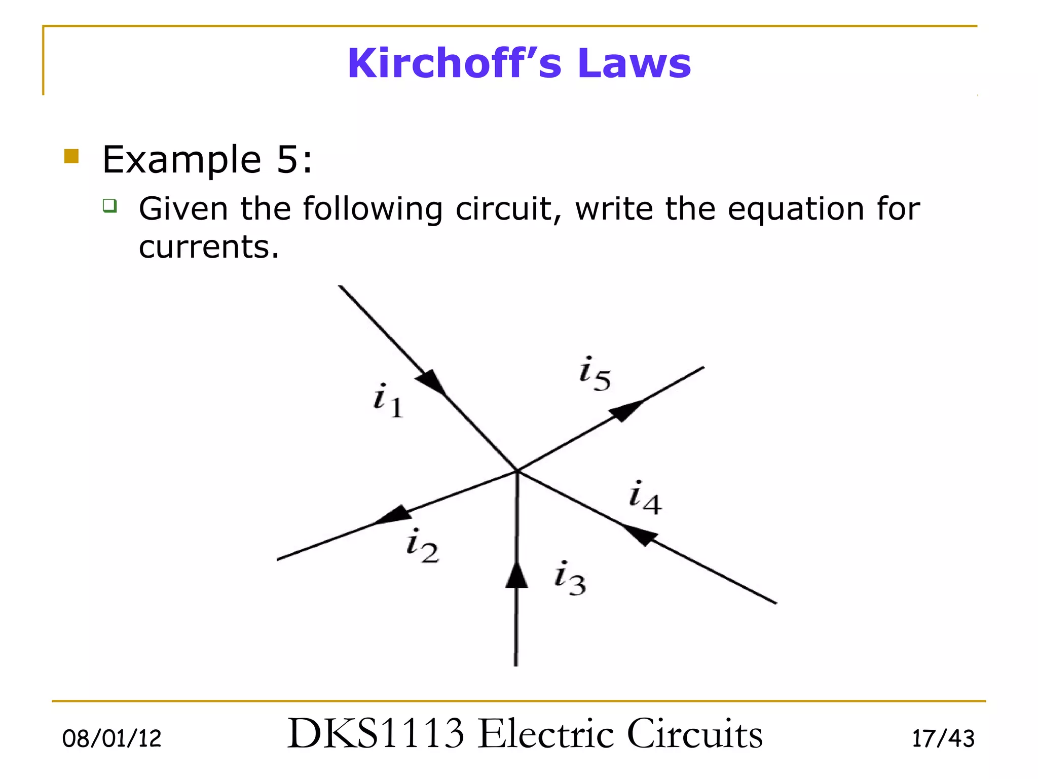
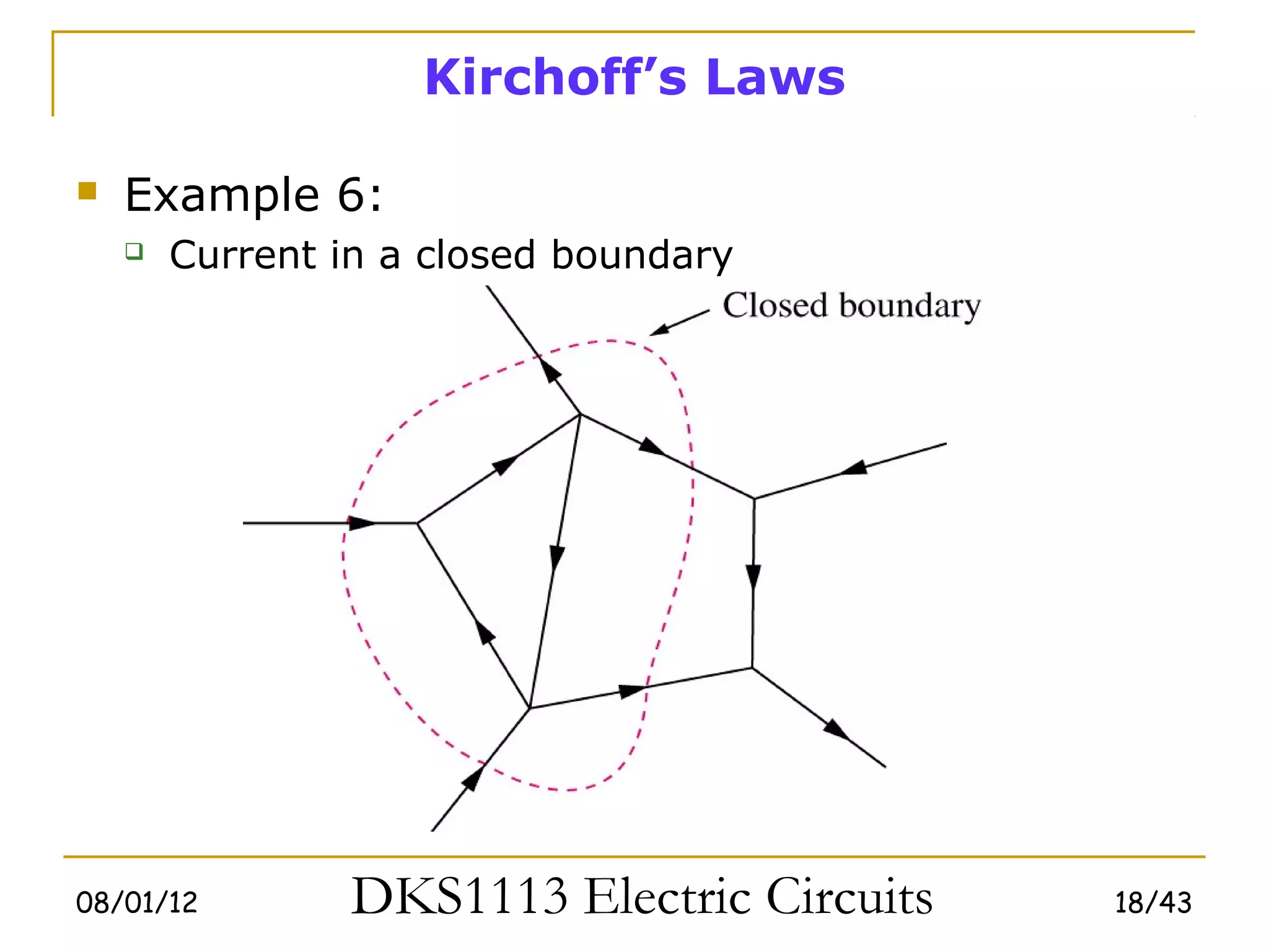
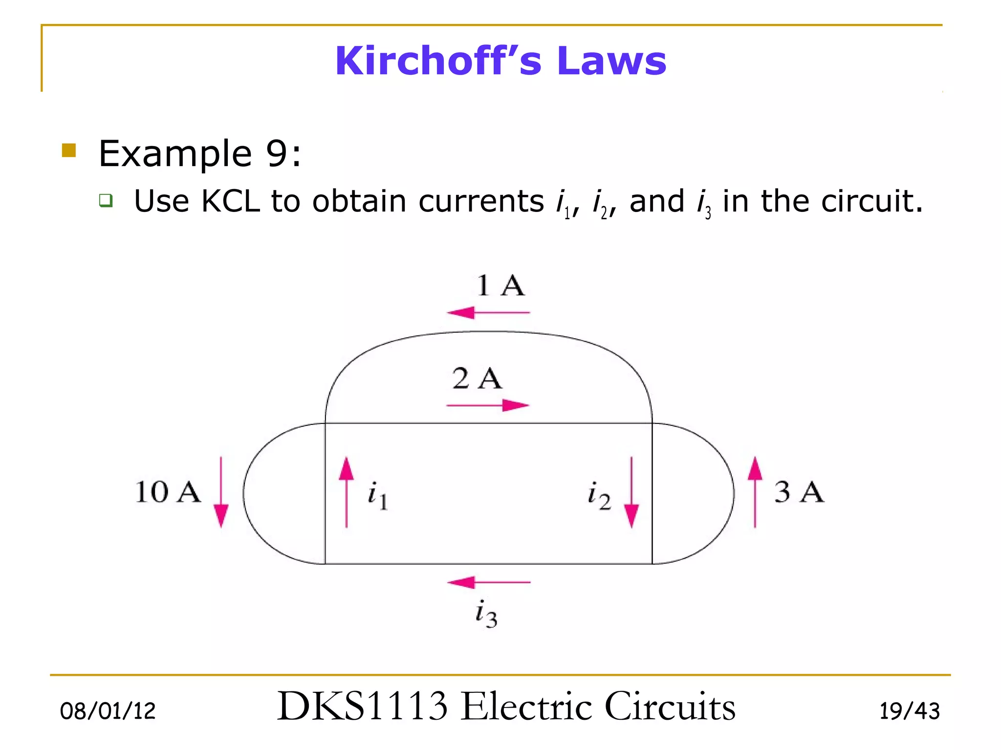
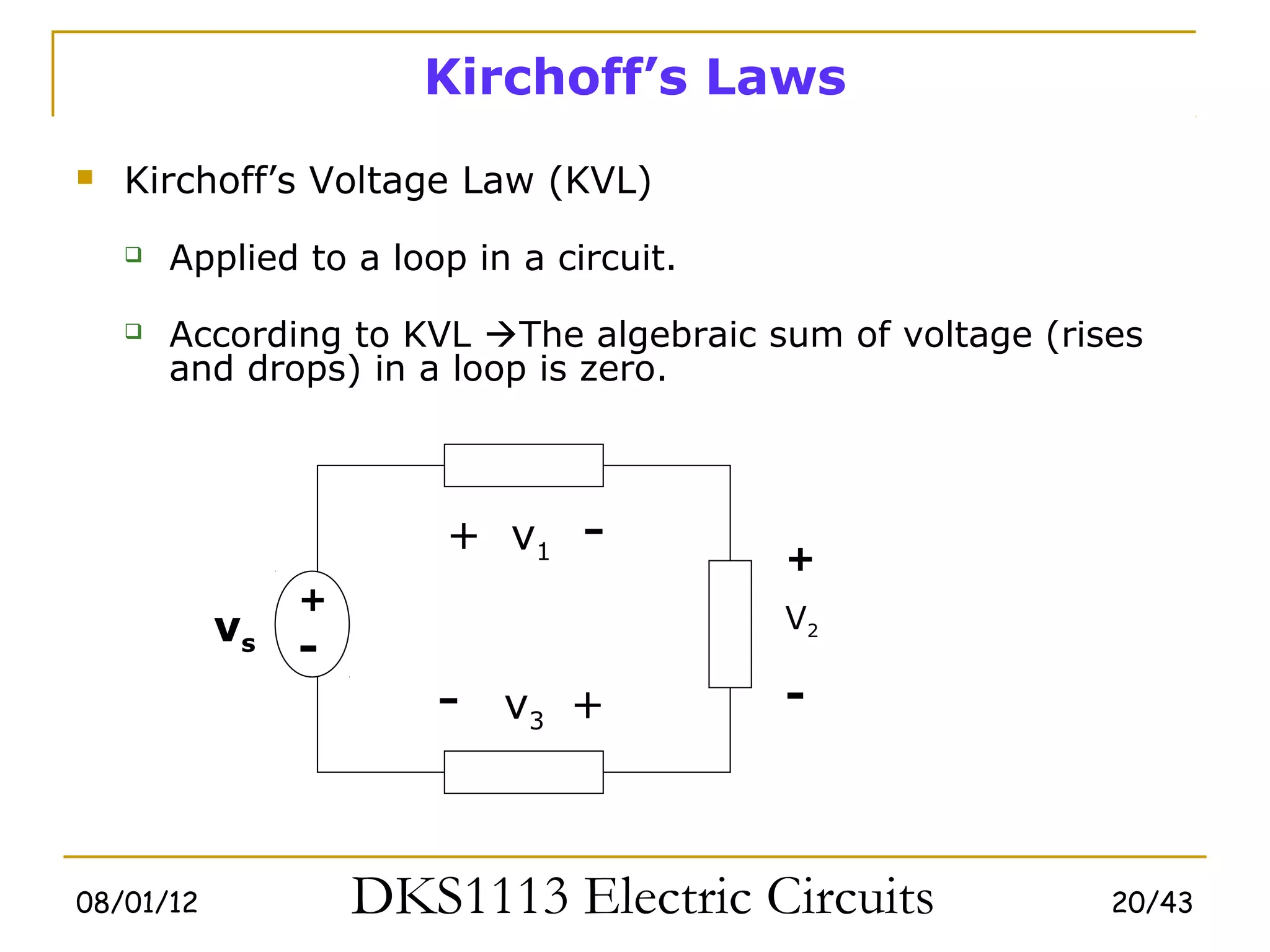
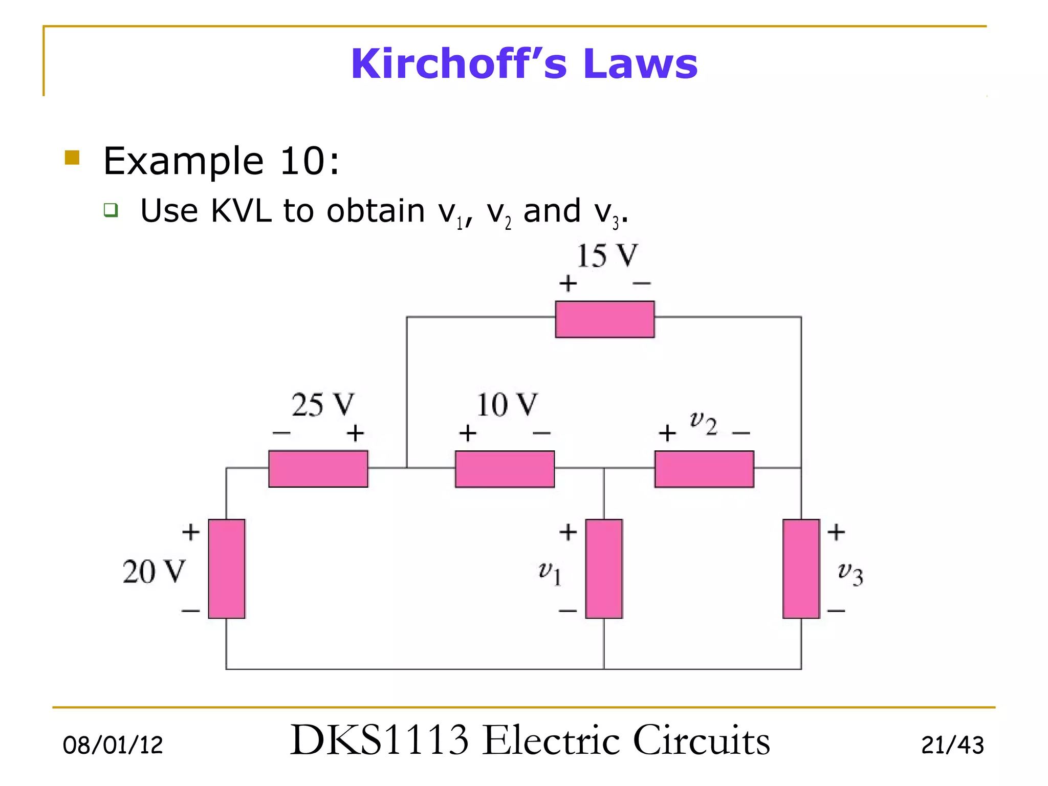
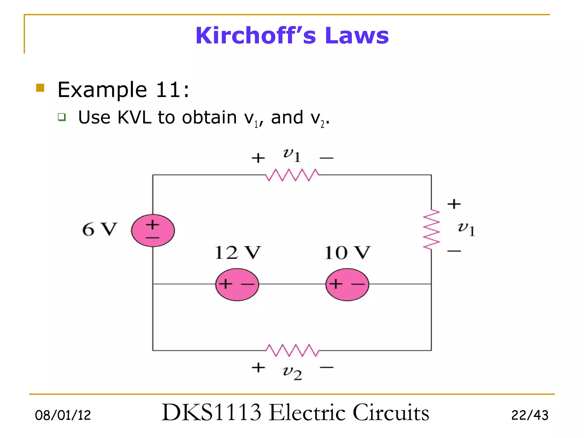
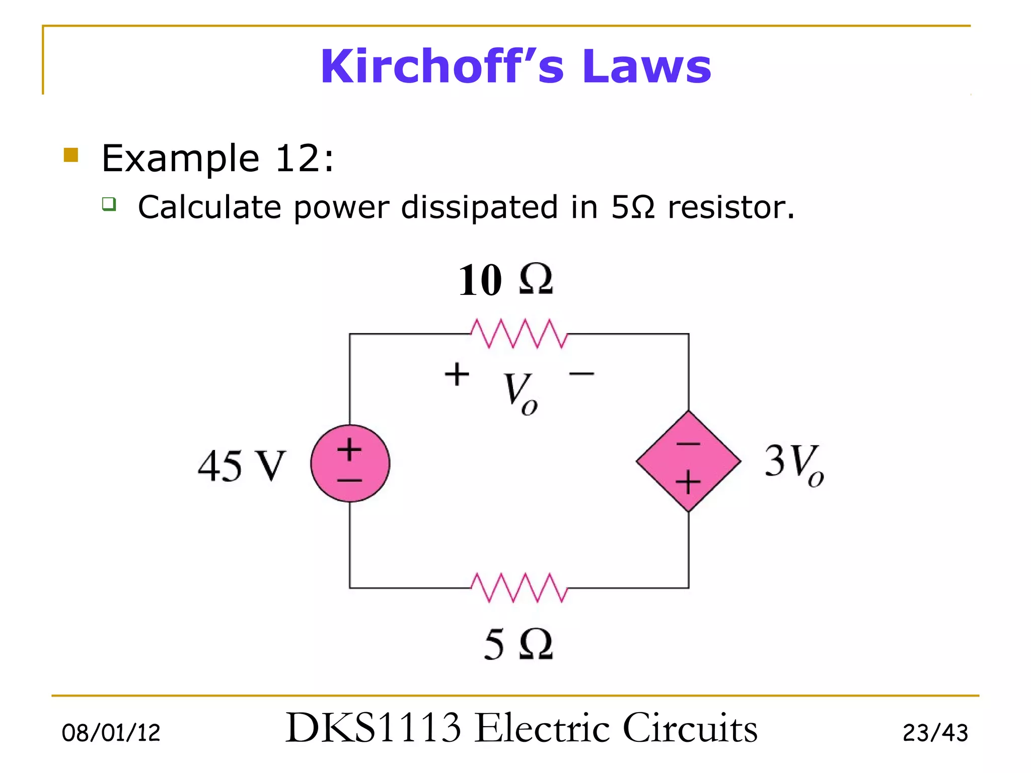
1) Ohm's law defines the relationship between current, voltage, and resistance in a circuit. Kirchoff's laws (KVL and KCL) are also introduced.
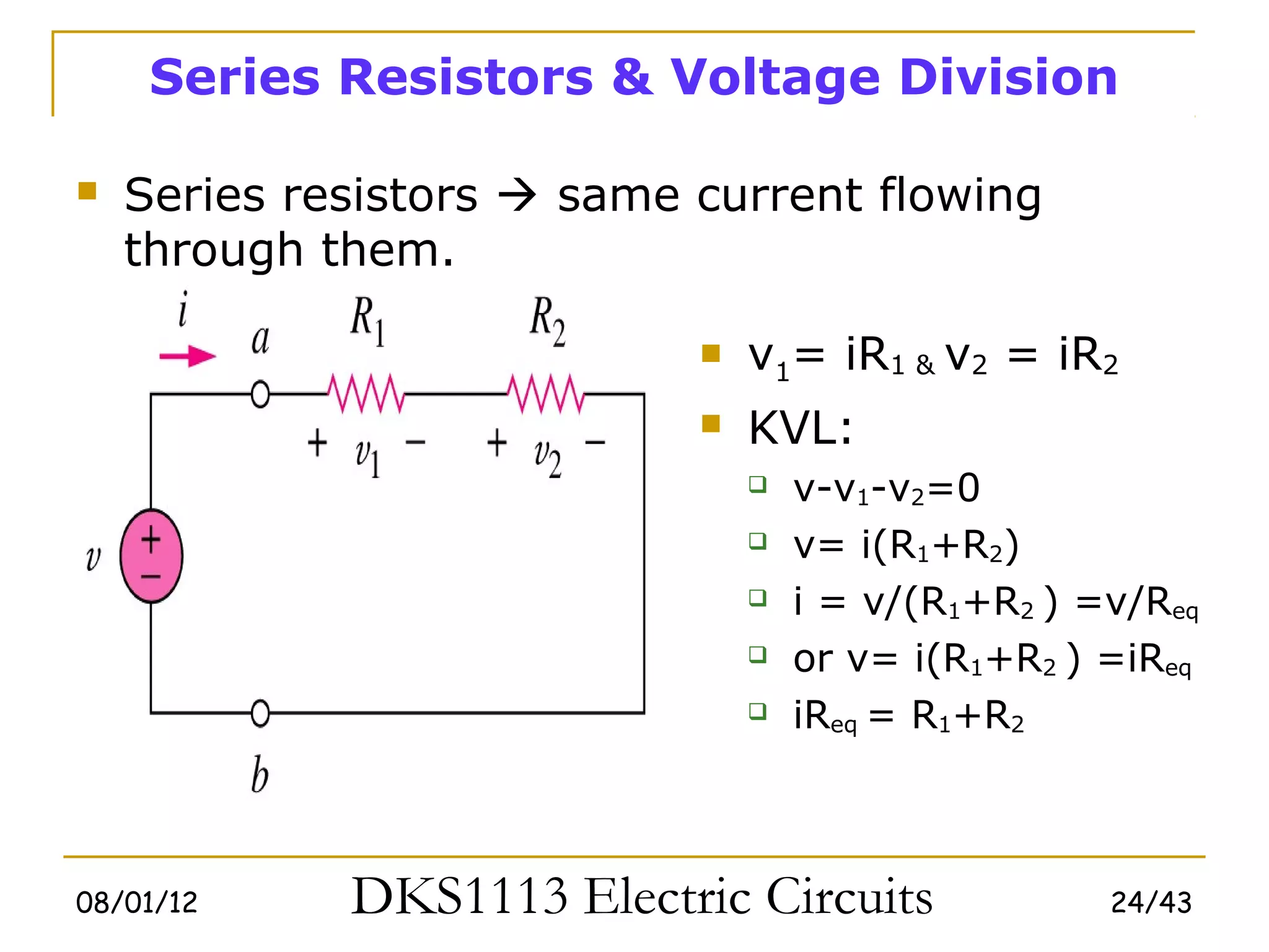
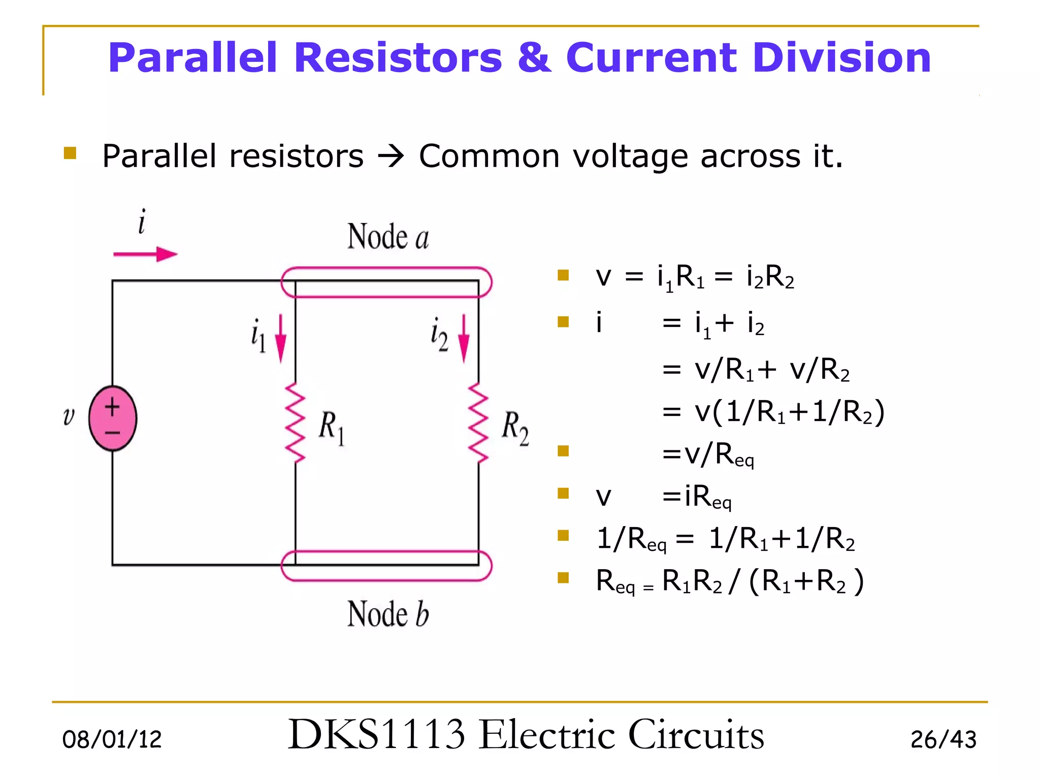
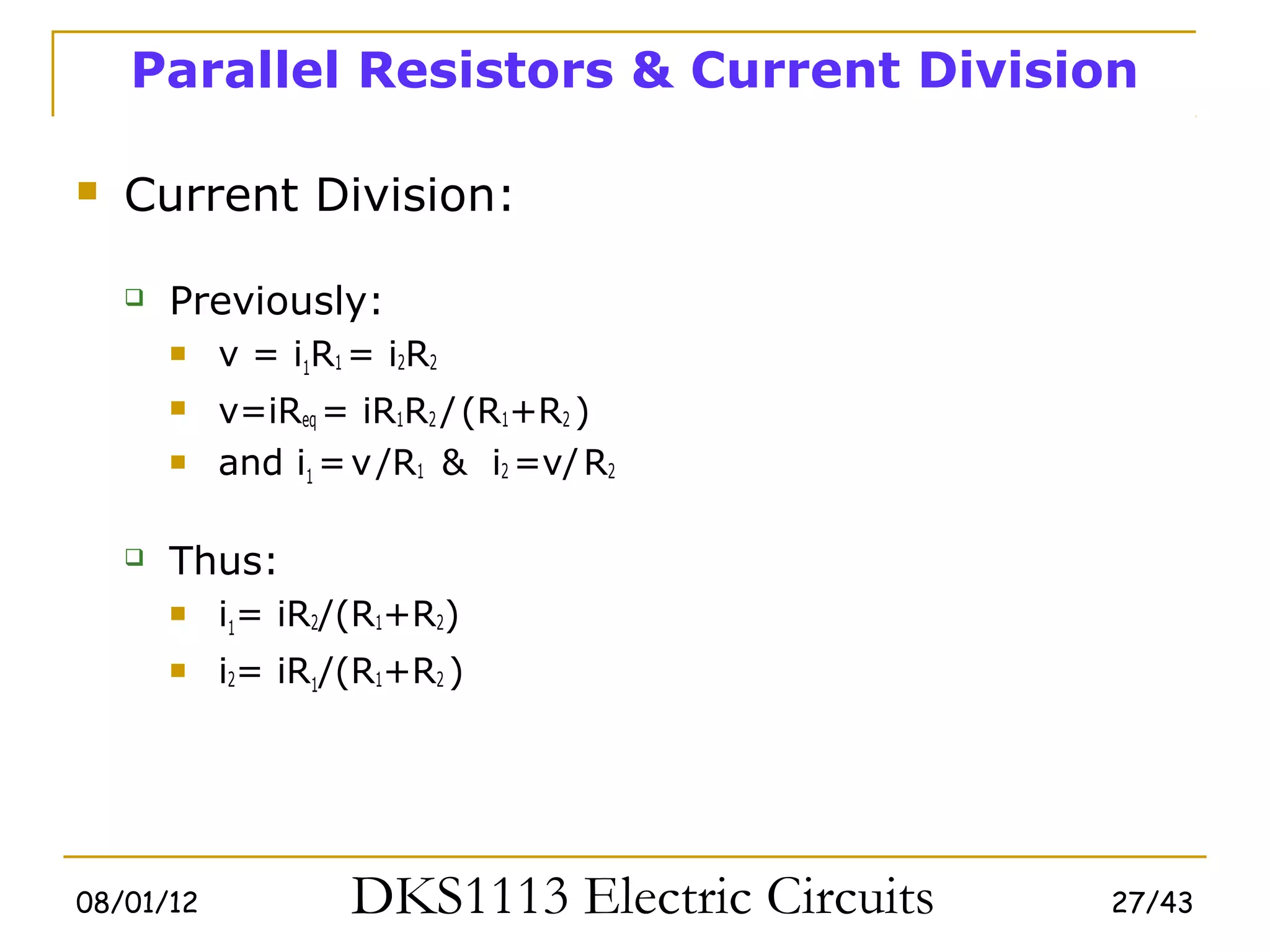
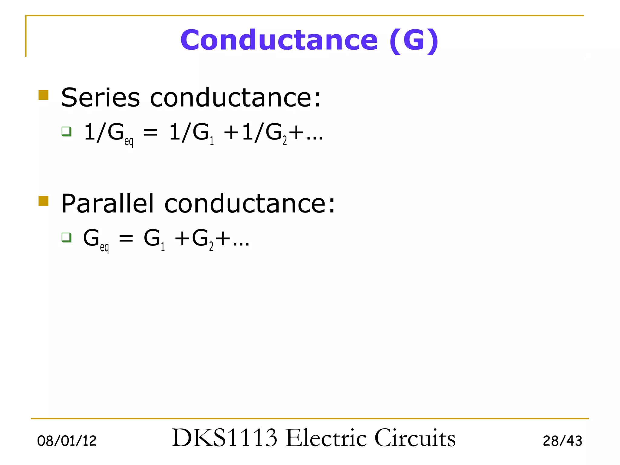
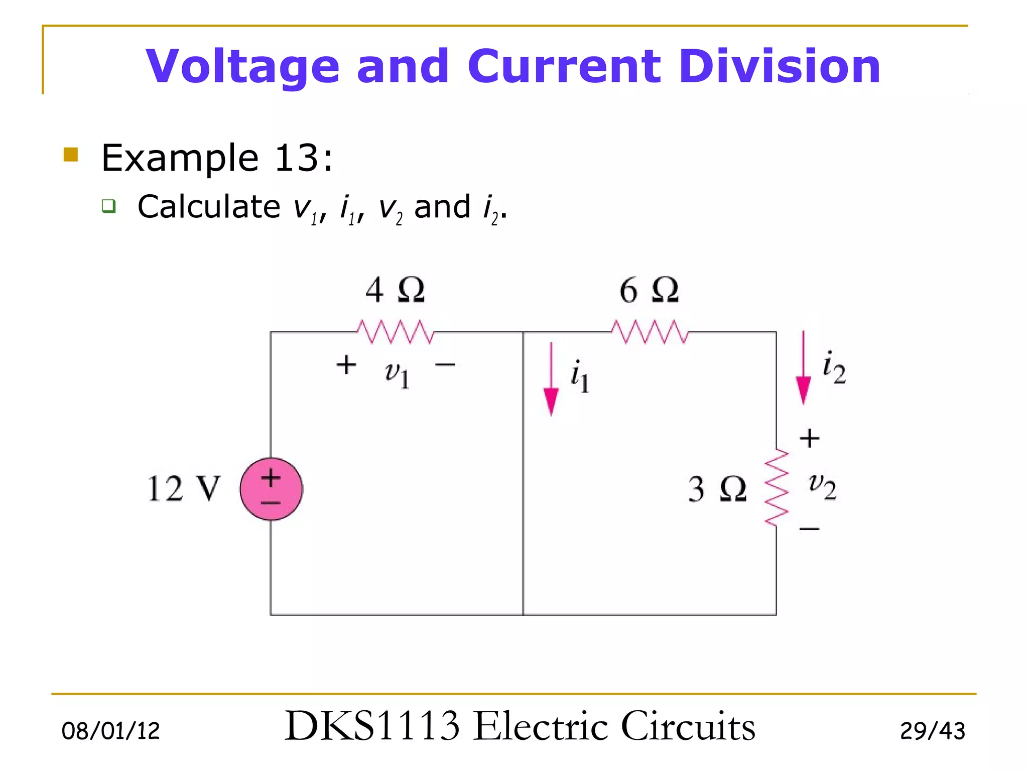
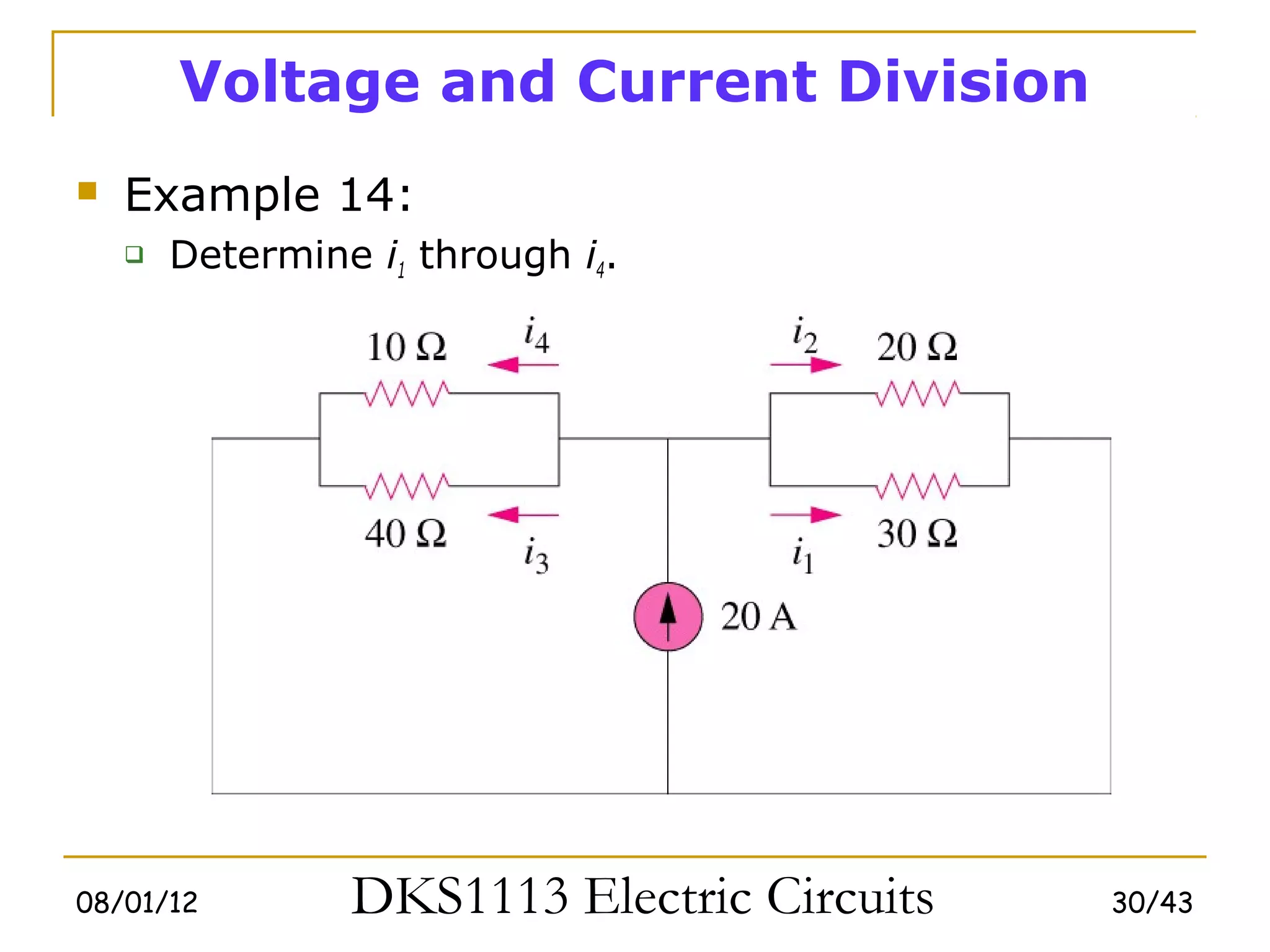
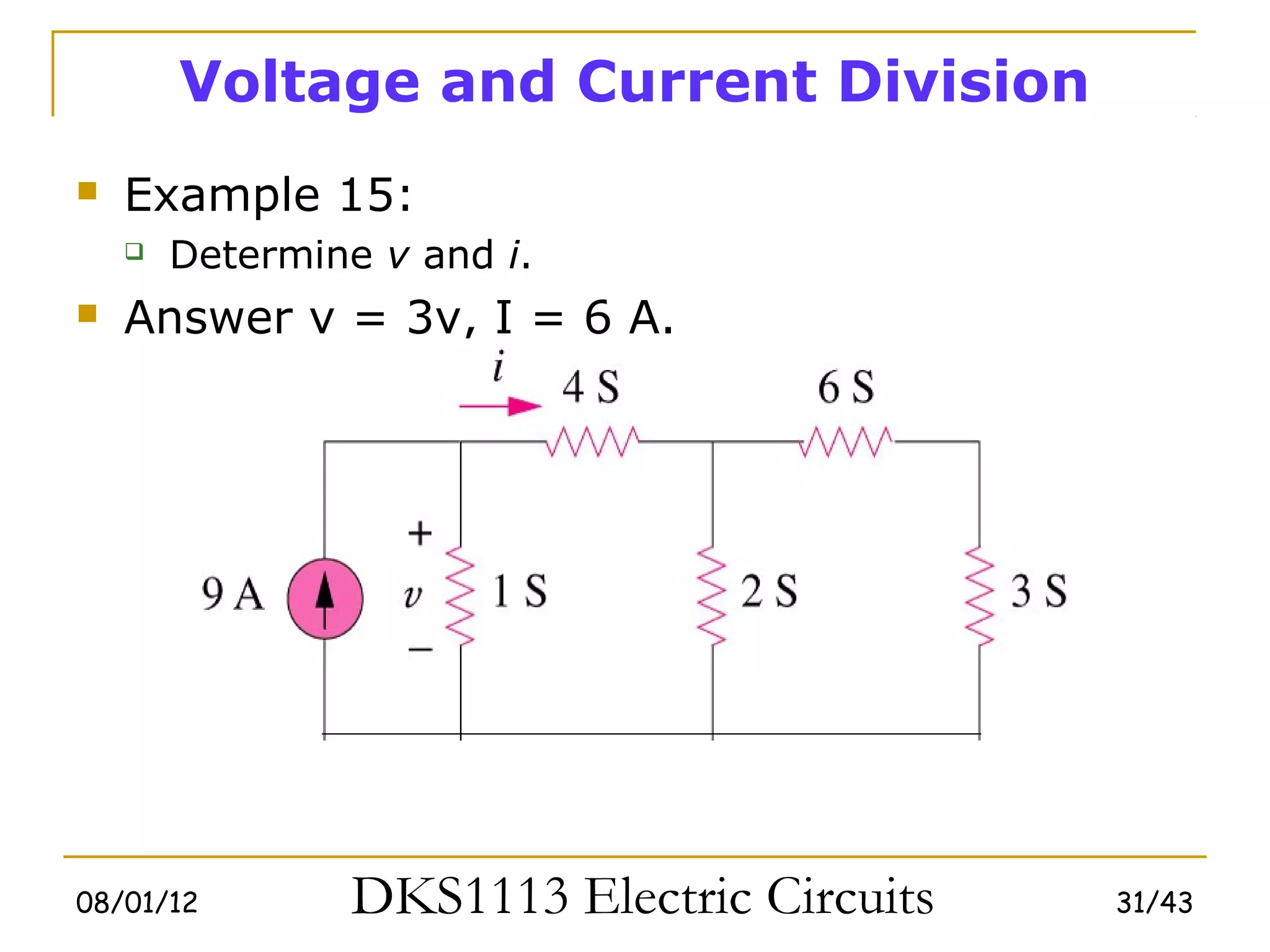
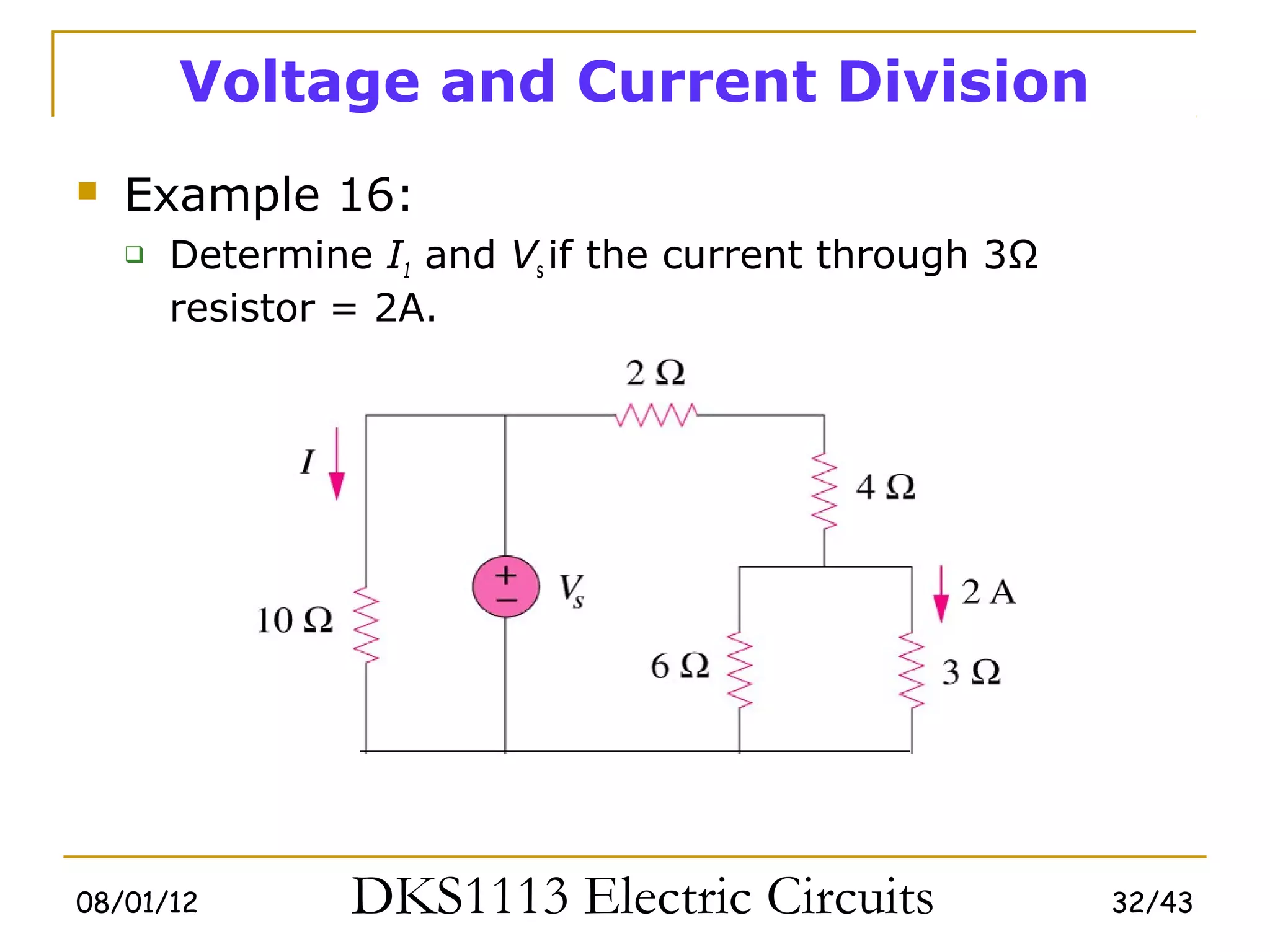
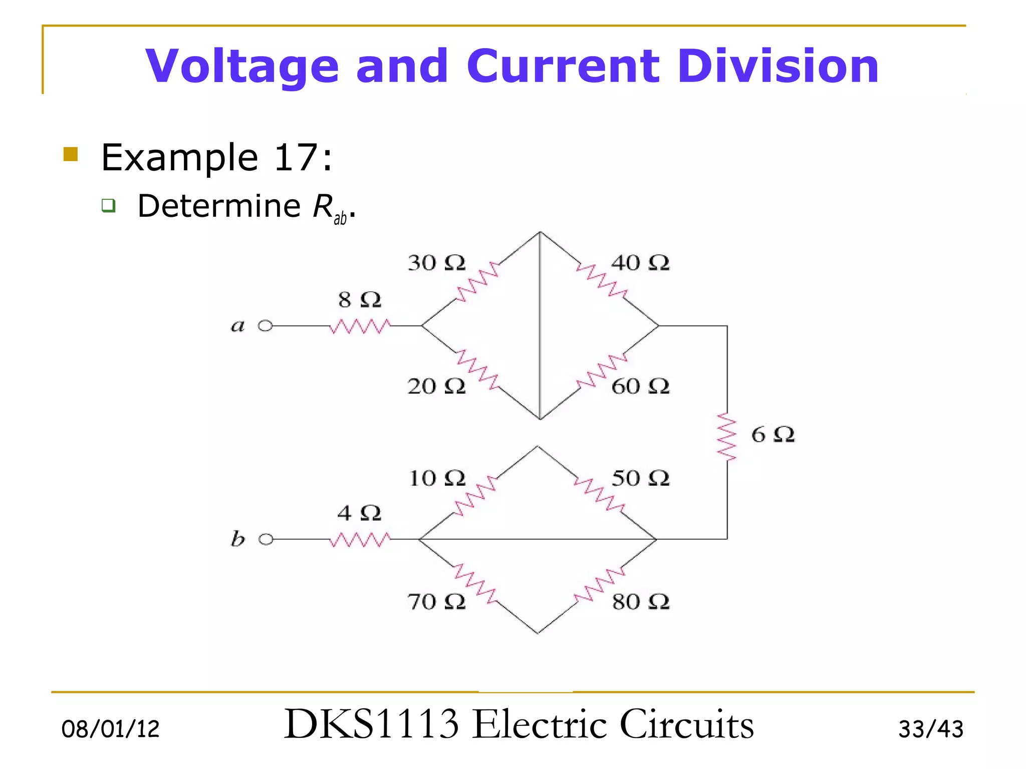
2) Series and parallel resistor combinations are examined along with voltage and current division techniques.
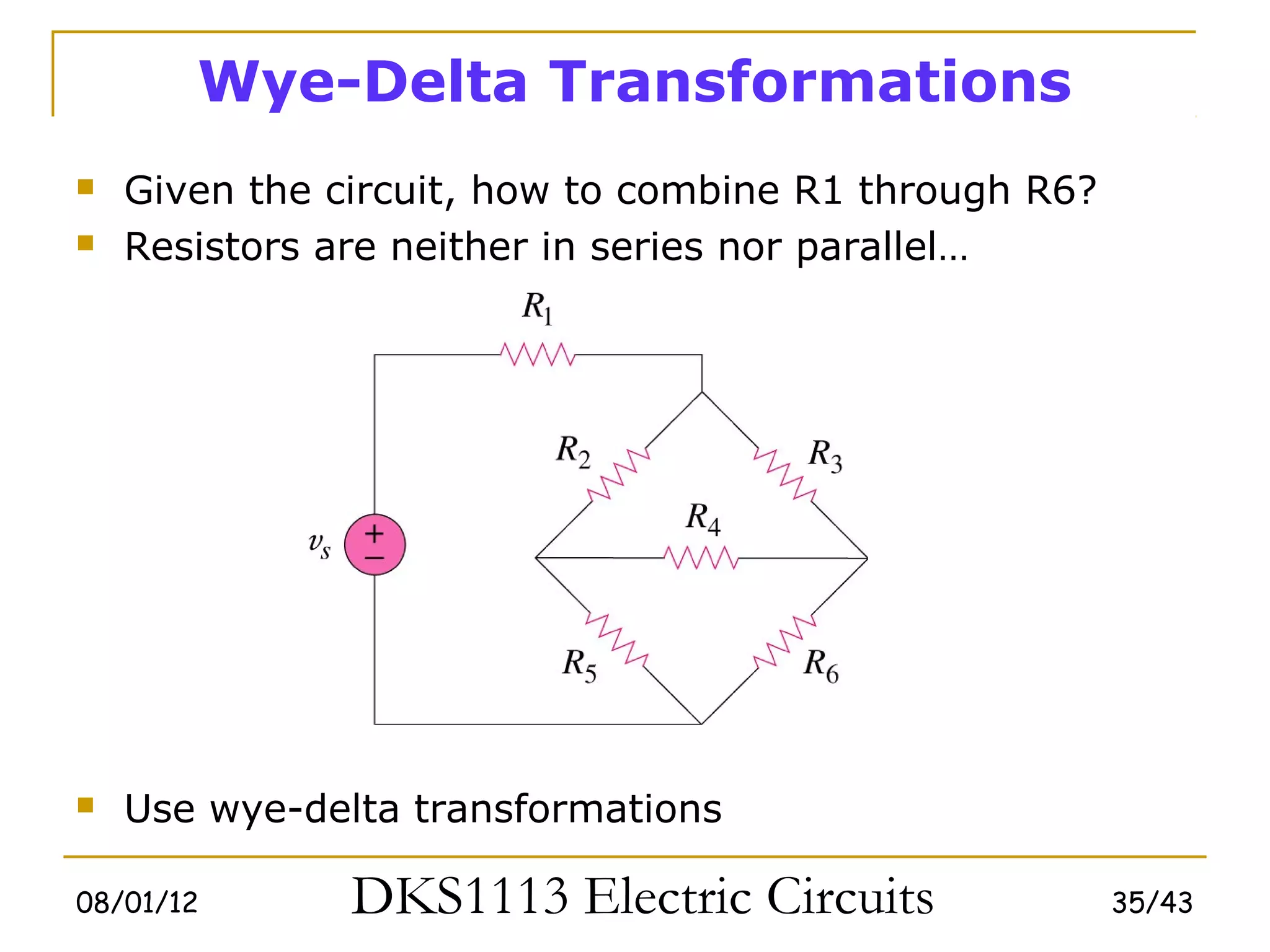
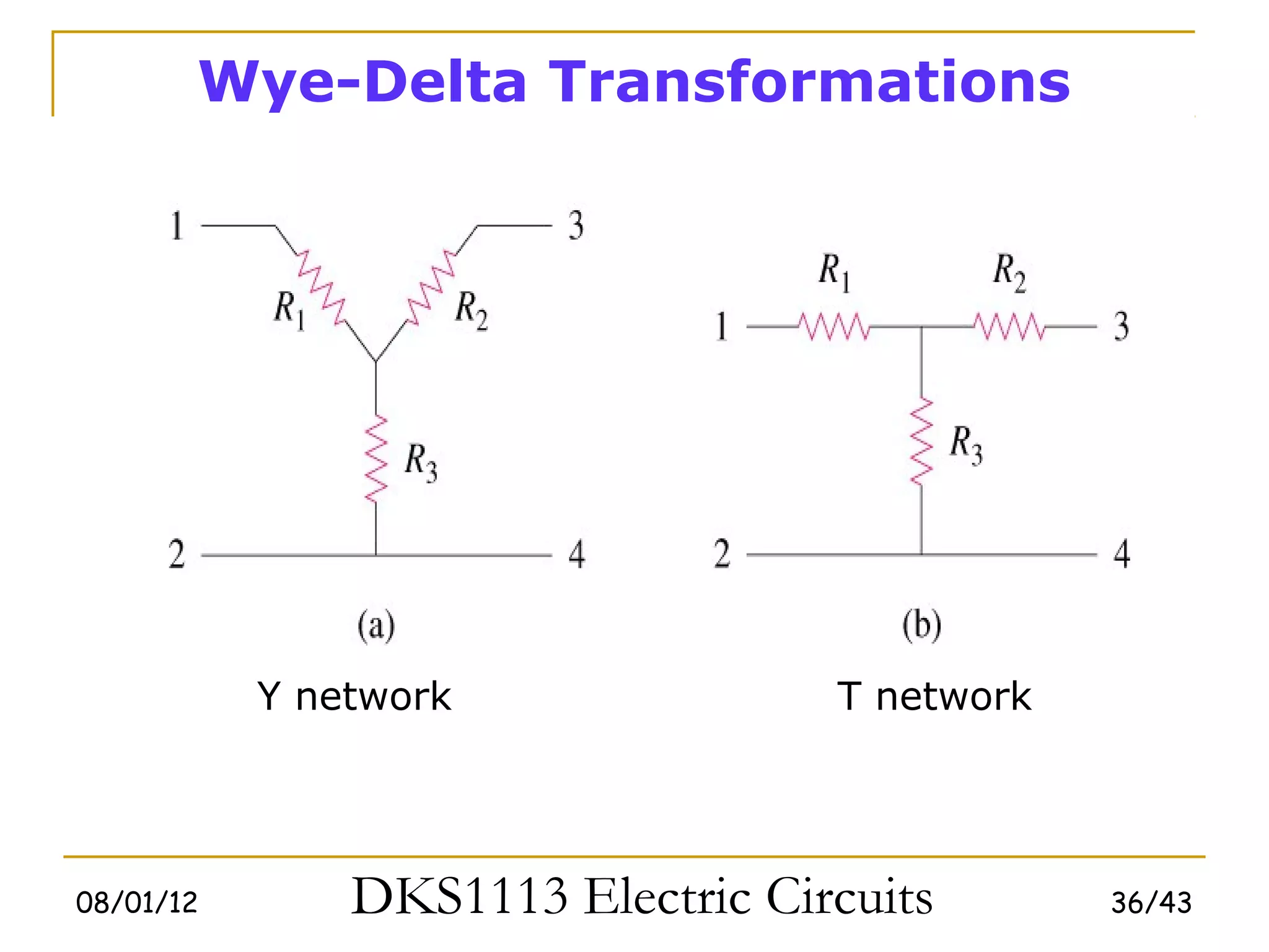
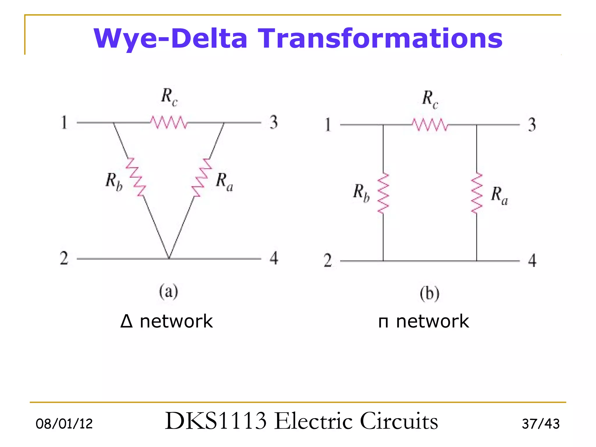
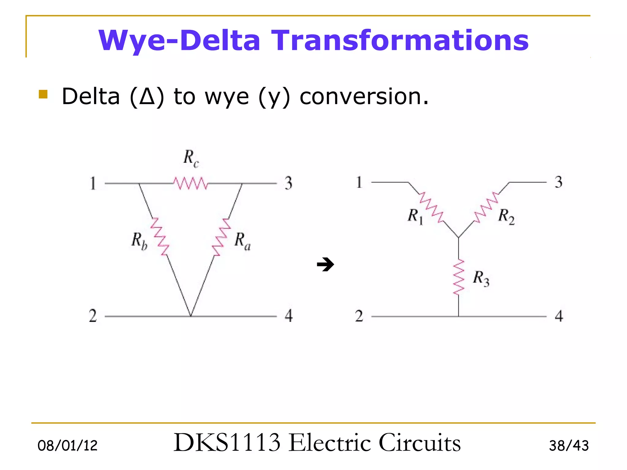
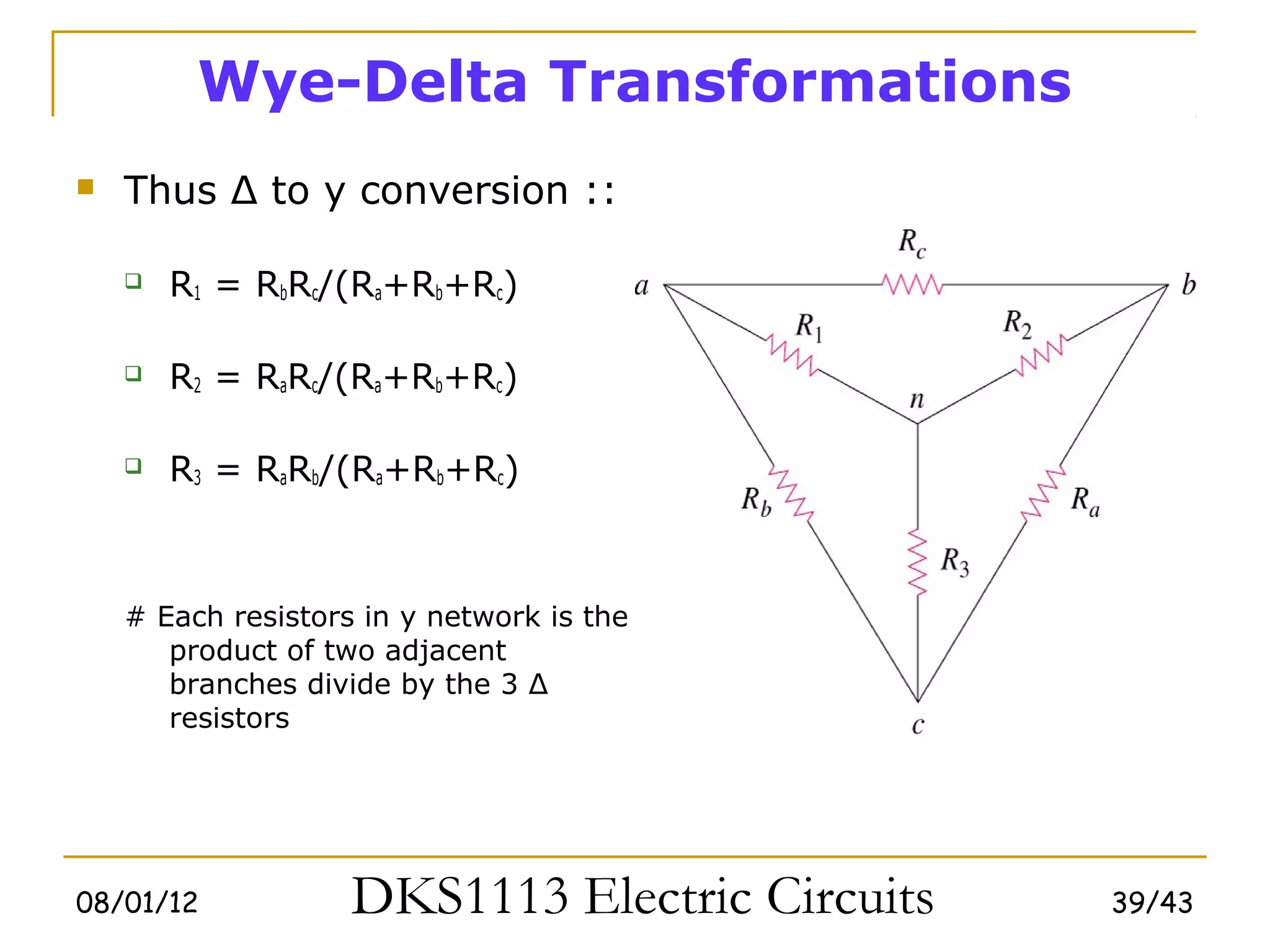
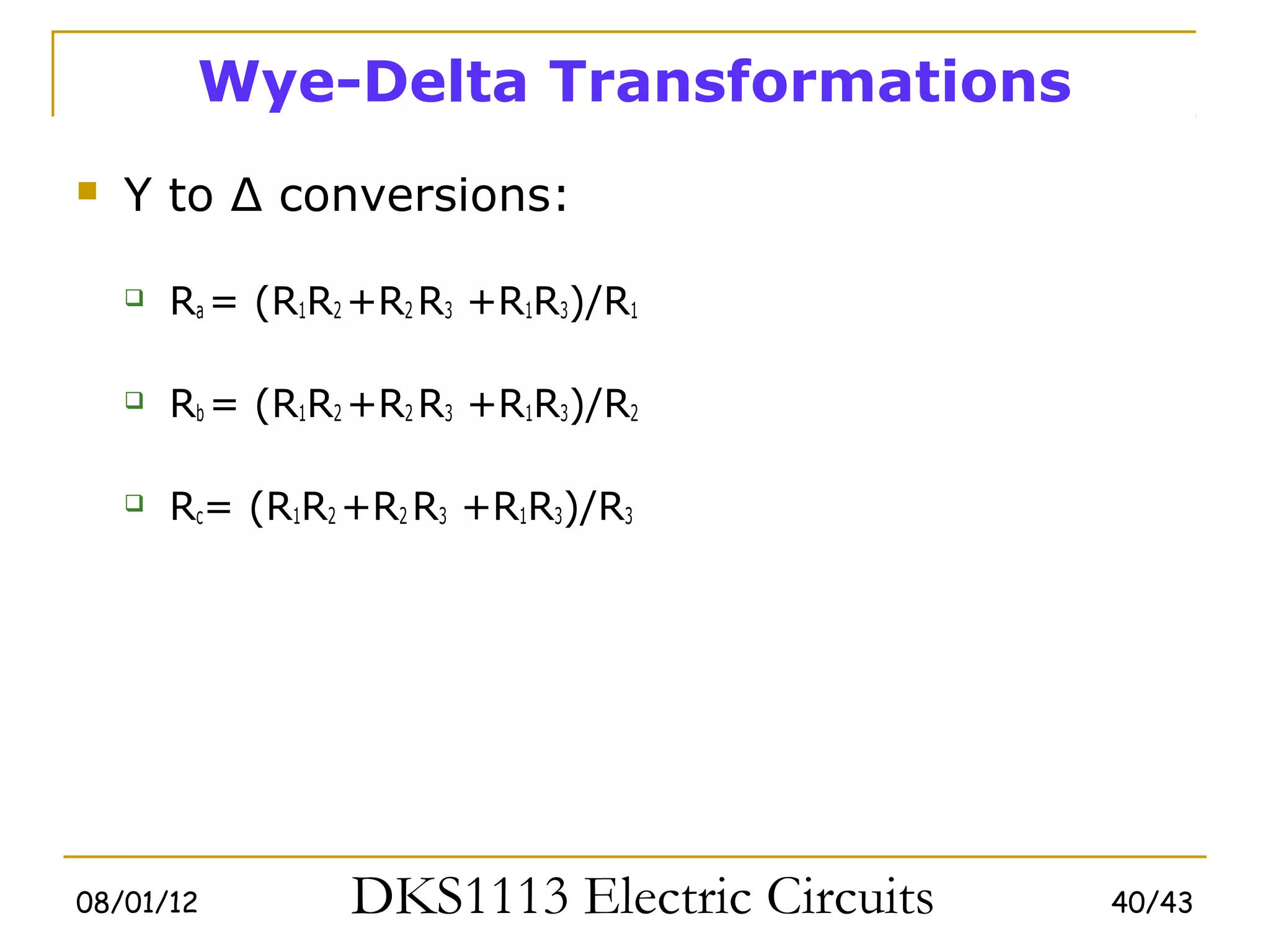
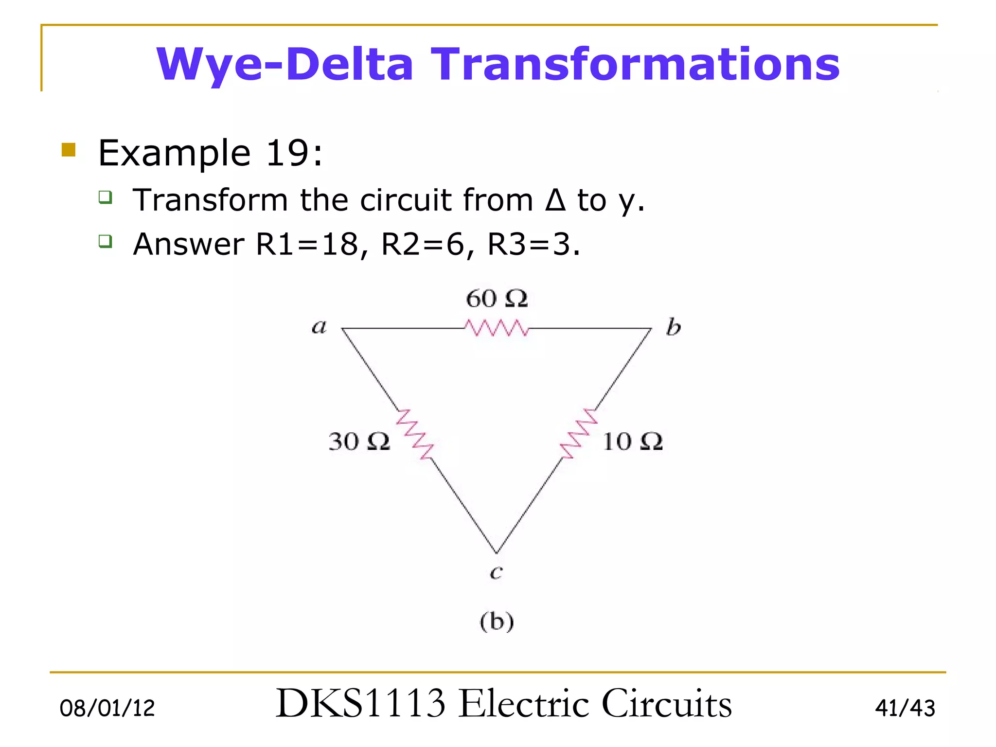
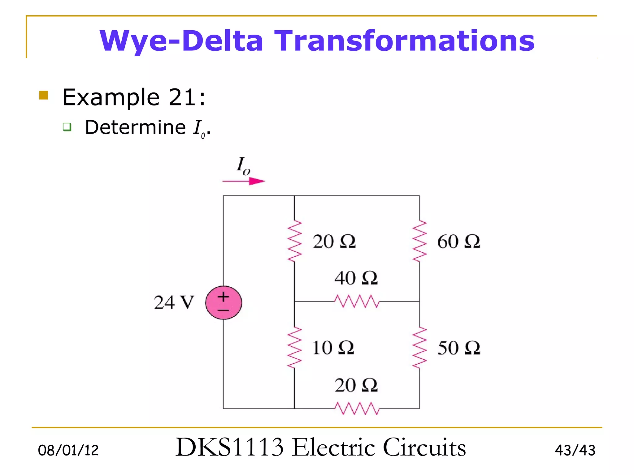
3) Wye-delta transformations allow the analysis of resistor networks that are neither purely series nor parallel.