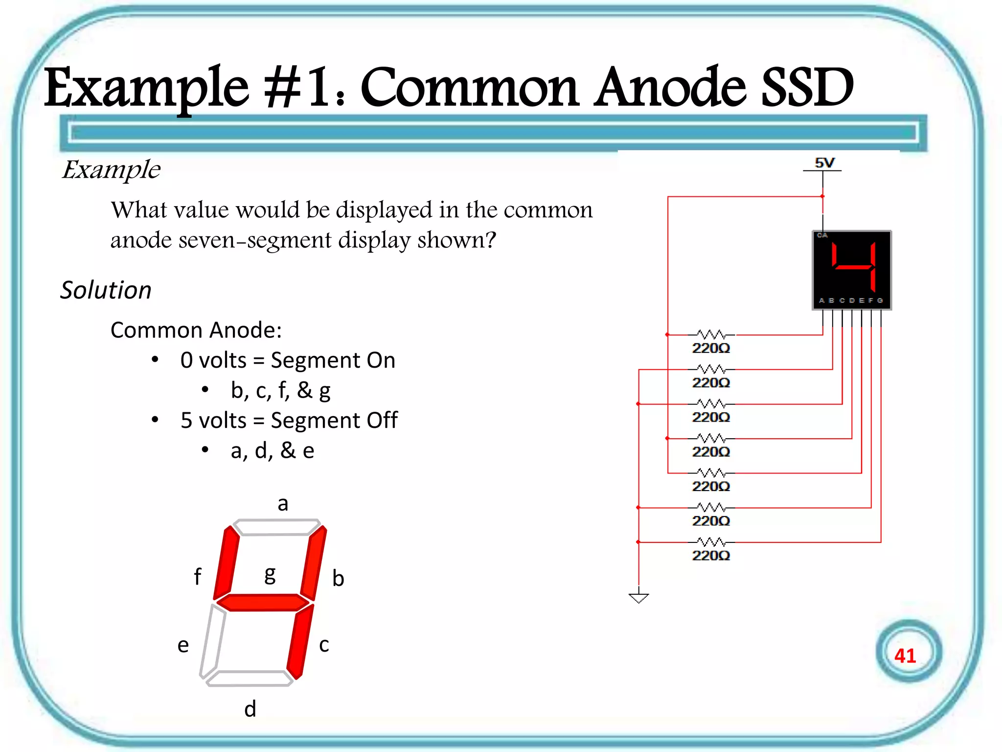
1
Outline
• Introduction (analog and digital displays)
• Types of displays
a. Cathode ray tube CRT
b. Liquid crystal display LCD
c. Light emitting diode display LED
e. Plasma display PD
• Applications of displays in measurement
2
Displays
3
Introduction
• The display system is the final link between
the measuring process and the user.
• Display devices are used in instrumentation
systems to provide instantaneous but non-
permanent communication of information
between a process or system and a human
observer.
• Data can be presented to the observer in
either an analog or a digital form
4
Continue
• In measurement there are two types of
Displays–analogue and digital.
• Analogue displays use a needle and calibrated
scale to indicate values.
• Analogue displays have a pointer which moves
over a graduated scale. They can be difficult to
read because of the need to work out the value
of the smallest scale division.
5
Continue
• For example the scale in the picture has 10
small divisions between 0 and 1 so each small
division represents 0.1. The reading is
therefore 1.25V (the pointer is estimated to be
half way between 1.2 and 1.3)
• The analogue meter can show any value
between 1.2 and 1.3 but we are unable to
read the scale more precisely than about half
a division.
6
Continue
• Digital displays show the measured value as
digits and they are more accurate than
analogue.
• They are easier to use because they give
specific value.
• Digital displays are often capable of displaying
smaller values in easy understandable way.
7
Types of displays
• Generally there are different types of displays
but the most commonly used are:
1.Cathode ray tube (CRT)
2.LED displays
3. Liquid crystal displays(LCD)
4.Plasma displays (PD)
8
Cathode ray tube
• The Cathode Ray Tube or Braun’s Tube was
invented by the German physicist Karl
Ferdinand Braun in 1897.
• Today its used in computer monitors, TV sets and
oscilloscope tubes.
• CRTs have advanced employing many different
techniques to increase image precision and
quality
• Today's CRT displays are much more advanced
than those of a decade ago, they are much
simpler than other display technologies.
9
Main components of CRT
• The CRT consists of three main components:
the electron gun, the electron beam deflector,
and the screen and phosphors
10
Electron gun
• The electron gun fires electrons.
• A strong electric field between cathode and anode
accelerates the electrons, before they leave the
electron gun through a small hole in the anode
• The electron gun consists of two main components, the
cathode and the electron beam focuser
• These two parts work together to fire an electron and
help determine where it will go
11
The Electron Beam Deflector
• The electron deflector is positioned at the base
of the vacuum tube and controls what part of
the screen the electron strikes.
• The electron beam deflector, like the focuser,
can rely on either an electromagnetic or
electrostatic mechanism
12
Continue
• The electrostatic mechanism changes the path
of the electron rather than focus it.
• Most television and computer displays use an
electromagnetic coil to control the path of the
electron
Electrostaticelectromagnetic
13
Continue
• The deflector determines the path of the
electron
• There are really two deflectors, one that
controls the position in the x, or horizontal
direction and one in the y, or vertical direction
• The electromagnetic force causes the electron
to move towards either the left or the right in
the case of the horizontal deflector.
14
Continue
• The deflector uses the force to change the
path of the electron to determine what part of
the screen the electron hits, but not which
phosphor.
15
The Screen
• The screen, which is at the front of the CRT, is
what actually displays the images.
• In color CRTs, the screen contains light-
emitting phosphors with three different
colors.
• When the electron fired from the gun strikes
the screen and hits an atom in the phosphor,
it transfers its energy to an electron in the
phosphor 16
Advantages of CRT
• Wide viewing angle
• Very simple implementation
• High resolution technology
• Excellent color fidelity
• Long life and reliability
17
Disadvantages of CRT
• High power consumption
• So Big and Bulky
• Needs cooling system
• Interference
• Less bright than CRT
18
LCD (Liquid Crystal Displays)
• The most output device Like a TV mobiles &
computer makes (display) .
• Most computers use a (LCD) , light-emitting
diode (LED), and gas plasma or other image
projection technology.
• Monitors using LCD technologies are
beginning to replace CRT
19
LCD History
• LCD were first discovered in 1888 by
Austrian botanist Friedrich Reinitzer.
• Liquid Crystals will play an important role in
modern technology .
• RCA made the first experimental LCD in
(1968).
• Manufacturers have been developing creative
variations and improvements on LCDs.
20
THE Main Categories of LDC
• The passive matrix of LCD
• The active matrix of LCD
21
THE Main Categories of LDC
• The Passive Matrix LCD
• Relies on Transistors for each Row and each
Column of pixels, the color displayed by a
pixel is determined by the electricity coming
from the transistors at the end of the row and
the top of the column .
• The most passive matrix LCD technology
screens now use dual-scan LCD Technology,
which scans the pixels twice as often.
22
THE active matrix of LCD
• Technology Assigns A Transistor to each
pixel, and each pixel is turned on and off
individually.
• Active matrix screens have a wider viewing
angle than passive matrix screens.
• Active matrix displays use Thin-Film
Transistor(TFT) Technology which employs as
many as four Transistors per pixel.
23
LCD Classifications of Color
• Monochrome
• Gray-Scale
• Color
24
LCD Classifications of Color
• Monochrome: Display only one color(such
as green, amber, or white) against a
contrasting back-ground , which is usually
black .
• These are displays used for text only displays
where the user does not need to see color
graphics.
25
LCD Classifications of Color
• Gray-Scale: A special type of monochrome
display varying intensities of gray(from a very
light gray to black) against a white or off-
chrome display.
• Gray scale flat-panel display are used in low –
end portable system-especially handheld
computers.
26
LCD Classifications of Color
• Color: Can display any where from 16 color
to over 16 million color and different colors.
Sometimes called RGB(Red , Green, Blue)
monitors .
• Today, most new display can be set to work in
monochrome or grayscale
27
Advantages of LCDs
• Physical Size
• Compact and Lightweight
• Space saving
• Can be mounted on a wall or panel
• Until recently, was only used on notebook
computers and other portable devices
28
Advantages of LCDs
• Less Power Consumption and Radiation
Emission
• LCD consumes fewer watts than a CRT. LCD
will use an average 30 watts compared to 120
watts for the CRT.
• Can reduce electric bill by 40-85%.
• Doest not emit Radiation
• Not subject to Electromagnetic Interference
29
Advantages of LCDs
• Viewing
– Cause less eyestrain
– Does not flicker or glare
• Color
– Most are capable of displaying unlimited colors.
• Resolution
– Multiple video Resolutions.
30
Disadvantages of LCDs
• It has Narrow viewing angle
• Do not Refresh the pixels very QUICKLY
• LCD Display is that their images can be
difficult To see in bright light.
31
Light-Emitting Diode Displays
• Light-emitting diode (LED) displays involve single-
crystal phosphor materials.
• LED displays are highly versatile and well suited to a
variety of measurement applications.
• Advantages of LED displays include high reliability
and graceful degrades; individual LED elements can
fail without affecting overall display performance.
32
Continue
• LEDs are rugged, for operation in harsh
environments, and they are more tolerant of
temperature extremes than other technologies.
• LEDs demonstrate better viewing angles than
LCDs, and excellent brightness for visibility in
sunlight.
33
LED Display Performance
• LED devices have excellent brightness, but because
display brightness is also a function of the filter or
magnification lenses used over the LED elements.
• Device luminance is not, by itself, a reliable measure
of overall system performance.
• LED displays also show very good luminance contrast.
34
Seven Segment Displays
• A seven-segment display can be used to display
the decimal numbers 0-9 and some alpha
characters.
• A common anode seven-segment display works.
• A common cathode seven-segment display works.
• To select the resistor value for a seven-segment
display.
35
Segment Identification
• A Seven-Segment Display (SSD) is simply a figure eight
grouping of LEDs {some include a decimal point (DP)}.
• Each Segment is labeled (a) thru (g).
• SSDs are available in two configurations
– Common Cathode (all LED cathodes are connected)
– Common Anode (all LED anodes are connected)
a
b
c
d
e
g
dp
f
36
SSD Display Possibilities
Decimal Digits 0-9
Simple Messages
Select Alpha Characters
37
Basic LED Operations
• To understand how a seven-segment
display works, we must review how an
LED works.
To Turn an LED ON . . .
• The ANODE must be at a higher
voltage potential (1.5v) than the
CATHODE.
• The amount of current flowing
through the LED will determine the
brightness of the LED.
• The amount of current is controlled by
a series resistor. (not shown)
CATHODE (‒) (+) ANODE
← Current Flow
38
LED Configuration – Anode @ 5 Volts
Switch @ 5v
• Top Circuit
• LED Off
Switch @ 0v
• Bottom Circuit
• LED On
• ANODE @ 5v
• CATHODE @ 0v (nearly)
• The 220  resistor controls the
current.
• A larger resistor . . . less current .
. . dimmer LED
• A smaller resistor . . . more
current . . . brighter LED
Common Anode
Configuration
(5v=Off / 0v=On)
39
Example #1: Common Anode SSD
Example
What value would be displayed in the common
anode seven-segment display shown?
40
Example #1: Common Anode SSD
Example
What value would be displayed in the common
anode seven-segment display shown?
Solution
Common Anode:
• 0 volts = Segment On
• b, c, f, & g
• 5 volts = Segment Off
• a, d, & e
a
b
c
d
e
gf
41
LED Configuration – Cathode @ Ground
Switch @ 5v
• Top Circuit
• LED On
• ANODE @ 5v (nearly)
• CATHODE @ 0v
• The 220  resistor controls the
current.
• A larger resistor . . . less current . . .
dimmer LED
• A smaller resistor . . . more current . .
. brighter LED
Switch @ 0v
• Bottom Circuit
• LED Off
Common Cathode
SSD Configuration
(5v=On / 0v=Off)
42
Example #2: Common Cathode SSD
Example
What value would be displayed in the common
cathode seven-segment display shown?
43
Example #2: Common Cathode SSD
Example
What value would be displayed in the common
cathode seven-segment display shown?
Solution
Common Cathode:
• 5 volts = Segment On
• a, b, d, e, & g
• 0 volts = Segment Off
• c & f
a
b
c
d
e
gf
44
Resistor Values for SSD
• The resistor value determines the amount of current that is flowing
through the LED in the SSD.
• This is why they are sometimes called current limiting resistors.
• The amount of current determines how luminous the LED will be.
• If the resistor is too large, the current will be too small and the LED
will not be visible.
• If the resistor is too small, the current will be too large and the LED
will be damaged.
• So, how do you select the correct value? You must read the data
sheet for the SSD that you are using.
45
Merits of LED displays
• Energy efficient - LED’s are now capable of
outputting 135 lumens/watt
• Long Lifetime - 50,000 hours or more if properly
engineered
• Not affected by cold temperatures - LED’s “like”
low temperatures and will startup even in
subzero weather
•
Controllable - LED’s can be controlled for
brightness and color 46
Disadvantage of LED
• LEDs are currently more expensive.
• LED performance largely depends on
correctly engineering the fixture to manage
the heat generated by the LED, which causes
deterioration of the LED chip itself.
• LEDs must be supplied with the correct
voltage and current at a constant flow. This
requires some electronics expertise to design
the electronic drivers.
47
Plasma display
• Plasma display panel is a type of flat panel display
common to large TV displays 30 inches(76 cm) or
larger.
• They are called ‘’plasma’’ displays because the
technology utilizes small cells containing
electrically charged ionized gases or what are in
essence chambers more commonly known as
fluorescent lamps .
• The plasma flat panel display. These televisions have
wide screens, comparable to the largest CRT sets, but
they are only about 6 inches (15 cm) thick.
48
Plasma display
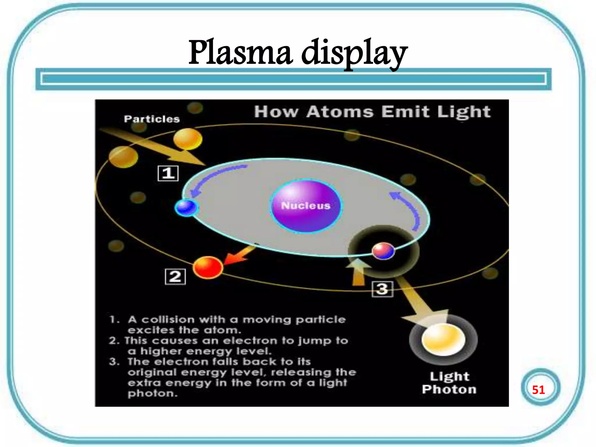
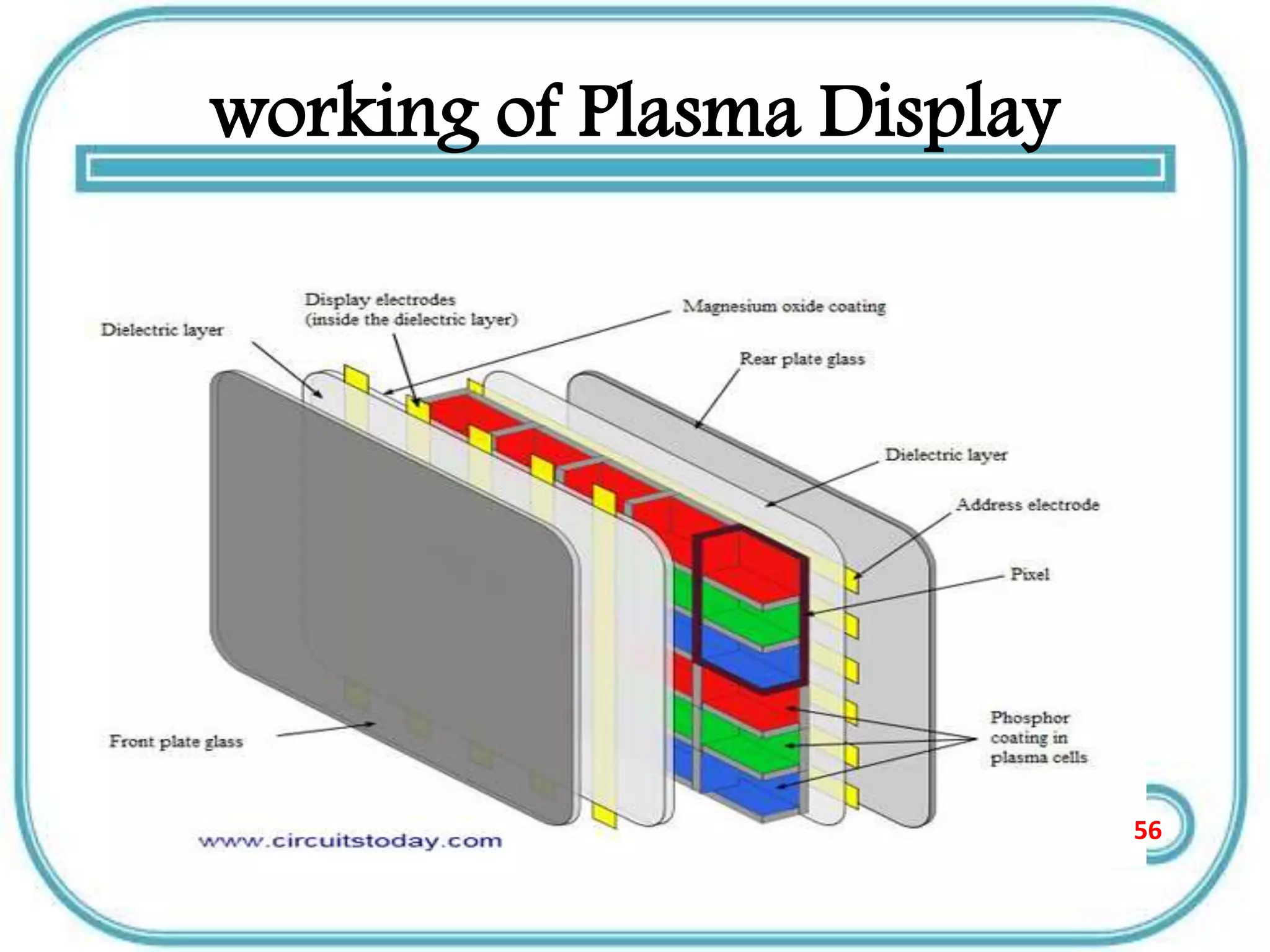
• Plasma is referred to be the main element of a
fluorescent light. It is actually a gas including
ions and electrons.
• Under normal conditions, the gas has only
uncharged particles. That is, the number o f
positive charged particles [protons] will be
equal to the number of negative charged
particles [electrons].
• This gives the gas a balanced position.
49
Plasma display
• Suppose you apply a voltage onto the gas, the number
of electrons increases and causes an unbalance.
• These free electrons hit the atoms, knocking loose
other electrons.
• Thus, with the missing electron, the component gets a
more positive charge and so becomes an ion.
• In plasma, photons of energy are released, if an
electrical current is allowed to pass through it. Both
the electrons and ions get attracted to each other
causing inter collision.
• This collision causes the energy to be produced. Take a
look at the figure illustrated below
50
Plasma display
51
Plasma display
• The basic idea of a plasma display is to
illuminate tiny, collared fluorescent lights to
form an image.
• Each pixel is made up of three fluorescent
lights -- a red light, a green light and a blue
light. Just like a CRT television, the plasma
display varies the intensities of the different
lights to produce a full range of colors.
52
working of Plasma Display
• Two plates of glass are taken between which
millions of tiny cells containing gases like
xenon and neon are filled.
• Electrodes are also placed inside the glass
plates in such a way that they are positioned in
front and behind each cell.
53
working of Plasma Display
• As told earlier when a voltage is applied, the
electrodes get charged and cause the
ionization of the gas resulting in plasma.
• This also includes the collision between the
ions and electrons resulting in the emission of
photon light.
54
working of Plasma Display
• When the photon light is emitted they are
ultraviolet in nature.
• These UV rays react with phosphor to give a
coloured light
• Take a look at the diagram given below.
55
working of Plasma Display
56
Advantages of Plasma display
• The slimmest of all displays
• Weighs less and is less bulky than CTR’s.
• Higher viewing angles compared to other
displays [178 degrees].
• Can be placed even on walls.
• Has a life span of about 100,000 hours.
57
Disadvantages of plasma display
• Cost is much higher compared to other
displays.
• Energy consumption is more.
• Produces glares due to reflection.
• These displays are not available in smaller
sizes than 32 inches..
• Cannot be used in high altitudes. The pressure
difference between the gas and the air may
cause a temporary damage or a buzzing noise.58
Applications of displays in
measurement
59
Voltmeters- analogue and digital
• Voltmeters measure voltage or
voltage drop in a circuit.
• Lack of voltage at a given point
may indicate an open circuit or
ground.
• Low or high voltage drop may
indicate a high resistance
problem like a poor connection
60
Voltmeters- analogue and digital
• Digital voltmeter has a fixed
impedance which does not
change from scale to
scale…..10M ohms or more
• Impedance is the biggest
difference between analog
and digital voltmeter.
61
AMMETERS-ANALOG AND DIGITAL
• There is not great difference between analogue and
digital ammeters.
• Digital meter are often capable of measuring smaller
currents, all the way down to micro amps.
• They are easier to use because they give specific value.
• Most digital ammeters are combined with a voltmeter.
62
oscilloscope
• Electronic test instrument that allows
observation of constantly varying
signal voltages, usually as a two-dimensional
graph
• Oscilloscopes are used to observe the change
of an electrical signal over time, such that
voltage and time describe a shape
• This shape is commonly referred to as
a waveform, and makes it easy to view
voltage changes.
• Oscilloscopes are used in the sciences,
medicine, engineering, and
telecommunications industry.
63
References ….
• Instrumentation reference book by Walt
Boyes
• Instrumentation Engineers HANDBOOK by
RCC
• Measurement & instrumentation principles by Alan
S. Morris
64
END
Any questions ????
65

analog and digital displays

  • 1.
  • 2.
    Outline • Introduction (analogand digital displays) • Types of displays a. Cathode ray tube CRT b. Liquid crystal display LCD c. Light emitting diode display LED e. Plasma display PD • Applications of displays in measurement 2
  • 3.
  • 4.
    Introduction • The displaysystem is the final link between the measuring process and the user. • Display devices are used in instrumentation systems to provide instantaneous but non- permanent communication of information between a process or system and a human observer. • Data can be presented to the observer in either an analog or a digital form 4
  • 5.
    Continue • In measurementthere are two types of Displays–analogue and digital. • Analogue displays use a needle and calibrated scale to indicate values. • Analogue displays have a pointer which moves over a graduated scale. They can be difficult to read because of the need to work out the value of the smallest scale division. 5
  • 6.
    Continue • For examplethe scale in the picture has 10 small divisions between 0 and 1 so each small division represents 0.1. The reading is therefore 1.25V (the pointer is estimated to be half way between 1.2 and 1.3) • The analogue meter can show any value between 1.2 and 1.3 but we are unable to read the scale more precisely than about half a division. 6
  • 7.
    Continue • Digital displaysshow the measured value as digits and they are more accurate than analogue. • They are easier to use because they give specific value. • Digital displays are often capable of displaying smaller values in easy understandable way. 7
  • 8.
    Types of displays •Generally there are different types of displays but the most commonly used are: 1.Cathode ray tube (CRT) 2.LED displays 3. Liquid crystal displays(LCD) 4.Plasma displays (PD) 8
  • 9.
    Cathode ray tube •The Cathode Ray Tube or Braun’s Tube was invented by the German physicist Karl Ferdinand Braun in 1897. • Today its used in computer monitors, TV sets and oscilloscope tubes. • CRTs have advanced employing many different techniques to increase image precision and quality • Today's CRT displays are much more advanced than those of a decade ago, they are much simpler than other display technologies. 9
  • 10.
    Main components ofCRT • The CRT consists of three main components: the electron gun, the electron beam deflector, and the screen and phosphors 10
  • 11.
    Electron gun • Theelectron gun fires electrons. • A strong electric field between cathode and anode accelerates the electrons, before they leave the electron gun through a small hole in the anode • The electron gun consists of two main components, the cathode and the electron beam focuser • These two parts work together to fire an electron and help determine where it will go 11
  • 12.
    The Electron BeamDeflector • The electron deflector is positioned at the base of the vacuum tube and controls what part of the screen the electron strikes. • The electron beam deflector, like the focuser, can rely on either an electromagnetic or electrostatic mechanism 12
  • 13.
    Continue • The electrostaticmechanism changes the path of the electron rather than focus it. • Most television and computer displays use an electromagnetic coil to control the path of the electron Electrostaticelectromagnetic 13
  • 14.
    Continue • The deflectordetermines the path of the electron • There are really two deflectors, one that controls the position in the x, or horizontal direction and one in the y, or vertical direction • The electromagnetic force causes the electron to move towards either the left or the right in the case of the horizontal deflector. 14
  • 15.
    Continue • The deflectoruses the force to change the path of the electron to determine what part of the screen the electron hits, but not which phosphor. 15
  • 16.
    The Screen • Thescreen, which is at the front of the CRT, is what actually displays the images. • In color CRTs, the screen contains light- emitting phosphors with three different colors. • When the electron fired from the gun strikes the screen and hits an atom in the phosphor, it transfers its energy to an electron in the phosphor 16
  • 17.
    Advantages of CRT •Wide viewing angle • Very simple implementation • High resolution technology • Excellent color fidelity • Long life and reliability 17
  • 18.
    Disadvantages of CRT •High power consumption • So Big and Bulky • Needs cooling system • Interference • Less bright than CRT 18
  • 19.
    LCD (Liquid CrystalDisplays) • The most output device Like a TV mobiles & computer makes (display) . • Most computers use a (LCD) , light-emitting diode (LED), and gas plasma or other image projection technology. • Monitors using LCD technologies are beginning to replace CRT 19
  • 20.
    LCD History • LCDwere first discovered in 1888 by Austrian botanist Friedrich Reinitzer. • Liquid Crystals will play an important role in modern technology . • RCA made the first experimental LCD in (1968). • Manufacturers have been developing creative variations and improvements on LCDs. 20
  • 21.
    THE Main Categoriesof LDC • The passive matrix of LCD • The active matrix of LCD 21
  • 22.
    THE Main Categoriesof LDC • The Passive Matrix LCD • Relies on Transistors for each Row and each Column of pixels, the color displayed by a pixel is determined by the electricity coming from the transistors at the end of the row and the top of the column . • The most passive matrix LCD technology screens now use dual-scan LCD Technology, which scans the pixels twice as often. 22
  • 23.
    THE active matrixof LCD • Technology Assigns A Transistor to each pixel, and each pixel is turned on and off individually. • Active matrix screens have a wider viewing angle than passive matrix screens. • Active matrix displays use Thin-Film Transistor(TFT) Technology which employs as many as four Transistors per pixel. 23
  • 24.
    LCD Classifications ofColor • Monochrome • Gray-Scale • Color 24
  • 25.
    LCD Classifications ofColor • Monochrome: Display only one color(such as green, amber, or white) against a contrasting back-ground , which is usually black . • These are displays used for text only displays where the user does not need to see color graphics. 25
  • 26.
    LCD Classifications ofColor • Gray-Scale: A special type of monochrome display varying intensities of gray(from a very light gray to black) against a white or off- chrome display. • Gray scale flat-panel display are used in low – end portable system-especially handheld computers. 26
  • 27.
    LCD Classifications ofColor • Color: Can display any where from 16 color to over 16 million color and different colors. Sometimes called RGB(Red , Green, Blue) monitors . • Today, most new display can be set to work in monochrome or grayscale 27
  • 28.
    Advantages of LCDs •Physical Size • Compact and Lightweight • Space saving • Can be mounted on a wall or panel • Until recently, was only used on notebook computers and other portable devices 28
  • 29.
    Advantages of LCDs •Less Power Consumption and Radiation Emission • LCD consumes fewer watts than a CRT. LCD will use an average 30 watts compared to 120 watts for the CRT. • Can reduce electric bill by 40-85%. • Doest not emit Radiation • Not subject to Electromagnetic Interference 29
  • 30.
    Advantages of LCDs •Viewing – Cause less eyestrain – Does not flicker or glare • Color – Most are capable of displaying unlimited colors. • Resolution – Multiple video Resolutions. 30
  • 31.
    Disadvantages of LCDs •It has Narrow viewing angle • Do not Refresh the pixels very QUICKLY • LCD Display is that their images can be difficult To see in bright light. 31
  • 32.
    Light-Emitting Diode Displays •Light-emitting diode (LED) displays involve single- crystal phosphor materials. • LED displays are highly versatile and well suited to a variety of measurement applications. • Advantages of LED displays include high reliability and graceful degrades; individual LED elements can fail without affecting overall display performance. 32
  • 33.
    Continue • LEDs arerugged, for operation in harsh environments, and they are more tolerant of temperature extremes than other technologies. • LEDs demonstrate better viewing angles than LCDs, and excellent brightness for visibility in sunlight. 33
  • 34.
    LED Display Performance •LED devices have excellent brightness, but because display brightness is also a function of the filter or magnification lenses used over the LED elements. • Device luminance is not, by itself, a reliable measure of overall system performance. • LED displays also show very good luminance contrast. 34
  • 35.
    Seven Segment Displays •A seven-segment display can be used to display the decimal numbers 0-9 and some alpha characters. • A common anode seven-segment display works. • A common cathode seven-segment display works. • To select the resistor value for a seven-segment display. 35
  • 36.
    Segment Identification • ASeven-Segment Display (SSD) is simply a figure eight grouping of LEDs {some include a decimal point (DP)}. • Each Segment is labeled (a) thru (g). • SSDs are available in two configurations – Common Cathode (all LED cathodes are connected) – Common Anode (all LED anodes are connected) a b c d e g dp f 36
  • 37.
    SSD Display Possibilities DecimalDigits 0-9 Simple Messages Select Alpha Characters 37
  • 38.
    Basic LED Operations •To understand how a seven-segment display works, we must review how an LED works. To Turn an LED ON . . . • The ANODE must be at a higher voltage potential (1.5v) than the CATHODE. • The amount of current flowing through the LED will determine the brightness of the LED. • The amount of current is controlled by a series resistor. (not shown) CATHODE (‒) (+) ANODE ← Current Flow 38
  • 39.
    LED Configuration –Anode @ 5 Volts Switch @ 5v • Top Circuit • LED Off Switch @ 0v • Bottom Circuit • LED On • ANODE @ 5v • CATHODE @ 0v (nearly) • The 220  resistor controls the current. • A larger resistor . . . less current . . . dimmer LED • A smaller resistor . . . more current . . . brighter LED Common Anode Configuration (5v=Off / 0v=On) 39
  • 40.
    Example #1: CommonAnode SSD Example What value would be displayed in the common anode seven-segment display shown? 40
  • 41.
    Example #1: CommonAnode SSD Example What value would be displayed in the common anode seven-segment display shown? Solution Common Anode: • 0 volts = Segment On • b, c, f, & g • 5 volts = Segment Off • a, d, & e a b c d e gf 41
  • 42.
    LED Configuration –Cathode @ Ground Switch @ 5v • Top Circuit • LED On • ANODE @ 5v (nearly) • CATHODE @ 0v • The 220  resistor controls the current. • A larger resistor . . . less current . . . dimmer LED • A smaller resistor . . . more current . . . brighter LED Switch @ 0v • Bottom Circuit • LED Off Common Cathode SSD Configuration (5v=On / 0v=Off) 42
  • 43.
    Example #2: CommonCathode SSD Example What value would be displayed in the common cathode seven-segment display shown? 43
  • 44.
    Example #2: CommonCathode SSD Example What value would be displayed in the common cathode seven-segment display shown? Solution Common Cathode: • 5 volts = Segment On • a, b, d, e, & g • 0 volts = Segment Off • c & f a b c d e gf 44
  • 45.
    Resistor Values forSSD • The resistor value determines the amount of current that is flowing through the LED in the SSD. • This is why they are sometimes called current limiting resistors. • The amount of current determines how luminous the LED will be. • If the resistor is too large, the current will be too small and the LED will not be visible. • If the resistor is too small, the current will be too large and the LED will be damaged. • So, how do you select the correct value? You must read the data sheet for the SSD that you are using. 45
  • 46.
    Merits of LEDdisplays • Energy efficient - LED’s are now capable of outputting 135 lumens/watt • Long Lifetime - 50,000 hours or more if properly engineered • Not affected by cold temperatures - LED’s “like” low temperatures and will startup even in subzero weather • Controllable - LED’s can be controlled for brightness and color 46
  • 47.
    Disadvantage of LED •LEDs are currently more expensive. • LED performance largely depends on correctly engineering the fixture to manage the heat generated by the LED, which causes deterioration of the LED chip itself. • LEDs must be supplied with the correct voltage and current at a constant flow. This requires some electronics expertise to design the electronic drivers. 47
  • 48.
    Plasma display • Plasmadisplay panel is a type of flat panel display common to large TV displays 30 inches(76 cm) or larger. • They are called ‘’plasma’’ displays because the technology utilizes small cells containing electrically charged ionized gases or what are in essence chambers more commonly known as fluorescent lamps . • The plasma flat panel display. These televisions have wide screens, comparable to the largest CRT sets, but they are only about 6 inches (15 cm) thick. 48
  • 49.
    Plasma display • Plasmais referred to be the main element of a fluorescent light. It is actually a gas including ions and electrons. • Under normal conditions, the gas has only uncharged particles. That is, the number o f positive charged particles [protons] will be equal to the number of negative charged particles [electrons]. • This gives the gas a balanced position. 49
  • 50.
    Plasma display • Supposeyou apply a voltage onto the gas, the number of electrons increases and causes an unbalance. • These free electrons hit the atoms, knocking loose other electrons. • Thus, with the missing electron, the component gets a more positive charge and so becomes an ion. • In plasma, photons of energy are released, if an electrical current is allowed to pass through it. Both the electrons and ions get attracted to each other causing inter collision. • This collision causes the energy to be produced. Take a look at the figure illustrated below 50
  • 51.
  • 52.
    Plasma display • Thebasic idea of a plasma display is to illuminate tiny, collared fluorescent lights to form an image. • Each pixel is made up of three fluorescent lights -- a red light, a green light and a blue light. Just like a CRT television, the plasma display varies the intensities of the different lights to produce a full range of colors. 52
  • 53.
    working of PlasmaDisplay • Two plates of glass are taken between which millions of tiny cells containing gases like xenon and neon are filled. • Electrodes are also placed inside the glass plates in such a way that they are positioned in front and behind each cell. 53
  • 54.
    working of PlasmaDisplay • As told earlier when a voltage is applied, the electrodes get charged and cause the ionization of the gas resulting in plasma. • This also includes the collision between the ions and electrons resulting in the emission of photon light. 54
  • 55.
    working of PlasmaDisplay • When the photon light is emitted they are ultraviolet in nature. • These UV rays react with phosphor to give a coloured light • Take a look at the diagram given below. 55
  • 56.
  • 57.
    Advantages of Plasmadisplay • The slimmest of all displays • Weighs less and is less bulky than CTR’s. • Higher viewing angles compared to other displays [178 degrees]. • Can be placed even on walls. • Has a life span of about 100,000 hours. 57
  • 58.
    Disadvantages of plasmadisplay • Cost is much higher compared to other displays. • Energy consumption is more. • Produces glares due to reflection. • These displays are not available in smaller sizes than 32 inches.. • Cannot be used in high altitudes. The pressure difference between the gas and the air may cause a temporary damage or a buzzing noise.58
  • 59.
    Applications of displaysin measurement 59
  • 60.
    Voltmeters- analogue anddigital • Voltmeters measure voltage or voltage drop in a circuit. • Lack of voltage at a given point may indicate an open circuit or ground. • Low or high voltage drop may indicate a high resistance problem like a poor connection 60
  • 61.
    Voltmeters- analogue anddigital • Digital voltmeter has a fixed impedance which does not change from scale to scale…..10M ohms or more • Impedance is the biggest difference between analog and digital voltmeter. 61
  • 62.
    AMMETERS-ANALOG AND DIGITAL •There is not great difference between analogue and digital ammeters. • Digital meter are often capable of measuring smaller currents, all the way down to micro amps. • They are easier to use because they give specific value. • Most digital ammeters are combined with a voltmeter. 62
  • 63.
    oscilloscope • Electronic testinstrument that allows observation of constantly varying signal voltages, usually as a two-dimensional graph • Oscilloscopes are used to observe the change of an electrical signal over time, such that voltage and time describe a shape • This shape is commonly referred to as a waveform, and makes it easy to view voltage changes. • Oscilloscopes are used in the sciences, medicine, engineering, and telecommunications industry. 63
  • 64.
    References …. • Instrumentationreference book by Walt Boyes • Instrumentation Engineers HANDBOOK by RCC • Measurement & instrumentation principles by Alan S. Morris 64
  • 65.