SlideShare a Scribd company logo
1 of 79
Download to read offline
55
© 2012 Cengage Learning. All Rights Reserved. May not be scanned, copied or duplicated, or posted to a publicly accessible website, in whole or in part.
CHAPTER 2: MODELING OF SDOF
SYSTEMS
Short Answer Problems
2.1 True: the differential equations are the same because the resultant of gravity and the
static spring force is zero for the case of the hanging mass-spring-viscous damper system.
2.2 False: The differential equation governing the motion of a SDOF linear system is
second order.
2.3 False: Springs in parallel have an equivalent stiffness that is the sum of the individual
stiffnesses of these springs.
2.4 False: The equivalent stiffness of a uniform simply supported beam at its middle is
.
2.5 True: Viscous damping is often added to a system to add a linear term in the governing
differential equation.
2.6 False: When the equivalent systems method is used to derive the differential equation
for a system with an angular coordinate used as the generalized coordinate the kinetic
energy is used to derive the equivalent moment of inertia of the system.
2.7 True: The equivalent systems method applied only to linear systems.
2.8 False: The inertia effects of simply supported beam can be approximated by calculating
the kinetic energy of the beam in terms of the velocity of the generalized coordinate and
placing a particle of appropriate mass at the location whose displacement the generalized
coordinate represents.
2.9 False: The static deflection of the spring in the system of Fig. SP2.9 is .
 
Mechanical Vibrations Theory and Applications 1st Edition Kelly Solutions Manual
Full Download: http://alibabadownload.com/product/mechanical-vibrations-theory-and-applications-1st-edition-kelly-solutions-ma
This sample only, Download all chapters at: alibabadownload.com
Chapter 2: Modeling of SDOF Systems
 
56
© 2012 Cengage Learning. All Rights Reserved. May not be scanned, copied or duplicated, or posted to a publicly accessible website, in whole or in part.
2.10 False: The springs in the system of Fig. SP2.10 are in parallel (the
springs have the same displacement, x, and the resultant force on the FBD of
the block is the sum of the spring forces).
2.11 True: A shaft is an elastic member in which an angular displacement
occurs when acted on by a torque. The angular displacement has a value of
/ .
2.12 True: The equivalent viscous damping coefficient is calculated by
comparing the energy dissipation in the combination of viscous dampers to
that of an equivalent viscous damper.
2.13 False: The added mass of a fluid entrained by a vibrating system is determined by
calculating the kinetic energy developed in the fluid.
2.14 False: If it is desired to calculate the reactions at the support
of Fig SP2.14 the effects of the static spring force and gravity
cancel and do need to be included on the FBD or in summing
forces on the FBD (the cancelling of static spring forces with
gravity only applies to the derivation of the differential equation).
2.15 False: Gravity does not cancel with the static spring force in the system of Figure
SP2.15 and hence the potential energy of both is included in potential
energy calculations. (Assuming small the potential energy in the spring
is . The potential energy due to gravity assuming the datum is
the pin support is sin ).
2.16 The small angle assumption is used to linearize nonlinear systems a
priori. If the angular displacement is small it is assumed that sin
, cos 1, tan in derivation of the differential equation.
2.17 FBD's are drawn at an arbitrary instant for derivation of differential
equations.
2.18 A quadratic form is form of kinetic energy equal to when used to apply the
equivalent systems method to derive a differential equation. The potential energy has a
quadratic form of .
2.19 The inertia effects of the spring in a mass-spring-viscous damper system can be
approximated by adding a particle of 1/3 the mass of the spring to the point on the system
where the spring is attached.
2.20 Each spring in a parallel combination has the same displacement.
2.21 The equivalent stiffness of a combination of springs is calculated by requiring the
total potential energy of the combination when written in terms of the displacement of the
Chapter 2: Modeling of SDOF Systems 
57
© 2012 Cengage Learning. All Rights Reserved. May not be scanned, copied or duplicated, or posted to a publicly accessible website, in whole or in part.
particle where the equivalent spring is to be attached is equal to the potential energy of a
spring of equivalent stiffness placed at that location.
2.22 The FBD is shown at an arbitrary instant.
2.23 At an arbitrary instant the upper bar has rotated through an angle , measured positive
clockwise. The lower bar has an angular displacement , measure counterclockwise. The
displacements of the particles must be the same where the rigid bar is attached,
or . The FBDs are shown at an arbitrary instant.


2.24 The equivalent systems method is used to derive the differential equation for linear
SDOF systems. It can be used to model a linear SDOF system with an equivalent mass-
spring-viscous damper model. Using a linear displacement as the generalized coordinate
the equivalent mass, the equivalent stiffness, the equivalent damping viscous damping
coefficient and the equivalent force are determined using the kinetic energy, potential
energy, energy dissipated by viscous dampers and the work done by non-conservative
forces.
2.25 Static spring forces not drawn on the FBD of external forces when they cancel with a
source of potential energy for a linear system and the generalized coordinate is measured
from the system's equilibrium position.
2.26 No, the equivalent systems method cannot be used for a nonlinear system.
Chapter 2: Modeling of SDOF Systems
 
58
© 2012 Cengage Learning. All Rights Reserved. May not be scanned, copied or duplicated, or posted to a publicly accessible website, in whole or in part.
2.27 Given: Springs of individual stiffness’s and placed in series. The equivalent
stiffness of the combination is .
2.28 Given: System of Figure SP2.28. The diagrams showing the reduction to a single
spring of equivalent stiffness of .
2.29 Given: System of Figure 2.29. The aluminum shaft is in
series with the steel shaft (angular displacements add). The
stiffness of the aluminum shaft is
.
.
2.10 10 N·m/rad . The
stiffness of the steel shaft is
.
.
1.06 10 N·m/rad. The equivalent stiffness is
/ /
6.94 10 N·m/rad.
2.30 Given: F = 300 N ∆ 1 mm. The stiffness of the element is
∆
N
.
3
10 N/m.
2.31 Given: F=300 N ∆ 1 mm. The potential energy is ∆ 3
105 N/m20.001 m2 0.15 J.
2.32 Given: F=300 N ∆ 1 mm. The potential energy is the same for a compressive force
as for a tensile force. The potential energy is
∆ 3 10 N/m 0.001 m 0.15 J.
2.33 Given: 250 N · , 2°. The potential energy developed in the spring is
250 N · 2°
°
0.153 J.
Chapter 2: Modeling of SDOF Systems 
59
© 2012 Cengage Learning. All Rights Reserved. May not be scanned, copied or duplicated, or posted to a publicly accessible website, in whole or in part.
2.34 Given: G = 80 × 10 N/m L = 2.5 m , = 10 cm, 15 cm The polar moment of
inertia is 0.15 0.1 6.38x10 m . The torsional stiffness
of the shaft is
. N/
.
2.04 10 N · m/rad.
2.35 Given: G = 40 × 10 N/m , L 1.8 m, r = 25 cm. The polar moment of inertia is
0.25 6.12 10 m . The torsional stiffness of the shaft is
. N/
.
1.36 10 N · m/rad.
2.36 Given: E = 200 × 10 N/m , L 2.3 m, rectangular cross-section 5 cm × 6 cm. The
longitudinal stiffness of the bar is
. . N/
.
2.61
10 N/m.
2.37 Given: E = 200 × 10 N/m , L = 10 , beam of rectangular cross section of width
1 and height 0.5 . The stiffness of a cantilever beam at its end is
N/ . /
= 6.25 N/m.
2.38 Given: k = 4000 N/m, m=20 kg. The static deflection of the spring is ∆
. /
N/
4.91 cm
2.39 Given: ℓ 10 cm, 2.3 g/cm, m = 150 g. The mass of the spring is ℓ
2.3 g/cm 0.1 m 0.023 kg 23 g. The added mass is
7.67 g.
2.40 Given: System of Figure SP2.40. The inertia
effects of the springs are approximated by adding a
particle of mass /3 to the center of the disk and a
particle of mass /3 to the suspended block. The
total kinetic energy of the system is
. The kinetic
energy of the block and the second spring is
The angular displacement
of the pulley is and its kinetic energy is
The displacement of the
center of the disk is . The disk rolls
Chapter 2: Modeling of SDOF Systems
 
60
© 2012 Cengage Learning. All Rights Reserved. May not be scanned, copied or duplicated, or posted to a publicly accessible website, in whole or in part.
without slipping, . The
kinetic energy of the first spring is . The total kinetic
energy of the system is .
2.41 Given: System of Figure SP2.41. The work done by
the viscous dampers as the system rotates through an
angle is 
. 
 
2.42 (a) sin 0.05 = 0.05; (b) cos 0.05 = 1; (c) 1-cos 0.05 =
0.05 /2 = 0.00125; (d) tan 0.05 = 0.05; (e) cot 0.05 = 1/tan 0.05 = 1/0.05 = 20; (f) sec
0.05 = 1/cos 0.05 = 1; (g) csc 0.05 = 1/sin 0.05 = 20
2.43 (a) sin 3° = 6 /360 = /60; (b) cos 3° = 1; (c) 1-cos 3° = ; (d) tan 3° = /60
2.44 Given: System of Figure 2.44. The kinetic
energy of the system is
2.45 (a)-(vi); (b)-(iii); (c)-(iv); (d)-(vii); (e)-(i); (f)-(iv); (g)-(v); (h)-(ii)


Chapter 2: Modeling of SDOF Systems 
61
© 2012 Cengage Learning. All Rights Reserved. May not be scanned, copied or duplicated, or posted to a publicly accessible website, in whole or in part.
Chapter Problems
2.1 Determine the equivalent stiffness
of a linear spring when a SDOF mass-
spring model is used for the system
shown in Figure P2.1 with x being the
chosen generalized coordinate.
Given: L = 2 m, E = 200 × 109
N/m2
, I = 1.15 × 10⁻⁴
m4
, m = 20 kg
Find: keq
Solution: The deflection of a pinned-pinned beam at its midspan is determined using Table
D.2 with a = L/2, Z = L/2 as
EI48
L
2LZy
3
== )/(
The equivalent stiffness is the reciprocal of the deflection,
m
N
101.38
(2m)
)m10)(1.15
m
N
1048(20
48
8
3
44
2
9
3
×=
××
=
=
−
L
EI
keq
Problem 2.1 illustrates the determination of the equivalent stiffness of a structural member.
2.2 Determine the equivalent stiffness of a linear
spring when a SDOF mass-spring model is used for
the systems shown in Figure P2.2 with x being the
chosen generalized coordinate.
Given: k, E, I, L
Find: keq
Solution: The cantilever beam behaves as a linear spring. The displacement of the end of
the upper spring and the end of the cantilever beam are the same. Thus the beam is in
parallel with the upper spring. The equivalent stiffness of the cantilever beam at its end is
Chapter 2: Modeling of SDOF Systems
 
62
© 2012 Cengage Learning. All Rights Reserved. May not be scanned, copied or duplicated, or posted to a publicly accessible website, in whole or in part.
3b
L
EI3
k =
Thus the equivalent stiffness of the beam and spring in parallel is
k
L
EI3
k 3eq1
+=
The total deflection of the system is the deflection of the beam plus the change in length of
the lower spring. Thus the lower spring is in series with the beam and upper spring. Using
the equation for a series combination of springs
3
3
3
eq
eq
L
EI3
k2
L
EI3
kk
L
EI3
k
1
k
1
1
k
1
k
1
1
k
1
+
⎟
⎠
⎞
⎜
⎝
⎛
+
=
+
+
=
+
=
Problem 2.2 illustrates (a) principles for determining parallel and series combination of
springs and (b) use of the formulas for series and parallel spring combinations.
2.3 Determine the equivalent stiffness of a
linear spring when a SDOF mass-spring
model is used for the the system shown in
Figure P2.3 with x being the chosen
generalized coordinate.
Given: Fixed-pinned beam with overhang, dimensions shown
Find: keq.
Solution: The 20 kg machine is placed at A on the beam. Using the displacement of A as
the generalized coordinate, the equivalent stiffness is the reciprocal of the displacement at
A due to a unit concentrated load at A. From Table D2, with a = 0.6m, z1 = 1.0 m, the
displacement at A due to a unit concentrated load at A is
Chapter 2: Modeling of SDOF Systems 
63
© 2012 Cengage Learning. All Rights Reserved. May not be scanned, copied or duplicated, or posted to a publicly accessible website, in whole or in part.
( ) 43
2
2
3
1 CaC
2
a
C
6
a
CazEIy +++== (1)
where
  568
z
a
1
2
1
z
a
2
3
2
3
C
3
11
1 .−=⎟⎟
⎠
⎞
⎜⎜
⎝
⎛
−++−=   (2) 
  1680
z
a
11
z
a
1
2
z
C
2
11
1
2 .=
⎥
⎥
⎦
⎤
⎢
⎢
⎣
⎡
⎟⎟
⎠
⎞
⎜⎜
⎝
⎛
−−⎟⎟
⎠
⎞
⎜⎜
⎝
⎛
−=   (3) 
  0C3 =   (4) 
  0C4 =   (5) 
Substituting eqs.(2)-(5) in eq.(l) leads to
( ) ( ) ( ) 01083
2
60
1680
6
60
53860zEIy
23
.
.
.
.
.. =+−==
Hence the equivalent stiffness is
( )
EI392
EI
010830
1
60zy
1
keq .
..
. ==
=
=
Problem 2.3 illustrates the concept of equivalent stiffness for a one degree of freedom
model of a mass attached to a beam. The equations and entries of Table D2 are used to
determine the equivalent stiffness.
2.4 Determine the equivalent stiffness of a linear
spring when a SDOF mass-spring model is used for
the system shown in Figure P2.4 with x as the chosen
generalized coordinate.
 
Given: system shown
Solution: The stiffness of the fixed-free beam is
3 3 210 10 N/m 6.1 10 m
2.5 m
2.50 10 N/m
Chapter 2: Modeling of SDOF Systems
 
64
© 2012 Cengage Learning. All Rights Reserved. May not be scanned, copied or duplicated, or posted to a publicly accessible website, in whole or in part.
The stiffness of the pinned-pinned beam is
48 48 210 10 N/m 6.1 10 m
2.5 m
3.94 10 N/m
The equivalent stiffness is given by the model shown below. The upper beam acts in series
with the upper spring (the displacements of the springs add to given the displacement of
the midspan of the simply supported beam). The lower beam acts in series with the middle
spring (their displacements add). The upper spring combination acts in parallel with the
lower beam-spring combination. Both act in parallel with the spring below the mass. The
equivalent stiffness of the upper beam and spring is
,
1
1
3.94 10
1
6 10
7.11 10 N/m
The equivalent stiffness of the lower spring and beam is
,
1
1
2.5 10
1
1 10
5.91 10 N/m
The equivalent stiffness of the combination is
7.11 10
N
m
5.91 10
N
m
8 10
N
m
2.10 10 N/m
Problem 2.4 illustrates the equivalent stiffness of a combination of springs.
2.5 Determine the equivalent stiffness of a linear
spring when a SDOF mass-spring model is used
for the system shown in Figure P2.5 with x as the
chosen generalized coordinate.
Given: system shown
Given:
Solution: The potential energy of a spring of equivalent stiffness located at the point whose
displacement is x is
1
2
The potential energy of the system, using x as a generalized coordinate, is
Chapter 2: Modeling of SDOF Systems 
65
© 2012 Cengage Learning. All Rights Reserved. May not be scanned, copied or duplicated, or posted to a publicly accessible website, in whole or in part.
1
2
3
1
2
5
3
1
2
4
1
2
196
9
Thus the equivalent stiffness is
196
9
Problem 2.5 illustrates the equivalence of two systems of springs using potential energy.
2.6 Determine the equivalent stiffness of a linear spring
when a SDOF mass-spring model is used for the system
shown in Figure P2.6 with x as the chosen generalized
coordinate.
Given: system shown
Given:
Solution: The potential energy of a spring of equivalent stiffness located at the point whose
displacement is x is
1
2
The potential energy of the system, using x as a generalized coordinate, is
1
2
1
2
2
1
2 3
1
2
10
9
Thus the equivalent stiffness is
10
9
Problem 2.6 illustrates the equivalence of two systems of springs using potential energy.
 
2.7 Determine the equivalent stiffness of a
linear spring when a SDOF mass-spring
model is used for the system shown in
Figure P2.7 with x as the chosen
generalized coordinate.
Chapter 2: Modeling of SDOF Systems
 
66
© 2012 Cengage Learning. All Rights Reserved. May not be scanned, copied or duplicated, or posted to a publicly accessible website, in whole or in part.
Given: system shown
Given:
Solution: The potential energy of a spring of equivalent stiffness located at the point whose
displacement is x is
1
2
The angular displacement of the upper bar is , measured positive clockwise. The angular
displacement of the lower bar is , measured positive counterclockwise. The particles
attached to the rigid link have the same displacement
2
3
Noting that
4
3
thus
9
8
The potential energy of the system, using x as a generalized coordinate, is
1
2
1
2
3
8
1
2
3
4
1
2
2
3
8
1
2
127
64
Thus the equivalent stiffness is
127
64
Problem 2.7 illustrates the equivalence of two systems of springs using potential energy.
2.8 Determine the equivalent stiffness of a
linear spring when a SDOF mass-spring
model is used for the system shown in Figure
P2.8 with x as the chosen generalized
coordinate.
Given: system shown
Chapter 2: Modeling of SDOF Systems 
67
© 2012 Cengage Learning. All Rights Reserved. May not be scanned, copied or duplicated, or posted to a publicly accessible website, in whole or in part.
Given:
Solution: The potential energy of a spring of equivalent stiffness located at the point whose
displacement is x is
1
2
The spring attached to the disk and around the pulley has a displacement of 3x, x from the
displacement of the mass center and 2x (assuming no slip between the disk and the
surface) from the angular rotation of the disk. The potential energy of the system, using x
as a generalized coordinate, is
1
2
3
1
2
3
1
2
12
Thus the equivalent stiffness is
12
Problem 2.8 illustrates the equivalence of two systems of springs using potential energy.
2.9 Two helical coil springs are made from a steel E 200 10 N/m bar of radius 20
mm. One spring has a coil diameter of 7 cm; the other has a coil diameter of 10 cm. The
springs have 20 turns each. The spring with the smaller coil diameter is placed inside the
spring with the larger coil diameter. What is the equivalent stiffness of the assembly?
Given: E 200 10 N/m (or 80 10 N/m , r = 20 mm, 7 cm,
10 cm, 20
Find:
Solution: The stiffness of the inner spring is
64
80 10 N/m 0.07 m
64 20 0.02
1.88 10 N/m
The stiffness of the outer spring is
64
80 10 N/m 0.10 m
64 20 0.02
7.81 10 N/m
The springs act in parallel, the displacements are the same and the force on the block is the
sum of the forces in the springs. Thus
1.88 10
N
m
7.81 10
N
m
9.69 10
N
m
Chapter 2: Modeling of SDOF Systems
 
68
© 2012 Cengage Learning. All Rights Reserved. May not be scanned, copied or duplicated, or posted to a publicly accessible website, in whole or in part.
Problem 2.9 illustrates springs acting in parallel.
2.10 A thin disk attached to the end of
an elastic beam has three uncoupled
modes of vibration. The longitudinal
motion, the transverse motion, and the
torsional oscillations are kinematically independent. Calculate the following of Figure
P2.10. (a) The longitudinal stiffness; (b) The transverse stiffness; (c) The torsional stiffness
Given: L = 65 cm, r = 10 mm, E = 200 × 109
N/m2
, G = 80 × 109
N/m2
Find: kl, kθ, and ky
Solution: The geometric properties of the beam are
( )
( )
( ) 4944
4844
2422
m107.58m0.01
44
m101.57m0.01
22
m103.14m0.01π
−
−
−
×===
×===
×===
ππ
ππ
π
rI
rJ
rA
(a) The longitudinal stiffness is
( )
m
N
109.67
m0.65
m
N
10200m103.14
7
2
924
×=
⎟
⎠
⎞
⎜
⎝
⎛
××
==
−
L
AE
kl
(b) The transverse stiffness is
( )
( ) m
N
101.72
m0.65
m107.85
m
N
102003
3 4
3
49
2
9
3
×=
×⎟
⎠
⎞
⎜
⎝
⎛
×
==
−
L
EI
ky
(c) The torsional stiffness is
( )
rad
mN
1930
m0.65
m
N
1080m101.57 2
948
⋅
=
⎟
⎠
⎞
⎜
⎝
⎛
××
==
−
L
JG
kθ
Problem 2.10 illustrates three independent modes of vibration of a cantilever beam.
Chapter 2: Modeling of SDOF Systems 
69
© 2012 Cengage Learning. All Rights Reserved. May not be scanned, copied or duplicated, or posted to a publicly accessible website, in whole or in part.
2.11 Find the equivalent stiffness of the springs in Figure
P2.11 in the x direction.
Given: springs shown
Find:
Solution: A FBD of the particle at an arbitrary instant is shown
Summing forces on the FBD in the x direction leads to
4 10 0.866 3 10 0.707 5 10 0.707 9.12 10
Hence the equivalent stiffness in the x direction is
9.12 10
N
m
Problem 2.11 illustrates the determination of an equivalent stiffness when springs act on a
particle at different angles.
2.12 A bimetallic strip used as a MEMS
sensor is shown in Figure P2.12. The strip has
a length of 20 . The width of the strip is 1
m. It has an upper layer made of steel
210 10 N/m and a lower layer
made of aluminum 80 10 N/m .
Each layer is 0.1 m thick. Determine the equivalent stiffness of the strip in the axial
direction.
Given: L = 20 m, w = 1 m, 210 10 N/m , 80 10 N/m , t = 0.1 m
Find:
Chapter 2: Modeling of SDOF Systems
 
70
© 2012 Cengage Learning. All Rights Reserved. May not be scanned, copied or duplicated, or posted to a publicly accessible website, in whole or in part.
Solution: The two layers behave as longitudinal springs in parallel. The layers have the
same displacement and the forces from the layers add. The equivalent stiffness of a
longitudinal spring is
The strips have the same area and same length. The equivalent stiffness is the sum of the
individual stiffnesses thus
210 10
N
m
80 10 N/m
1 μm 0.1 μm
20 μm
1450
N
m
Problem 2.12 illustrates equivalent stiffness of spring in series.
2.13 A gas spring consists of a piston of area A moving in a cylinder of gas. As the piston
moves, the gas expands and contracts, changing the pressure exerted on the piston. The
process occurs adiabatically (without heat transfer) so that
where p is the gas pressure, is the gas density, is the constant ratio of specific heats,
and C is a constant dependent on the initial state. Consider a spring when the initial
pressure is and the initial temperature is . At this pressure, the height of the gas
column in the cylinder is h. Let be the pressure force acting on the piston
when it has displaced a distance x into the gas from its initial height.
(a) Determine the relation between and x.
(b) Linearize the relationship of part (a) to approximate the air spring by a linear spring.
What is the equivalent stiffness of the spring?
(c) What is the required piston area for an air spring ( 1.4 to have a stiffness of 300
N·m for a pressure of 150 kPa (absolute) with h = 30 cm.
Given: , , , , (c) k=300 N/m, 150 kPa, h=0.3 m, 1.4
Find: (a) and x relation (b) k (c) A
Solution: (a) The ideal gas law is used to find the density in the initial state
The initial volume of gas in the spring is
Chapter 2: Modeling of SDOF Systems 
71
© 2012 Cengage Learning. All Rights Reserved. May not be scanned, copied or duplicated, or posted to a publicly accessible website, in whole or in part.
The total mass of the air is
When the piston has moved a distance x from its equilibrium position at an arbitrary time
Since the total mass of the gas is constant the density becomes
The initial state is defined by
At an arbitrary time
(b) The force exerted on the piston is . Thus
1
But from a binomial expansion
1 1
Thus
(c) Solving for A and substituting given values
300 N/m 0.3 m
1.4 150000 N/m
4.29 10 m
Problem 2.13 illustrates the linearized stiffness for an air spring.
Chapter 2: Modeling of SDOF Systems
 
72
© 2012 Cengage Learning. All Rights Reserved. May not be scanned, copied or duplicated, or posted to a publicly accessible website, in whole or in part.
mg =
F =
Lhr
Ldr( 1+d/h)
ρ
ρθ
wg
2.14 A wedge is floating stably on an interface
between a liquid of mass density ρ, as shown in
Figure P2.14. Let x be the displacement of the
wedge’s mass center when it is disturbed from
equilibrium. (a) What is the buoyant force
acting on the wedge? (b) What is the work done
by the buoyant force as the mass center of the
wedge moves from x1 and x2? (c) What is the
equivalent stiffness of the spring if the motion of
the mass center of the wedge is modeled by a mass attached to a linear spring?
Given: ρ, ρw, r, L, h
Find: FB, W, linear system
Solution: (a) Consider a free-body diagram of the wedge as it
floats in equilibrium on the free surface. Let d be the depth of the
wedge into the liquid. In this state the buoyant force must
balance with the gravity force
⎟
⎠
⎞
⎜
⎝
⎛
+=
=⎟
⎠
⎞
⎜
⎝
⎛
+
=−
h
d
1dh
gLhr
h
d
1Ldr
0WF
w
w
B
ρρ
ρρ
(1)
Now consider the wedge as it oscillates on the free surface. The buoyant force at an
arbitrary time is
( )
⎥
⎦
⎤
⎢
⎣
⎡
+++⎟
⎠
⎞
⎜
⎝
⎛
+=
⎟
⎠
⎞
⎜
⎝
⎛ +
++=
h
x
xx
h
d
2
h
d
1dgLr
h
xd
1rxdgLF
2
B
ρ
ρ
(b) The work done by the buoyant force as the center of mass moves between x1 and x2
is
dx
h
x
xx
h
d
2
h
d
1dgLr
dxFW
2x
x
x
x
B21
2
1
2
1
⎥
⎦
⎤
⎢
⎣
⎡
+++⎟
⎠
⎞
⎜
⎝
⎛
+
==
∫
∫→
ρ
Chapter 2: Modeling of SDOF Systems 
73
© 2012 Cengage Learning. All Rights Reserved. May not be scanned, copied or duplicated, or posted to a publicly accessible website, in whole or in part.
( ) ( ) ( ) ( )⎥
⎦
⎤
⎢
⎣
⎡
−+−+−+−⎟
⎠
⎞
⎜
⎝
⎛
+=→
3
1
3
2
2
1
2
2
2
1
2
21221 xx
h3
1
xx
2
1
xx
h
d
xx
h
d
1dgLrW ρ
(c)The system cannot be modeled as a mass attached to a linear spring. The buoyant force
is conservative. However when its potential energy function is formulated, it is not a
quadratic function of the generalized coordinate.
Problem 2.14 illustrates the nonlinear oscillations of a wedge on the interface between a
liquid and a gas.
2.15 Consider a solid circular shaft of
length L and radius c made of an
elastoplastic material whose shear stress–
shear strain diagram is shown in Figure
P2.15(a). If the applied torque is such
that the shear stress at the outer radius of
the shaft is less than τp, a linear
relationship between the torque and angular displacement exists. When the applied torque
is large enough to cause plastic behavior, a plastic shell is developed around an elastic core
of radius r < c, as shown in Figure P2.15(b). Let
(1)
be the applied torque which results in an angular displacement of
θδ
τ
θ +=
cG
Lp
(2)
(a) The shear strain at the outer radius of the shaft is related to the angular displacement
c
Lcγ
θ = (3)
The shear strain distribution is linear over a given cross section. Show that this implies
(4)
(b) The torque is the resultant moment of the shear stress distribution over the cross section
of the shaft,
ρπτρ d2T
c
0
2
∫= (5)
Use this to relate the torque to the radius of the elastic core.
(c) Determine the relationship between δT and δθ.
(d) Approximate the stiffness of the shaft by a linear torsional spring. What is the
equivalent torsional stiffness?
Chapter 2: Modeling of SDOF Systems
 
74
© 2012 Cengage Learning. All Rights Reserved. May not be scanned, copied or duplicated, or posted to a publicly accessible website, in whole or in part.
c
r
pτ
Given: stress-strain diagram, τ > τp
Find: Show eq. (4), linear approximation to stiffness
Solution: (a) The shear stress is linear in the elastic core and at ρ = r, γ = τp /G. The shear
strain is linear throughout the cross section. Thus
rG
p ρτ
γ = (6)
Then evaluating eq. (6) at ρ = c and using eq. (3)
rG
L
L
c
rG
C
p
p
c
τ
θ
θτ
γ
=
==
(b) The shear stress distribution over the cross section
is shown. The resisting torque is the resultant
moment of the shear stress distribution. But
⎪
⎩
⎪
⎨
⎧
≤≤
≤≤
=
cr
r0
r
p
p
ρτ
ρ
ρ
τ
τ
,
,
Hence from eq.(5)
⎟⎟
⎠
⎞
⎜⎜
⎝
⎛
−=
+⎟
⎠
⎞
⎜
⎝
⎛
= ∫∫
12
r
3
c
2
d2d2
r
T
33
p
2
c
x
p
2
p
r
0
p
πτ
ρπρτρρπτ
ρ
τ
(7)
(c) Equating the torques from eq. (1) and eq. (7)
( )
3
1
p
3
33p
3
p
33
p
T6
cr
rc
6
T
T
2
c
12
r
3
c
2
⎟
⎟
⎠
⎞
⎜
⎜
⎝
⎛
−=
−=
+=⎟⎟
⎠
⎞
⎜⎜
⎝
⎛
−
πτ
δ
τ
πδ
δπτπτ
(8)
Equating the angular displacement. from eqs. (2) and (4)
Chapter 2: Modeling of SDOF Systems 
75
© 2012 Cengage Learning. All Rights Reserved. May not be scanned, copied or duplicated, or posted to a publicly accessible website, in whole or in part.
rG
L
cG
L pp τ
δθ
τ
=+ (9)
Substituting eq.(8) into eq.(9)
3
1
p
3
pp
T6
cG
L
cG
L
⎟
⎟
⎠
⎞
⎜
⎜
⎝
⎛
−
=+
πτ
δ
τ
δθ
τ
(10)
(d) Note that
3
1
3
P
3
1
P
3
c
T6
1
c
1T6
c
−−
⎟⎟
⎠
⎞
⎜⎜
⎝
⎛
−=⎟⎟
⎠
⎞
⎜⎜
⎝
⎛
−
πτ
δ
πτ
δ
Then using the binomial theorem assuming small δT and keeping only the first two terms
leads to
⎟⎟
⎠
⎞
⎜⎜
⎝
⎛
+=⎟⎟
⎠
⎞
⎜⎜
⎝
⎛
−
−
3
P
3
1
P
3
c
T2
1
c
1T6
c
πτ
δ
πτ
δ
(11)
Substituting eq.(11) in eq. (10) leads to
⎟⎟
⎠
⎞
⎜⎜
⎝
⎛
+=+ 3
P
PP
c
T2
1
cG
L
cG
L
πτ
δτ
δθ
τ
or
L
JG
L2
GcT
Gc
TL2
4
4
==
=
π
δθ
δ
π
δ
δθ
The above approximation neglected terms involving powers of δT when the binomial
expansion was performed. Thus, a linear approximation to the stiffness is the same as the
linear stiffness.
Problem 2.15 illustrates a linear approximation to torsional stiffness for an elastoplastic
material when the elastic shear stress is exceeded.
Chapter 2: Modeling of SDOF Systems
 
76
© 2012 Cengage Learning. All Rights Reserved. May not be scanned, copied or duplicated, or posted to a publicly accessible website, in whole or in part.
2.16 A bar of length L and cross-sectional area A is made of a material whose stress-strain
diagram is shown in Figure P2.16. If the internal force developed in the bar is such that σ <
σp, then the bar’s stiffness for a SDOF model is
L
AE
k =
Consider the case when σ > σp. Let P = σpA + δP be the
applied load which results in a deflection ∆ ∆.
(a) The work done by the applied force is equal to the
strain energy developed in the bar. The strain energy per
unit volume is the area under the stress–strain curve. Use
this information to relate δP to δΔ.
(b) What is the equivalent stiffness when the bar is approximated as a linear spring for σ >
σp?
Given: stress-strain curve, δP, E, σp
Find: δΔ = f (δP), linear stiffness approximation
Solution: The work done by application of a force P, resulting in a deflection Δ is
Δ= P
2
1
W (1)
When the stress exceeds the proportional limit, the work is written as
( ) ⎟
⎠
⎞
⎜
⎝
⎛
Δ++= δ
σ
δσ
E
L
PA
2
1
W P
P
The work is also the area under the P- Δcurve.
( ) ( ) ∈∈+⎟
⎠
⎞
⎜
⎝
⎛
= ∫
Δ
+
dALf
E
L
A
2
1
W
LE
E
PP
P
P
δσ
σ
σσ (2)
Equating the work from eqs.(1) and (2) leads to
( ) ∈∈=Δ++ ∫
Δ
+
dALfP
2
1
AA
2
1
E
L
P
2
1 LE
E
PP
P
P
δσ
σ
δδδσσδ (3)
σ
σ
δ
δΔ
p
p
PA
E
L A
1
2
L
Chapter 2: Modeling of SDOF Systems 
77
© 2012 Cengage Learning. All Rights Reserved. May not be scanned, copied or duplicated, or posted to a publicly accessible website, in whole or in part.
(b) If δΔ is small, then so is δP. Hence the term with their product is much smaller than the
other terms in eq. (3) and is neglected. In addition the mean value theorem is used to
approximate the integral
( ) ( )∈
Δ
∈=∈∫
Δ
+
~ALf
L
dALf
LE
E
P
P
δ
δσ
σ
where
EEE
PP δσσ Δ
+≤∈≤~
Then eq. (5) becomes
( )∈Δ=Δ+Δ+ ~fAP
2
1
A
2
1
E
L
P
2
1
PP δδδδσσδ
Dividing by δΔ leads to
( )∈+−=
Δ
~f
L
AE2
L
AEP
Pσδ
δ
If the limit as δΔ →0 is taken then
( ) P
P
f
E
σ
σ
→∈
→∈
~
~
and
L
AEP
→
Δδ
δ
Problem 2.16 illustrates the linear approximation to the stiffness when the elastic strength
is exceed for a bar undergoing longitudinal oscillations.
2.17 Calculate the static deflection of the spring in the
system of Figure P2.17.
Chapter 2: Modeling of SDOF Systems
 
78
© 2012 Cengage Learning. All Rights Reserved. May not be scanned, copied or duplicated, or posted to a publicly accessible website, in whole or in part.
mg
O
Oy
x
STK(a sinθ δ)
STθ
Given: k, m1, m2, r1, r2
Find: ΔST
Solution: Summing moments about the center of the pulley using the free body diagram of
the system when it is equilibrium,
1
21
ST
1ST21
0
kr
grm
rkgrm
0M
=Δ
Δ−=
=∑
Problem 2.17 illustrates calculation of the static deflection of a
spring.
2.18 Determine the static deflection of the spring in the system
of Figure P2.18.
Given: L = 1.6 m, a = 1.2 m, m = 20 kg, k = 5 × 10³
N/m, spring
is stretched 20 mm when bar is vertical.
Find: ΔST.
Solution: A free body diagram of the bar in its static equilibrium
position is shown. It is assumed the spring force is horizontal.
The equilibrium position is defined by θST, the clockwise angle
made by the bar with the vertical. Summing moments about the support
0M0 =∑
leads to
( ) 0aak
2
L
amg STSTST =−+⎟
⎠
⎞
⎜
⎝
⎛
−− ... cossinsin θδθθ
Substituting given values and rearranging leads to
5317491 STST .sin.tan .. −= θθ
The above equation is solved by trial and error for θST. yielding
rad0.01680.965o
. ==STθ
m g
m
R
1
p
ΔK
ST
Chapter 2: Modeling of SDOF Systems 
79
© 2012 Cengage Learning. All Rights Reserved. May not be scanned, copied or duplicated, or posted to a publicly accessible website, in whole or in part.
The static deflection in the spring is given by
0.22mmsin .. =−=Δ δθSTST a
Problem 2.18 illustrates the application of the equations of equilibrium to determine the
static equilibrium position for a given system. The assumption that the spring force is
horizontal is good, in light of the result. Equation (1) was solved by trial and error. An
alternate method is to approximate tanθ by θ and sinθ by θ.
2.19 A simplified SDOF model of a vehicle suspension system is shown in Figure P2.19.
The mass of the vehicle is 500 kg. The suspension spring has a stiffness of 100,000 N/m.
The wheel is modeled as a spring placed in series with the suspension spring. When the
vehicle is empty, its static deflection is measured as 5 cm.
(a) Determine the equivalent stiffness of the wheel
(b) Determine the equivalent stiffness of the spring combination
Given: m = 500 kg, ks = 100,000 N/m, δ = 5 cm
Find: (a) kw (b) keq
Solution: (a) The wheel is in series with the suspension spring. The force developed in
each spring is the same while the total displacement of the series combination is the sum of
the displacements of the individual springs. When the system is in equilibrium, the springs
are subject to the empty weight of the vehicle. Hence the force developed in each spring is
equal to the weight of the vehicle W = mg = (500 kg)(9.81 m/s2
) = 4.905 × 10³
N. The total
displacement in the two springs is 5 cm,
cm5=+ sw δδ
But the force developed in a linear spring is kδ. Thus
cm5=+
ws k
mg
k
mg
Solving for kw leads to
N/m1016.5
N/m000,100
1
N10905.4
m05.011
6
3
×=
−
×
=−=
w
sw
k
kmgk
δ
(b) The equivalent stiffness of the series combination is
Chapter 2: Modeling of SDOF Systems
 
80
© 2012 Cengage Learning. All Rights Reserved. May not be scanned, copied or duplicated, or posted to a publicly accessible website, in whole or in part.
N/m1063.9
N/m1016.5
1
N/m101
1
1
11
1
4
65
×=
×
+
×
=
+
=
eq
ws
eq
k
kk
k
 
Problem 2.19 illustrates the equivalent stiffness of two springs placed in series.
 
2.20 The spring of the system in Figure P2.20 is unstretched in the position shown. What is
the deflection of the spring when the system is in
equilibrium?
Given: m = 150 kg, k = 2000 N/m,
E = 210 × 10 N/m , I = 8.2 × 10 m , L = 3 m
Find: ∆
Solution: The system behaves as two springs in parallel. The beam has the same
displacement as the spring. The equivalent stiffness is
3 3 210 10 N/m 8.2 10 m
3 m
2000
N
m
2.11 10 N/m 
The static deflection of the system is
∆
150 kg 9.81 m/s
2.11 10 N/m
6.97 cm 
Problem 2.20 illustrates springs in parallel and static deflection.
2.21 Determine the static deflection of the spring in the
system of Figure P2.21. 
Given: m, k, E, I, L
Find: ∆
Solution: The system behaves as two springs in parallel. The beam has the same
displacement as the spring. The equivalent stiffness is
48
 
Chapter 2: Modeling of SDOF Systems 
81
© 2012 Cengage Learning. All Rights Reserved. May not be scanned, copied or duplicated, or posted to a publicly accessible website, in whole or in part.
The static deflection is
∆
48 48
Problem 2.21 illustrates the concepts of springs in parallel and static deflection of springs.
 
2.22 Determine the static deflections in each of
the springs in the system of Figure P2.22.
Given: 1 10 N/m, 2 10 N/m,
m = 4 kg, a = 0.4 m, b = 0.2 m
Find: ∆ , ∆
Solution: A FBD of the system is shown when the system is in equilibrium


Summing forces on the FBD leads to
0 ∆ ∆  
Summing moments about the mass center yields
0 ∆ ∆  
Solution of the equations leads to
∆
1
4 kg 9.81 m/s
1 10 N/m 1
0.4 m
0.2 m
0.131 mm 
∆
1
4 kg 9.81 m/s
2 10 N/m 1
0.2 m
0.4 m
0.131 mm 
Problem 2.22 illustrates the determination of static deflections from the equations of static
equilibrium.
Chapter 2: Modeling of SDOF Systems
 
82
© 2012 Cengage Learning. All Rights Reserved. May not be scanned, copied or duplicated, or posted to a publicly accessible website, in whole or in part.
2.23 A 30 kg compressor sits on four springs, each of stiffness 1 × 10 N/m. What is the
static deflection of each spring?
Given: m = 30 kg, 1 10 N/m, n = 4
Find: ∆
Solution: The compressor sits on four identical springs. Thus the equivalent stiffness of the
springs is that of four springs in parallel or
4 4 1 10 N/m 4 10 N/m 
The static deflection of the compressor is
∆
30 kg 9.81 m/s
4 10 N/m
0.736 mm 
Problem 2.23 illustrates the static deflection of a machine mounted on four springs in
parallel.
 
2.24 The propeller of a ship is a tapered circular cylinder, as shown in Figure P2.24. When
installed in the ship, one end of the propeller is constrained from longitudinal motion
relative to the ship while a 500-kg propeller mass is attached to its other end. (a) Determine
the equivalent longitudinal stiffness of the shaft for a SDOF model. (b) Assuming a linear
displacement function along the shaft, determine the equivalent mass of the shaft to use in
a SDOF model.
Given: r0 = 30 cm, r1 = 20 cm, E = 210
× 109
N/m2
, mp = 500 kg,
ρ = 7350 kg/m3
, L = 10 m
Find: keq, meq
Solution: The equivalent system is that of a mass meq attached to a linear spring of stiffness
keq . The equivalent mass is calculated to include inertia effects of the shaft.
The equivalent stiffness is the reciprocal of the deflection at the end of the shaft due to the
application of a unit force. From strength of materials, the change in length of the shaft due
to a unit load is
  ∫=
L
0
AE
dx
δ  
Let x be a coordinate along the axis of the shaft, measured from its fixed end. Then
Chapter 2: Modeling of SDOF Systems 
83
© 2012 Cengage Learning. All Rights Reserved. May not be scanned, copied or duplicated, or posted to a publicly accessible website, in whole or in part.
  ( ) x01030x
L
rr
rxr 10
0 .. −=
−
−=  
is the local radius of the shaft. Thus
 
( ) E
0553
Ex01030
dx
L
0
2
.
..
=
−
= ∫π
δ  
Hence the equivalent stiffness is
 
m
N
103.96
05.53
9
×==
E
keq  
Let u(x) represent the displacement of a particle in the cross section a distance x from the
fixed end due to a load P applied at the end. From strength of materials
 
( )
( )
E
P
x
x
xE
dxP
AE
dxP
xu
xx
π
π
3
10
01.03.0
01.03.00
2
0
−
=
−
== ∫∫
 
Let z = u(L), then
 
( )
x01030
x
50
z
xu
50
z
E3
P10
E3
P10
50
E3
P10
20
10
z
..
.
−
=
=
==
π
ππ
 
Consider a differential element of mass dm = ρAdx, located a distance x from the fixed
end. The kinetic energy of the differential element is
  ( ) ( )dxxAxu
2
1
dT 2
ρ&=  
The total kinetic energy of the shaft is
Chapter 2: Modeling of SDOF Systems
 
84
© 2012 Cengage Learning. All Rights Reserved. May not be scanned, copied or duplicated, or posted to a publicly accessible website, in whole or in part.
 
( ) ( )
( )
( )
( ) 2
2
10
0
2
2
2
210
0
2
0
2
kg3288
2
1
25003
1000
2
1
5000
01.03.0
01.03.0502
2
1
z
z
dxx
z
dx
x
xz
dxxAxuT
m
m
L
&
&
&
&
&
=
=
=
−⎟
⎠
⎞
⎜
⎝
⎛
−
⎟
⎠
⎞
⎜
⎝
⎛
=
=
∫
∫
∫
πρ
ρπ
π
ρ
ρ
 
Hence the equivalent mass is 3288 kg.
Problem 2.24 illustrates the modeling of a non-uniform structural element using one-
degree-of-freedom
 
2.25 (a) Determine the equivalent
torsional stiffness of the propeller
shaft of Problem 2.24. (b) Determine
an equivalent moment of inertia of
the shaft to be placed on the end of
the shaft for a SDOF model of
torsional oscillations.
Given: r0 = 30 cm, r1 = 20 cm, E = 80 × 109
N/m2
, mp = 500 kg, ρ = 7350 kg/m3
, L = 10 m
Find: kteq, Ieq
Solution: The equivalent system is that of a disk of moment of inertia Ieq attached to a
torsional spring of stiffness kteq . The equivalent mass is calculated to include inertia effects
of the shaft.
The equivalent stiffness is the reciprocal of the deflection at the end of the shaft due to the
application of a unit force. From strength of materials, the change in length of the shaft due
to a unit load is
  ∫=
L
JG
dx
0
θ  
Let x be a coordinate along the axis of the shaft, measured from its fixed end. Then
Chapter 2: Modeling of SDOF Systems 
85
© 2012 Cengage Learning. All Rights Reserved. May not be scanned, copied or duplicated, or posted to a publicly accessible website, in whole or in part.
  ( ) x01030x
L
rr
rxr 10
0 .. −=
−
−=  
is the local radius of the shaft. Thus the moment of inertia of the shaft is
 
( ) GGx
dx
L
1866
01.03.0
2
0
4
=
−
= ∫π
θ  
Hence the equivalent stiffness is
  m/radN104.28
1866
7
⋅×==
G
keq  
Let (x) represent the displacement of a particle in the cross section a distance x from the
fixed end due to a moment M applied at the end. From strength of materials
 
( )
( )
( ) G
M
x
xG
dxM
JG
dxM
x
xx
π
π
θ
3
20
3.0
1
01.03.0
1
01.03.0
2
33
0
4
0
⎟⎟
⎠
⎞
⎜⎜
⎝
⎛
−
−
=
−
== ∫∫
 
Let z = (L), then
 
( )
( ) ⎟⎟
⎠
⎞
⎜⎜
⎝
⎛
−
−
=
=
33
3.0
1
01.03.0
1
96.87
3
20
96.87
x
z
x
G
MP
z
θ
π
 
Consider a differential element of mass, located a distance x from the fixed end. The
kinetic energy of the differential element is
  ( ) ( )dxxJxdT ρθ 2
2
1 &=  
The total kinetic energy of the shaft is
 
. . . . . . .
0.3 0.01  
The equivalent moment of inertia is determined from
1
2
1
2
392.5 kg · m  
Chapter 2: Modeling of SDOF Systems
 
86
© 2012 Cengage Learning. All Rights Reserved. May not be scanned, copied or duplicated, or posted to a publicly accessible website, in whole or in part.
x
m m, ,K Ks s1 21 2
Problem 2.25 illustrates the modeling of a non-uniform structural element using one-
degree-of-freedom
2.26 A tightly wound helical coil spring is made from an 1.88-mm diameter bar made from
0.2 percent hardened steel (G = 80 × 109
N/m2
, ρ = 7600 kg/m3
). The spring has a coil
diameter of 1.6 cm with 80 active coils. Calculate (a) the stiffness of the spring, (b) the
static deflection when a 100 g particle is hung from the spring, and (b) (c) the equivalent
mass of the spring for a SDOF model.
Given: G = 80 × 109
N/m2
, ρ = 7600 kg/m3
, D = 1.88 mm, r = 8 mm, N = 80, m = 100 g
Find: (a) Δst (b) meq
Solution: The stiffness of the helical coil spring is
N/m2.381
)m008.0)(80(64
)m00188.0)(N/m1080(
64
3
429
3
4
=
×
=
=
k
k
Nr
GD
k
 
When the 100-g particle is hung from the spring its static deflection is
mm8.3==Δ
k
mg
st  
(b) The total mass of the spring is
g8.77
4
1
)2( 2
=
=
s
s
m
DNrm ππρ
 
The equivalent mass of the system is
g9.125
3
1
=
+=
eq
seq
m
mmm
 
Problem 2.26 illustrates (a) the stiffness of a helical coil
spring, (b) the static deflection of a spring, and (c) the
equivalent mass of a spring used to approximate its
inertia effects.
Chapter 2: Modeling of SDOF Systems 
87
© 2012 Cengage Learning. All Rights Reserved. May not be scanned, copied or duplicated, or posted to a publicly accessible website, in whole or in part.
x
m
3
s1
2.27 One end of a spring of mass ms1 and stiffness k1 is connected to a fixed wall, while the
other end is connected to a spring of mass ms2 and stiffness k2. The other end of the second
spring is connected to a particle of mass m. Determine the equivalent mass of these two
springs.
Given: k1, ms1, k2, ms2
Find: meq
Solution: Let x be the displacement of the block to which the series combination of springs
is attached. The inertia effects of the left spring can be approximated by placing a particle
of mass ms1/3 at the joint between the two springs. Define a coordinate z1, measured along
the axis of the left spring and a coordinate z2, measured along the axis of the right spring.
Let u1(z1) be the displacement function the left spring and u2(z2) be the displacement
function in the right spring. It is assumed that the springs are linear and the displacements
are linear,
 
( )
( ) dczzu
bazzu
222
111
+=
+=
  (1) 
where the constants a, b, c, and d are determined from the following conditions
(a) Since the left end of the left spring is attached to the wall
  ( ) 00u1 =  
This immediately yields b = 0.
(b) The right end of the right spring is attached to the block which has a displacement x
  ( ) xu 22 =l   (2)
where l2 is the unstretched length of the right spring.
(c) The displacement is continuous at the intersection between the two springs.
  ( ) ( )0uu 211 =l   (3) 
where l1 is the unstretched length of the left spring.
(d) Since the springs are in series, the forces developed in the springs must be the same.
  ( ) ( ) ( )[ ]0uukuk 2222111 −= ll   (4) 
Using eq. (2)-(4) in eq. (l) leads to
Chapter 2: Modeling of SDOF Systems
 
88
© 2012 Cengage Learning. All Rights Reserved. May not be scanned, copied or duplicated, or posted to a publicly accessible website, in whole or in part.
md s2
2l
 
21
2
21
1
2
21
2
1
kk
xk
d
kk
kx
c
kk
kx
a
+
=
+
=
+
=
l
l
 
The kinetic energy of the left spring is
  ( ) 2
2
21
21s
2
2
1
1s
1 x
kk
k
3
m
2
1
u
3
m
2
1
T &l& ⎟⎟
⎠
⎞
⎜⎜
⎝
⎛
+
==  
Thus the contribution to the equivalent mass from the left spring is
 
2
21
21s
1eq
kk
k
3
m
m ⎟⎟
⎠
⎞
⎜⎜
⎝
⎛
+
=  
The displacement function in the right spring becomes
  ( ) ⎟⎟
⎠
⎞
⎜⎜
⎝
⎛
+
+
= 2
2
1
21
22 k
z
k
kk
x
zu
l
 
Consider a differential element of length dz2 in the right spring, a distance z2 from the
spring’s left end. The kinetic energy of the element is
  22
2
2
2
2s
2 dzzu
m
2
1
dT )(&
l
=  
The total kinetic energy of the spring is
 
( )
( )
( )2
211
3
2
3
212s
2
0
2
2
2
12
21
2
2
2s
2
kkk
kkk
3
m
2
1
dzk
z
k
kk
xm
2
1
T
2
+
−+
=
⎟⎟
⎠
⎞
⎜⎜
⎝
⎛
+
+
= ∫
l
l
&
l
 
Hence the equivalent mass of the series spring combination is
 
( ) ⎪⎭
⎪
⎬
⎫
⎪⎩
⎪
⎨
⎧
⎥
⎥
⎦
⎤
⎢
⎢
⎣
⎡
⎟⎟
⎠
⎞
⎜⎜
⎝
⎛
−⎟⎟
⎠
⎞
⎜⎜
⎝
⎛
++
+
=
3
1
2
3
1
2
2s
2
11s
2
22
21
eq
k
k
k
k
1mkmk
kk3
1
m  
Problem 2.27 illustrates the equivalent mass of springs in series.
Chapter 2: Modeling of SDOF Systems 
89
© 2012 Cengage Learning. All Rights Reserved. May not be scanned, copied or duplicated, or posted to a publicly accessible website, in whole or in part.
2.28 A block of mass m is connected to two identical springs in series. Each spring has a
mass m and a stiffness k. Determine the equivalent mass of the two springs at the mass.
Given: Two identical springs in series
Find:
Solution: Let x be the displacement of the block to which the series combination of
springs is attached. The inertia effects of the left spring can be approximated by placing a
particle of mass ms1/3 at the joint between the two springs. Define a coordinate z1,
measured along the axis of the left spring and a coordinate z2, measured along the axis of
the right spring. Let u1(z1) be the displacement function the left spring and u2(z2) be the
displacement function in the right spring. It is assumed that the springs are linear and the
displacements are linear,
 
( )
( ) dczzu
bazzu
222
111
+=
+=
  (1) 
where the constants a, b, c, and d are determined from the following conditions
(a) Since the left end of the left spring is attached to the wall 
  ( ) 00u1 =  
This immediately yields b = 0.
(b) The right end of the right spring is attached to the block which has a displacement x
  ( ) xu =l2   (2) 
where l2 is the unstretched length of the right spring.
(c) The displacement is continuous at the intersection between the two springs.
  ( ) ( )021 uu =l   (3) 
where l1 is the unstretched length of the left spring.
(d) Since the springs are in series, the forces developed in the springs must be the same.
  ( ) ( ) ( )[ ]0221 uukku −= ll   (4)
Using eqs. (2)-(4) in eq. (l) leads to
2
3ℓ 3
 
The kinetic energy of the second spring is
Chapter 2: Modeling of SDOF Systems
 
90
© 2012 Cengage Learning. All Rights Reserved. May not be scanned, copied or duplicated, or posted to a publicly accessible website, in whole or in part.
1
2
ℓ
ℓ 18ℓ
2
ℓ
1
ℓ
1
2
13
27
 
The total kinetic energy is
1
2 3 3
1
2
13
27
1
2
14
27
 
Thus
14
27
 
Problem 2.28 illustrates the calculation of the equivalent mass of a system.
2.29 Show that the inertia effects of a torsional shaft of polar mass moment of inertia J can
be approximated by adding a thin disk of moment of inertia J/3 at the end of the shaft.
Given: J
Find:
Solution: The angular displacement due to a moment M applied at the end of the shaft
varies over the length of the shaft according to
 
At the end of the shaft . Thus the moment at the end of the shaft is
and
 
The differential element of the shaft is where J is the polar mass moment of
inertia of the shaft. The kinetic energy is
1
2
1
2
1
2 3
 
The kinetic energy of the shaft has the form . Hence
3
 
Problem 2.29 illustrates the equivalent moment of inertia of a shaft using a SDOF model of
the shaft.
Chapter 2: Modeling of SDOF Systems 
91
© 2012 Cengage Learning. All Rights Reserved. May not be scanned, copied or duplicated, or posted to a publicly accessible website, in whole or in part.
L/2
E,I m
L/2
2.30 Use the static displacement of a simply supported beam
to determine the mass of a particle that should be added at the
midspan of the beam to approximate inertia effects in the
beam.
Given: m = 20 kg, mb = 12 kg, E = 200 × 109
N/m2
,
I = 1.15 × 10⁻⁴
m4
, L = 2 m
Find: meq
Solution: the inertia effects of the beam are approximated by placing a particle of
appropriate mass at the location of the block. The mass of the particle is determined by
equating the kinetic energy of the beam to the kinetic energy of a particle placed at the
location of the block. The kinetic energy of the beam is approximated using the static beam
deflection equation. For a pinned-pinned beam, the deflection equation valid between the
left support and the location of the block is obtained using Table D.2. In using Table D.2,
set a = L/2. Note that Table D.2 gives results for unit loads which can be multiplied by the
magnitude of the applied load to attain the deflection due to any concentrated load. Thus
the deflection of a pinned-pinned beam due to a concentrated load P applied at a = L/2 is
  ( ) ⎟⎟
⎠
⎞
⎜⎜
⎝
⎛
+−=
16
zL
12
z
EI
P
zy
23
 
Let w be the deflection of the block, located at z = L/2. Thus
 
( )
3
3
L
z48
EI
P
EI48
PL
2Lyw
=
==
 
Hence
  ( ) ⎟⎟
⎠
⎞
⎜⎜
⎝
⎛
−= 2
2
L
z
43
L
wz
zy  
Consider a differential element of mass dm = ρAdz. The kinetic energy of the differential
mass is
  ( ) Adzzy
2
1
dT 2
b ρ&=  
Since the beam is symmetric about its midspan the kinetic energy of the mass to the right
of the midspan is equivalent to the kinetic energy of the mass to the left of the midspan.
Thus the total kinetic energy of the beam is
Chapter 2: Modeling of SDOF Systems
 
92
© 2012 Cengage Learning. All Rights Reserved. May not be scanned, copied or duplicated, or posted to a publicly accessible website, in whole or in part.
 
dz
L
z
43
L
zw
A2
2
1
dT2T
2
2
L
0
2
22
2L
0
bb
∫
∫
⎟⎟
⎠
⎞
⎜⎜
⎝
⎛
−⎟
⎠
⎞
⎜
⎝
⎛
=
=
&
ρ
 
Evaluation of the integral yields
  ( ) ( ) 2
b
2
b wm4920
2
1
wAL4920
2
1
T .. == ρ  
Hence the equivalent mass is
  bm4860mm .+=  
Problem 2.30 illustrates determination of the equivalent mass of a pinned-pinned beam.
2.31 Determine the equivalent mass or equivalent
moment of inertia of the system shown in Figure P2.31
when the indicated generalized coordinate is used.
 
Given: x, m, r
Find:
Solution: The kinetic energy of the system is the kinetic energy of the hanging block plus
the kinetic energy of the sphere. The velocity of the mass center of the sphere is related to
the velocity of the block by
2
 
The total kinetic energy of the system assuming no slip between the sphere and the surface
( ) and knowing that the moment of inertia of a sphere is
1
2
1
2 2
1
2
2
5 2
1
2
27
20
 
The kinetic energy of the system is related to the equivalent mass by . Thus
27
20
 
Problem 2.31 illustrates the equivalent mass of a system.
Chapter 2: Modeling of SDOF Systems 
93
© 2012 Cengage Learning. All Rights Reserved. May not be scanned, copied or duplicated, or posted to a publicly accessible website, in whole or in part.
2.32 Determine the equivalent mass or equivalent
moment of inertia of the system shown in Figure
P2.32 when the indicated generalized coordinate
is used.
 
Given: x, m, L
Find:
Solution: The total kinetic energy of the system is
1
2
2
1
2
1
2
1
2
 
where y is the displacement of the cart of mass m, z is the displacement of the mass center
of the bar and measures the angular rotation of the bar. Kinematics is employed to obtain
that if x is the displacement of the cart of mass 2m then assuming small
2
3
 
3 2
 
6 4
 
Thus the kinetic energy becomes noting that
1
2
2
1
2 2
1
2 4
1
2
1
12
3
2
1
2
5
2
 
The kinetic energy of the system is related to the equivalent mass by . Thus
5
2
 
Problem 2.32 illustrates the equivalent mass of a SDOF system.
2.33 Determine the equivalent mass or equivalent moment of
inertia of the system shown in Figure P2.33 when the
indicated generalized coordinate is used.
 
Chapter 2: Modeling of SDOF Systems
 
94
© 2012 Cengage Learning. All Rights Reserved. May not be scanned, copied or duplicated, or posted to a publicly accessible website, in whole or in part.
Given: m, L,
Find:
Solution: The relative velocity equation is used to relate the angular velocity of bar BC and
the velocity of the collar at C to the angular velocity of bar AB.
cos sin sin cos  
v
2
cos sin
sin
2
sin cos
2
cos  
The law of sines is used to determine that
sin 2 sin  
Then
cos 1 4 sin  
Setting the j component to zero leads to
2 cos
cos
 
The x component leads to
sin
2
sin sin cos tan  
The relative velocity equation is used between particle B and the mass center of bar BC
leading to
sin
4
sin cos
4
cos  
The kinetic energy of the system is
1
2 2
1
2
1
12
1
2
sin
4
sin cos
4
cos
1
2
1
12
sin cos tan  
The equivalent moment of inertia is calculated for a linear system by . This
system is linear only for small .
Chapter 2: Modeling of SDOF Systems 
95
© 2012 Cengage Learning. All Rights Reserved. May not be scanned, copied or duplicated, or posted to a publicly accessible website, in whole or in part.
Problem 2.33 illustrates that the concept of equivalent mass does not work for nonlinear
systems.
2.34 Determine the equivalent mass or
equivalent moment of inertia of the system
shown in Figure 2.34 when the indicated
generalized coordinate is used.
 
Given: system shown
Find:
Solution: The total kinetic energy of the system is
1
2
1
2
1
12
1
2
1
2
1
12
1
2
 
where is the angle made by the lower bar with the horizontal. The displacement of the
particle on the upper bar that is connected to the rigid link in the same as the displacement
of the lower bar that is connected to the link
4
5
5
4
 
Substituting into the kinetic energy leads to
1
2 2
1
2
1
12
1
2 2
5
4
1
2
1
12
5
4
1
2 3
5
4
1
2
37
36
 
The equivalent moment of inertia when is used as the generalized coordinate is
37
36
 
Problem 2.34 illustrates calculation of an equivalent moment of inertia.
2.35 Determine the equivalent mass or equivalent moment of inertia of the system shown
in Figure P2.35 when the indicated generalized coordinate is used.
 
Chapter 2: Modeling of SDOF Systems
 
96
© 2012 Cengage Learning. All Rights Reserved. May not be scanned, copied or duplicated, or posted to a publicly accessible website, in whole or in part.
Given: shafting system with rotors
Find:
Given: The relation between the angular
velocities of the shafts is given by the gear
equation
 
 
The kinetic energy of the shafting system is
1
2
1
2
1
2
1
2
 
The equivalent moment of inertia is
 
Problem 2.35 illustrates calculation of an equivalent moment of inertia of a shafting
system.
2.36 Determine the kinetic energy of the
system of Figure P2.36 at an arbitrary instant
in terms of x& including inertia effects of the
springs.
 
Given: system shown with x as generalized
coordinate
Find: T
Solution: Let θ be the clockwise angular displacement of the pulley and let x1 be the
displacement of the center of the disk, both measured from the equilibrium position of the
system. Inertia effects of a spring are approximated by imagining a particle of one-third of
Chapter 2: Modeling of SDOF Systems 
97
© 2012 Cengage Learning. All Rights Reserved. May not be scanned, copied or duplicated, or posted to a publicly accessible website, in whole or in part.
the mass of the spring at the location where the spring is attached to the system. The
kinetic energy of the system at an arbitrary instant is
2
1
2222
1
22
3
1
2
1
3
1
2
1
2
2
1
2
1
2
2
1
2
1
2
1
xmxmmrxmIxmT ssDDp
&&&&& +++++= ωθ  
Kinematics leads to
2
2
1
x
x
r
x
=
=θ
 
Since the disk rolls without slip
DD
D
r
x
r
x
2
1 &&
==ω  
Substitution into the expression for kinetic energy leads to
2
2
2
2
2
2
22
2
4
1
44
7
2
1
23
1
2
1
3
1
2
1
2
2
2
1
2
1
2
2
2
1
22
1
2
1
xm
r
I
mT
x
mxm
r
x
mr
x
m
r
x
IxmT
s
p
ss
D
Dp
&
&
&
&&&
&
⎟
⎟
⎠
⎞
⎜
⎜
⎝
⎛
++=
⎟
⎠
⎞
⎜
⎝
⎛
++
⎟⎟
⎠
⎞
⎜⎜
⎝
⎛
+⎟
⎠
⎞
⎜
⎝
⎛
+⎟
⎠
⎞
⎜
⎝
⎛
+=
 
Problem 2.36 illustrates the determination of the kinetic energy of a one-degree-of-freedom
system at an arbitrary instant in terms of a chosen generalized coordinate and the
approximation for inertia effects of springs.
2.37 The time-dependent displacement of the
block of mass m of Figure P2.36 is
m)4sin(03.0)( 35.1
tetx t−
= . Determine the
time-dependent force in the viscous damper if
c = 125 N·s/m.
 
Given: x(t), c = 125 N·s/m
Find: F
Chapter 2: Modeling of SDOF Systems
 
98
© 2012 Cengage Learning. All Rights Reserved. May not be scanned, copied or duplicated, or posted to a publicly accessible website, in whole or in part.
Solution: The viscous damper is attached to the center of the disk. If x1 is the displacement
of the center of the disk, then kinematics leads to x1 = x/2. The force developed in the
viscous damper is
[ ]
N))4cos(4)4sin(45.1(875.1
))4cos(4)4sin(35.1()03.0(
2
s/m-N125
))4cos(4)4sin(35.1()03.0(
2
2
35.1
35.1
35.1
1
tteF
tteF
tte
c
F
x
c
xcF
t
t
t
+−=
+−=
+−=
==
−
−
−
&&
 
Problem 2.37 illustrates the force developed in a viscous damper.
2.38 Calculate the work done by the viscous
damper of Problem 2.37 between t = 0 and t = 1
s.
 
Given: x(t), c=125 N-s/m, 0 < t < 1 s
Find: W 
 
Solution: The time dependent force in the viscous damper is determined in Chapter
Problem 2.37 as
The work done by the force is
∫−= 1)( dxtFW  
where x1 is the displacement of the point in the system where the viscous damper is
attached. It is noted that
m4sin015.0)(
2
1
)( 35.1
1 tetxtx t−
==  
Using the chain rule for differentials
dtxdt
dt
dx
dx 1
1
1
&==  
It is noted that xcF &= . Thus
N))4cos(4)4sin(45.1(875.1 35.1
tteF t
+−= −
Chapter 2: Modeling of SDOF Systems 
99
© 2012 Cengage Learning. All Rights Reserved. May not be scanned, copied or duplicated, or posted to a publicly accessible website, in whole or in part.
τdm = rdA
dA
r
dt2
1∫−= xcW &  
m-N0.004211W
dt)4(sin0281.0 2
1
0
7.2
−=
−= ∫
−
teW t
 
Problem 2.38 illustrates the work done by a viscous damping force.
 
2.39 Determine the torsional viscous-damping coefficient for the torsional viscous damper
of Figure P2.39. Assume a linear velocity profile between the bottom of the dish and the
disk.
 
Given: θ, h, ρ, μ
Find: ct
Solution: Assume the disk is rotating with an
angular velocityθ&. The velocity of a particle on
the disk, a distance r away from the axis of
rotation is
  θ&rv=  
Solution: Assume the disk is rotating with an angular velocityθ&. The velocity of a particle
on the disk, a distance r away from the axis of rotation is
  θ&rv=  
A velocity gradient exists in the fluid due to the rotation of the plate. Assume the depth of
the plate is small enough such that the fluid velocity profile is linear between the bottom of
the dish and the disk. The no-slip condition implies that a fluid particle adjacent to the
disk, a distance r from the center of rotation has a velocity rθ while a fluid particle
adjacent to the bottom of the dish has zero velocity. Hence the velocity gradient is
 
h
r
dy
dv θ&
=  
The velocity gradient leads to a shear stress from the fluid on the
dish. The shear stress is calculated using Newton’s viscosity
law as
Chapter 2: Modeling of SDOF Systems
 
100
© 2012 Cengage Learning. All Rights Reserved. May not be scanned, copied or duplicated, or posted to a publicly accessible website, in whole or in part.
 
h
r
dy
dv θμ
μτ
&
==  
The resisting moment acting on the disk due to the shear stress distribution is
 
( )
θ
πμ
θ
θμ
θττ
π
π
&
&
h2
R
drdr
h
drdrrdArM
4
3
2
0
R
0
2
0
R
0
=
=
==
∫∫
∫∫∫
 
Hence the torsional damping coefficient is
 
h2
R
C
4
t
πμ
=  
Problem 2.39 illustrates a type of torsional viscous
damper.
2.40 Determine the torsional viscous-damping
coefficient for the torsional viscous damper of Figure
P2.40. Assume a linear velocity profile in the liquid
between the fixed surface and the rotating cone.
Given: h, d, r, ρ, μ
Find: ct
Solution: Let y be a coordinate measured from the tip of the cone, positive upward.
Assume the cone is rotating with an angular velocity θ& . The velocity of a particle on the
outer surface of the cone is
  ( )θ&yRv =  
where R(y) is the distance from the surface to the axis of the cone. From geometry
  ( )
h
ry
yR =  
Hence,
 
h
ry
v
θ&
=  
Chapter 2: Modeling of SDOF Systems 
101
© 2012 Cengage Learning. All Rights Reserved. May not be scanned, copied or duplicated, or posted to a publicly accessible website, in whole or in part.
Assume that d is small enough such that the velocity distribution in the fluid is linear. Let z
be a coordinate normal to the surface of the cone. Then using the no-slip condition between
the fluid and the cone’s surface and between the fluid and the fixed surface gives
  ( )
d
z
h
ry
zv
θ&
=  
The velocity gradient produces a shear stress on the surface of the cone. Using Newton’s
viscosity law
 
hd
ry
dz
dv θμ
μτ
&
==  
 
Consider a differential slice of the cone of thickness dy. The
shear stress acts around the surface of the slice, causing a
resisting moment about the center of the cone of
 
( )( )
dy
dh
yr2
dyyR2ydM
2
32
θμπ
τπ
&
=
=
 
Thus the total resisting moment is
 
θ
μπ
θμπ
&
&
d2
hr
dyy
dh
r2
dMM
22
h
0
3
2
2
=
== ∫ ∫
 
Hence the torsional viscous damping coefficient for this configuration is
 
d2
hr
c
22
t
μπ
=  
Problem 2.40 illustrates determination of the torsional viscous damping coefficient for a
specific configuration.
 
2.41 Shock absorbers and other forms of viscous dampers use a piston moving in a
cylinder of viscous liquid as illustrated in Figure P2.41. For this configuration the force
developed on the piston is the sum of the viscous forces acting on the side of the piston and
the force due to the pressure difference between the top and bottom surfaces of the piston.
R(y)
dy
Chapter 2: Modeling of SDOF Systems
 
102
© 2012 Cengage Learning. All Rights Reserved. May not be scanned, copied or duplicated, or posted to a publicly accessible website, in whole or in part.
(a) Assume the piston movers with a constant velocity
vp. Draw a free-body diagram of the piston and
mathematically relate the damping force, the viscous
force, and the pressure force.
(b) Assume steady flow between the side of the piston
and the side of the cylinder. Show that the equation
governing the velocity profile between the piston and
the cylinder is
     (1)
 
(c) Assume the vertical pressure gradient is constant. Use the preceding results to
determine the velocity profile in terms of the damping force and the shear stress on the side
of the piston.
(d) Use the results of part (c) to determine the wall shear stress in terms of the damping
force.
(e) Note that the flow rate between the piston and the cylinder is equal to the rate at which
the liquid is displaced by the piston. Use this information to determine the damping force
in terms of the velocity and thus the damping coefficient.
(f) Use the results of part (e) to design a shock absorber for a motorcycle that uses SAE
1040 oil and requires a damping coefficient of 1000 N·m/s.
Given: vp, d, D, h, μ, ρ, (f) SAE 1040 oil, c = 1000 N·m/s
Find: (a) - (e) ceq, (f) design damper
Solution: (a) The free body diagram of the piston at an arbitrary instant shown below
illustrates the pressure force acting on the upper top and bottom surfaces of the piston, the
viscous force which is the resultant of the shear stress distribution acting around the
circumference of the piston, and the reaction force in the piston rod.
F
F
F
P D
Dh
4
π
πτ
=
=
pu
v w
u
2
4
D
PF
2
P
π
ll =
 
Assuming the inertia force of the piston is small, summation of forces acting on the piston
leads to
  vpup FFFF +−= l  
where
Chapter 2: Modeling of SDOF Systems 
103
© 2012 Cengage Learning. All Rights Reserved. May not be scanned, copied or duplicated, or posted to a publicly accessible website, in whole or in part.
 
( )
DhF
4
D
ppFF
wv
2
upup
πτ
π
=
−=− ll
 
Hence
  ( ) Dh
4
D
ppF w
2
u πτπ +−= l  
(b) Consider a differential ring of height dx and thickness dr, a distance r from the center of
the position. Consider a free body diagram of the element
rr
x x
p p
p p
drdr
dx dx
r
p p
r
ττ
τ τ δτδτ
d d
δδ
d d
++
+ +
 
Summation of forces acting of the element leads to
 
( ) ( )
rdx
dp
0dxr2dr
r
drr2pdx
dx
dp
p
∂
∂
−=
=⎟
⎠
⎞
⎜
⎝
⎛
−
∂
∂
++⎟
⎠
⎞
⎜
⎝
⎛
−+
τ
πτ
τ
τπ
 
If the fluid is Newtonian
 
r
v
∂
∂
−= μτ  
where v( r, x) is the velocity distribution in the fluid. Thus
  2
2
r
v
dx
dp
∂
∂
= μ  
(c) Assume dp/dx = C, a constant. Then from the preceding equation
  21
2
crcr
2
c
v ++=
μ
 
where c1 and c2 are constants of integration. The boundary conditions are
 
( )
( ) 0dRv
v2DRv
=+
==
  
Application of the boundary conditions leads to
Chapter 2: Modeling of SDOF Systems
 
104
© 2012 Cengage Learning. All Rights Reserved. May not be scanned, copied or duplicated, or posted to a publicly accessible website, in whole or in part.
 
( )
( )RdR
2
C
d
R
1vc
dR2
2
C
d
v
c
2
2
1
++⎟
⎠
⎞
⎜
⎝
⎛
+=
++−=
μ
μ
 
Using Newton’s viscosity law
 
( )
⎟
⎠
⎞
⎜
⎝
⎛
−=
+==−=
d
v
d
2
C
2
d
C
d
v
Rr
dr
dv
w
w
μτ
μμτ
 
Note that since the pressure is constant
 
h
pp
dx
dp u−
= l
 
Hence the damping force becomes
  2
2
w
d2
hDv
d2
D
1DhF
πμ
πτ −⎟
⎠
⎞
⎜
⎝
⎛
+=  
(d) Note that the flow rate must be equal to the velocity of the piston times the area of the
piston
  v
4
D
Q
2
π=  
The flow rate is also calculated by
 
( )
⎥
⎦
⎤
⎢
⎣
⎡
+⎟
⎠
⎞
⎜
⎝
⎛
+−⎟
⎠
⎞
⎜
⎝
⎛
−=
= ∫
+
243
w
dR
R
vd
6
1
d
3
2
Rd
6
1
d
v
d
1
2
drr2rvQ
μτ
μ
π
π
 
Equating Q from the previous two equations and solving for the wall shear stress leads to
 
( )
( )d8Dd2
d12dD2D3v
2
22
w
−
−−
=
μ
τ  
and leads to
 
( )
( )
v
d8Dd4
d24dDD3hD
F 3
323
−
−−
=
πμ
 
which leads to the damping coefficient
Chapter 2: Modeling of SDOF Systems 
105
© 2012 Cengage Learning. All Rights Reserved. May not be scanned, copied or duplicated, or posted to a publicly accessible website, in whole or in part.
( )
( )d8Dd4
d24dDD3Dh
c 3
323
−
−−
=
μπ
 
If D>>d, the preceding equation is approximated by
  3
3
d4
hD3
c
πμ
=  
Corrections to the above equation in powers of d/D can be obtained by expanding the
reciprocal of the denominator in powers of d/D using a binomial expansion, multiplying by
the numerator, simplifying and collecting coefficients on like powers of d/D.
(e) The viscosity of SAE 1040 oil is approximately 0.4 N·s / m2
Assume h = 0.5 mm and d = 10 mm. Then setting c = 1000 N·s/m and assuming D >> d
leads to
 
( )
( )
( )
m0.374
3
01.04
0005.04.0
1000 3
3
=
=
D
D
π
 
Problem 2.41 illustrates (a) the derivation of the viscous damping coefficient for a piston-
cylinder dashpot, and (b) the use of the equation for the viscous damping coefficient to
design a viscous damper for a given situation.
2.42 Derive the differential equation governing
the motion of the one degree-of-freedom system
by applying the appropriate form(s) of Newton’s
laws to the appropriate free-body diagrams. Use
the generalized coordinates shown in Figure
P2.42. Linearize nonlinear differential equations
by assuming small displacements.
Given: x as generalized coordinate, m, k
Find: differential equation
Solution: Free-body diagrams of the system at an arbitrary time are shown below.
Chapter 2: Modeling of SDOF Systems
 
106
© 2012 Cengage Learning. All Rights Reserved. May not be scanned, copied or duplicated, or posted to a publicly accessible website, in whole or in part.
 
Summing forces acting on the block
  ( ) ( )effext FF ∑∑ =  
gives
 
0x
m
k3
x
0kx3xm
xmkx2kx
=+
=+
=−−
&&
&&
&&
 
Problem 2.42 illustrates application of Newton’s law to derive the differential equation
governing free vibration of a one-degree-of-freedom system.
2.43 Derive the differential equation governing the
motion of the one degree-of-freedom system by
applying the appropriate form(s) of Newton’s laws to
the appropriate free-body diagrams. Use the generalized
coordinates shown in Figure P2.43. Linearize nonlinear
differential equations by assuming small displacements.
Given: x as generalized coordinate, k, m, I, r
Find: differential equation
Solution: Since x is measured from the system’s equilibrium position, gravity cancels with
the static spring forces in the governing differential equation. Thus, for purposes of
deriving the differential equation, both are ignored. It is assumed there is no slip between
the cable and the pulley. Thus the angular rotation of the pulley is kinematically related to
the displacement of the block by
 
r2
x
=θ  
Free-body diagrams of the system are shown below at an arbitrary instant.
mg
K
K2
N
m
:
x
=x
x
EXTERNAL FORCES EFFECTIVE FORCES
Chapter 2: Modeling of SDOF Systems 
107
© 2012 Cengage Learning. All Rights Reserved. May not be scanned, copied or duplicated, or posted to a publicly accessible website, in whole or in part.
 
Summing moments about the center of the pulley
  ( ) ( )effcextc MM ∑∑ =  
leads to
 
( ) ( )
0
2
22
0
2
1
2
2
2
2
2
1
2
=
⎟
⎠
⎞
⎜
⎝
⎛
+
+
=+⎟
⎠
⎞
⎜
⎝
⎛
+
+=−
x
r
I
m
k
x
krxx
r
I
rm
x
r
I
rxmrkx
&&
&&
&&&&
 
Problem 2.43 illustrates application of Newton’s law to derive the differential equation
governing free vibration of a one-degree-of- freedom system. This problem also illustrates
the benefits of using external and effective forces. Use of this method allows one free-body
diagram to be drawn showing all effective forces. If this method were not used, one free-
body diagram for the block and one free-body diagram of the pulley must be drawn. These
free-body diagrams expose the tension in the pulley cable. Application of Newton’s laws
to the free-body diagrams yield equations involving the unknown tension. The tension
must be eliminated between the equations in order to derive the differential equation.
2.44 Derive the differential equation governing the motion of
the one degree-of-freedom system by applying the appropriate
form(s) of Newton’s laws to the appropriate free-body
diagrams. Use the generalized coordinates shown in Figure
P2.44. Linearize nonlinear differential equations by assuming
small displacements.
Given: k, L ,m, c
Find: differential equation
Kx
R
2
2rmpg
m
:
:
x
x
I
=
Chapter 2: Modeling of SDOF Systems
 
108
© 2012 Cengage Learning. All Rights Reserved. May not be scanned, copied or duplicated, or posted to a publicly accessible website, in whole or in part.
Solution: The small angle assumption is used. Free-body diagrams of the bar at an arbitrary
instant are shown below.
 
Summing moments about the point of support
  ( ) ( )eff0ext0 MM ∑∑ =  
leads to
 
0
L
g
7
12
m
k
7
27
m
c
7
3
0
4
L
mgkL
16
9
cL
16
1
mL
48
7
mL
12
1
L
4
1
mL
4
1
4
L
mgL
4
3
LK
4
3
L
4
1
Lc
4
1
222
2
=⎟
⎠
⎞
⎜
⎝
⎛
+++
=⎟
⎠
⎞
⎜
⎝
⎛
+++
+⎟
⎠
⎞
⎜
⎝
⎛
=−⎟
⎠
⎞
⎜
⎝
⎛
−⎟
⎠
⎞
⎜
⎝
⎛
−
θθθ
θθθ
θθθθθ
&&&
&&&
&&&&&
 
Problem 2.44 illustrates application of Newton’s law to derive the differential equation
governing the free vibrations of a one-degree-of-freed- linear system with viscous
damping.
2.45 Derive the differential equation governing
the motion of the one degree-of-freedom system
by applying the appropriate form(s) of Newton’s
laws to the appropriate free-body diagrams. Use
the generalized coordinates shown in Figure
P2.45. Linearize nonlinear differential equations
by assuming small displacements.
Given: m, c, k, L, θ as generalized coordinate
Find: differential equation
Solution: The small angle assumption is used. It is also noted that gravity, which causes
static spring forces, causes with these static spring forces in the governing differential
equation and hence both are ignored. Free-body diagrams of the bar at an arbitrary instant
are shown below.
EXTERNAL FORCES EFFECTIVE FORCES
=
mg
mL
mL
mL
3KL
c L
o
o
y
2.x
θ
θ
θ
θ
θ
.
4
4
12
1 2
4
4
:
:
Chapter 2: Modeling of SDOF Systems 
109
© 2012 Cengage Learning. All Rights Reserved. May not be scanned, copied or duplicated, or posted to a publicly accessible website, in whole or in part.
 
Summing moments about the point of support,
  ( ) ( )effoexto MM ∑∑ =  
leads to
 
0
7
30
7
18
0
8
5
8
3
48
7
12
1
444244224
3
4
3
222
2
=++
=++
+⎟
⎠
⎞
⎜
⎝
⎛
=⎟
⎠
⎞
⎜
⎝
⎛
−⎟
⎠
⎞
⎜
⎝
⎛
−⎟
⎠
⎞
⎜
⎝
⎛
−⎟
⎠
⎞
⎜
⎝
⎛
−
θθθ
θθθ
θθθθθθ
m
k
m
c
kLcLmL
mL
L
m
LL
c
LL
k
LL
c
L
LkL
&&&
&&&
&&&&&&
 
Problem 2.45 illustrates application of Newton’s law to derive the differential equation
governing the free vibration of a one-degree-of-freedom system with viscous damping.
2.46 Derive the differential equation governing the motion of
the one degree-of-freedom system by applying the appropriate
form(s) of Newton’s laws to the appropriate free-body
diagrams. Use the generalized coordinates shown in Figure
P2.46. Linearize nonlinear differential equations by assuming
small displacements.
Given: m, k, c, x as generalized coordinate
Find: differential equation, ωn
Solution: The effect of the incline is to cause a non-zero static deflection in the spring.
Thus, neither the gravity force or the static spring force have any effect on the differential
equation and both are ignored in drawing the free body diagrams. Assuming the disk rolls
without slip, its angular acceleration is related to the acceleration of the mass center by
 
r
x&
=α  
EXTERNAL FORCES EFFECTIVE FORCES
=
o
o
y
x
mL θ
12
1 2
:
mL θ
4
:
mL 2.
θ
4K3L θ
4
C
K
L
L
θ
θ
.
2
4 2C L θ
.
4 )(
Chapter 2: Modeling of SDOF Systems
 
110
© 2012 Cengage Learning. All Rights Reserved. May not be scanned, copied or duplicated, or posted to a publicly accessible website, in whole or in part.
Consider the free body diagrams drawn below at an arbitrary instant
 
Summing moments about the point of contact between the disk and the incline
  ( ) ( )effcextc MM ∑∑ =  
leads to
 
0x
m3
k2
x
m3
c2
x
0kxxcxm
2
3
rxm
r
x
mr
2
1
rxckxr 2
=++
=++
+=−−
&&&
&&&
&&
&&
&
 
Problem 2.46 illustrates application of Newton’s law to determine the governing
differential equation for free vibrations of a one-degree-of-freedom system with viscous
damping.
2.47 Derive the differential equation governing the motion of one-degree-of-freedom
system by applying the appropriate form(s) of Newton’s laws to the appropriate free-body
diagrams. Use the generalized coordinate shown in Figure P.2.47. Linearize nonlinear
differential equations by assuming small displacements.
Given: system shown
Find: differential equation
Solution: Free-body diagrams of the system at an arbitrary instant are shown below.
k
N
F
1
2 r
r2
C
m
m
=
::
x
.
x
xx
EXTERNAL FORCES EFFECTIVE FORCES
Chapter 2: Modeling of SDOF Systems 
111
© 2012 Cengage Learning. All Rights Reserved. May not be scanned, copied or duplicated, or posted to a publicly accessible website, in whole or in part.
The displacement of each end of the rigid rod is the same. Using the small angle
assumption
θθ
θθ
9
8
4
3
3
2
2
2
=
=
LL
Summing moments about the pin support of the upper bar leads to
( ) ( )
θθθ
θθθθ
3
4
66
6612
1
3
2
3
2
3
2
2
33
2
kLcLmL
F
LL
mmL
L
F
LL
k
LL
c
MM effAextA
++=
+=+⎟
⎠
⎞
⎜
⎝
⎛
−⎟
⎠
⎞
⎜
⎝
⎛
−
= ∑∑
&&&
&&&&&
Summing moments about the pin support of the lower bar leads to
( ) ( )
2212
1
4
3
22
22
2
22
LL
mmL
L
F
LL
cLkL
MM effBextB
⎟
⎠
⎞
⎜
⎝
⎛
+=−⎟
⎠
⎞
⎜
⎝
⎛
−−
= ∑∑
θθθθ &&&&&
Substitution for F and θ2 leads to
Chapter 2: Modeling of SDOF Systems
 
112
© 2012 Cengage Learning. All Rights Reserved. May not be scanned, copied or duplicated, or posted to a publicly accessible website, in whole or in part.
0
9
17
72
25
216
91 222
=++ θθθ kLcLmL &&&
Rewriting the equation in standard form
0
91
408
91
75
=++ θθθ
m
k
m
c &&&
Problem 2.47 illustrates the derivation of the differential equation governing the motion of
a linear one-degree-of-freedom system using the free-body diagram method.
2.48 Derive the differential equation governing the motion of one-degree-of-freedom
system by applying the appropriate form(s) of Newton’s laws to the appropriate free-body
diagrams. Use the generalized coordinate shown
in Figure P2.48. Linearize nonlinear differential
equations by assuming small displacements.
Given: system shown
Find: differential equation
Solution: Free-body diagrams of the system at an arbitrary instant are shown below
Note that the force developed in the spring is proportional to the change in length of the
spring. When the center of the disk is displaced a distance x from equilibrium, the end of
the spring attached to the center of the disk compresses by x. When the center of the disk
displaces x, the point on the disk to which the spring is attached has translated a distance x
and rotated along the distance an angle θ. Assuming no slip between the disk and the
Chapter 2: Modeling of SDOF Systems 
113
© 2012 Cengage Learning. All Rights Reserved. May not be scanned, copied or duplicated, or posted to a publicly accessible website, in whole or in part.
surface, θ = x/r. Hence this end of the spring has displaced 2x. The total change in length
of this spring is 3x.
Summing moments about the point of contact between the disk and surface leads to
( ) ( )
019
2
3
2
1
)()2)(3(2)3(2)( 2
=++
+=−−+−
= ∑∑
krxxcrxmr
r
x
mrrxmrxkrxkrxckx
MM effCextC
&&&
&&
&&&
The differential equation is put into standard form by dividing by the coefficient of x&&
leading to
0
3
38
3
2
=++ x
m
k
x
m
c
x &&&
Problem 2.48 illustrates derivation of the differential equation governing the motion of a
one-degree-of-freedom system using the free-body diagram method, putting the
differential equation into a standard form, and determination of the natural frequency
from the differential equation.
2.49 Derive the differential equation
governing the motion of the one-degree-of-
freedom system by applying the appropriate
form(s) of Newton’s laws to the appropriate
free-body diagrams. Use the generalized
coordinate shown in Figure P2.49. Linearize
nonlinear differential equations by assuming
small displacements.
Given: system shown
Find: differential equation
Solution: Free-body diagrams of the system at an arbitrary instant are shown below
Chapter 2: Modeling of SDOF Systems
 
114
© 2012 Cengage Learning. All Rights Reserved. May not be scanned, copied or duplicated, or posted to a publicly accessible website, in whole or in part.
Summing moments about the pin support leads to
( ) ( )
0
2
1
2
1
6
5
22
2
2212
1
222222
222
2
=++
++=⎟
⎠
⎞
⎜
⎝
⎛
+−⎟
⎠
⎞
⎜
⎝
⎛
+−
= ∑∑
θθθ
θθθθθθθ
kLcLmL
LL
m
LL
mmL
LL
c
L
k
LL
c
L
k
MM effOextO
&&&
&&&&&&&&
The differential equation is put into standard form by dividing by the coefficient of θ&&
leading to
0
5
3
5
3
=++ θθθ
m
k
m
c &&&
Problem 2.49 illustrates the use of the free-body diagram method to derive the differential
equation governing the motion of a one-degree-of-freedom system.
2.50 Derive the differential equation governing
the motion of the one degree-of-freedom system
by applying the appropriate form(s) of Newton’s
laws to the appropriate free-body diagrams. Use
the generalized coordinates shown in Figure
P2.50. Linearize nonlinear differential equations
by assuming small displacements.
 
Chapter 2: Modeling of SDOF Systems 
115
© 2012 Cengage Learning. All Rights Reserved. May not be scanned, copied or duplicated, or posted to a publicly accessible website, in whole or in part.
Given: R, r, m, φ as generalized coordinate
Find: differential equation, ωn
Solution: The generalized coordinate is chosen as φ, the angle made between the normal to
the sphere and the surface at any instant of time. Let θ be an angular coordinate
representing the angular displacement of the sphere. If the sphere rolls without slip, then
the distance traveled by the mass center of the sphere is
  θrx=   (1) 
However, the mass center of the sphere is also traveling in a circular path of radius (R-r).
Thus the distance traveled by the mass center is also equal to
  φ)( rRx −=   (2) 
Equating x from eqs.(1) and (2) leads to
  φθ
r
rR−
=  
Now consider free body diagrams of the sphere at an arbitrary instant.
 
Summing moments about the point of contact,
  ( ) ( )effcextc MM ∑∑ =  
leads to
 
( )
( ) 0grR
5
7
rrRm
r
rR
mr
5
2
mgr 2
=+−
−+⎟
⎠
⎞
⎜
⎝
⎛ −
=−
φφ
φφφ
sin
sin
&&
&&&&
 
Assuming small φ
N
mg
F
2
5
r2
m(R-r)
m ( )Rr
r
=
::
::
EXTERNAL FORCES EFFECTIVE FORCES
φ
θ
Chapter 2: Modeling of SDOF Systems
 
116
© 2012 Cengage Learning. All Rights Reserved. May not be scanned, copied or duplicated, or posted to a publicly accessible website, in whole or in part.
 
( )
( )
0
rR7
g5
0grR
5
7
=
−
+
=+−
φφ
φφ
&&
&&
 
Problem 2.50 illustrates application of Newton’s law to derive the differential equation
governing free vibration of a one-degree-of-freedom system.
2.51 Derive the differential equation
governing the motion of the one-degree-
of-freedom system by applying the
appropriate form(s) of Newton’s laws to
the appropriate free-body diagrams. Use
the generalized coordinate shown in
Figure P2.51. Linearize nonlinear
differential equations by assuming small
displacements.
Given: system shown
Find: differential equation
Chapter 2: Modeling of SDOF Systems 
117
© 2012 Cengage Learning. All Rights Reserved. May not be scanned, copied or duplicated, or posted to a publicly accessible website, in whole or in part.
Solution: Free-body diagrams of the system at an arbitrary instant are shown below
Summing moments about the point of support of the bar using the small angle assumption
leads to
( ) ( )
θθ
θθθθ
⎟
⎠
⎞
⎜
⎝
⎛
++=
+=+−−
= ∑∑
mg
L
kmLF
LL
mmL
L
F
LL
k
L
mg
MM effOextO
2
1
3
2
3
1
6612
1
333
2
6
2
&&
&&&&
Summing moments about the point of contact between the disk and the surface leads to
Chapter 2: Modeling of SDOF Systems
 
118
© 2012 Cengage Learning. All Rights Reserved. May not be scanned, copied or duplicated, or posted to a publicly accessible website, in whole or in part.
( ) ( )
kxxcxmF
r
x
mrrxmrxckxrFr
MM effCextC
−−−=
⎟
⎠
⎞
⎜
⎝
⎛
+=−−−
= ∑∑
&&&
&&
&&&
2
3
2
1 2
Kinematics is used to give
L
xL
x
3
3
== θθ
Equating the two expressions for F and substituting for θ leads to
0
2
3
3
2
5
3
2
1
3
2
3
3
1
2
3
=⎟
⎠
⎞
⎜
⎝
⎛
+++
⎟
⎠
⎞
⎜
⎝
⎛
⎟
⎠
⎞
⎜
⎝
⎛
++⎟
⎠
⎞
⎜
⎝
⎛
=−−−
x
L
mg
kxcxm
L
x
mg
L
k
L
x
mLkxxcxm
&&&
&&
&&&
The differential equation is put into standard form by dividing by the coefficient of
leading to
0
5
3
5
6
5
2
=⎟
⎠
⎞
⎜
⎝
⎛
+++ x
L
g
m
k
x
m
c
x &&&
Problem 2.51 illustrates the application of the free-body diagram method to derive the
differential equation governing the motion of a one-degree-of-freedom system.
2.52 Determine the differential equations governing
the motion of the system by using the equivalent
systems method. Use the generalized coordinates
shown in Figure P2.52.
Given: system shown
Find: differential equation using x as the generalized coordinate.
Solution: The springs attached to the mass act as two springs in parallel. The system can be
modeled by a mass attached to a spring of equivalent stiffness 3k. Thus the governing
differential equation is
  0kx3xm =+&&  
x&&
Chapter 2: Modeling of SDOF Systems 
119
© 2012 Cengage Learning. All Rights Reserved. May not be scanned, copied or duplicated, or posted to a publicly accessible website, in whole or in part.
or
  0x
m
k
3x =+&&  
Problem 2.52 illustrates the application of the equivalent system approach to derive the
governing differential equation for a block attached to springs in parallel.
 
2.53 Determine the differential equations governing the
motion of the system by using the equivalent systems
method. Use the generalized coordinates shown in
Figure P2.53.
Given: x as generalized coordinate, k, m, I, r
Find: differential equation
Solution: Since x is measured from the system’s equilibrium position, gravity cancels with
the static spring forces in the governing differential equation. Thus, for purposes of
deriving the differential equation, both are ignored. It is assumed there is no slip between
the cable and the pulley. Thus the angular rotation of the pulley is kinematically related to
the displacement of the block by
 
r2
x
=θ  
The equivalent systems method is used. The system is modeled by a mass-spring system of
an equivalent mass and equivalent stiffness, using the generalized coordinate, x. The
kinetic energy of the equivalent system at an arbitrary time is
  2
eq xm
2
1
T &=  
The kinetic energy of the system at an arbitrary instant is
 
2
2
2
2
x
r4
I
m
2
1
r2
x
I
2
1
xm
2
1
T
&
&
&
⎟
⎠
⎞
⎜
⎝
⎛
+=
⎟
⎠
⎞
⎜
⎝
⎛
+=
 
Requiring the kinetic energy of the equivalent system to be equal to the kinetic energy of
the original system at any instant leads to
Chapter 2: Modeling of SDOF Systems
 
120
© 2012 Cengage Learning. All Rights Reserved. May not be scanned, copied or duplicated, or posted to a publicly accessible website, in whole or in part.
  2eq
r4
I
mm +=  
The potential energy of the equivalent system at an arbitrary instant is
  2
eq xk
2
1
V =  
The potential energy of the system at hand at an arbitrary instant is
 
2
2
x
4
k
2
1
v
2
x
k
2
1
v
=
⎟
⎠
⎞
⎜
⎝
⎛
=
 
Requiring the potential energies to be equal at any instant leads to
 
4
k
keq =  
The differential equation governing free vibration is
 
0x
r4
I
m4
k
x
0x
4
k
x
r4
I
m
0xkxm
2
2
eqeq
=
⎟
⎠
⎞
⎜
⎝
⎛
+
+
=+⎟
⎠
⎞
⎜
⎝
⎛
+
=+
&&
&&
&&
 
Problem 2.53 illustrates use of the equivalent system method to derive the differential
equation governing free vibration of a one-degree-of-
freedom system.
 
2.54 Determine the differential equations governing the
motion of the system by using the equivalent systems
method. Use the generalized coordinates shown in Figure
P2.54.
Given: k, m, c, θ as generalized coordinate
Find: differential equation, ωn
Solution: The small angle assumption is used. Since the
generalized coordinate is an angular displacement the
Chapter 2: Modeling of SDOF Systems 
121
© 2012 Cengage Learning. All Rights Reserved. May not be scanned, copied or duplicated, or posted to a publicly accessible website, in whole or in part.
system is modeled by a disk of mass moment of inertia Ieq attached to a shaft of torsional
stiffness kt,eq and connected to a torsional viscous damper of torsional damping coefficient
ct,eq.
The kinetic energy of the system at an arbitrary time is
 
22
22
2
22
mL
48
7
2
1
mL
12
1
2
1
6
L
m
2
1
I
2
1
vm
2
1
T
θ
θθ
ω
&
&&
=
+⎟
⎠
⎞
⎜
⎝
⎛
=
+=
 
Hence,
  2
eq mL
48
7
I =  
Using a horizontal plane through the pin support as the datum for potential energy
calculations due to gravity, the potential energy of the system at an arbitrary time is
 
θθ
θθ
cos
cos
4
L
mgkL
16
9
2
1
4
L
mgL
4
3
k
2
1
V
22
2
−=
−⎟
⎠
⎞
⎜
⎝
⎛
=
 
Using the small angle assumption and the Taylor series expansion for cosθ, truncated after
the quadratic term, leads to
 
22
222
4
L
mgkL
16
9
2
1
2
L
mg
2
1
1
4
L
mgkL
16
9
2
1
V
θ
θθ
⎟
⎠
⎞
⎜
⎝
⎛
++=
⎟
⎠
⎞
⎜
⎝
⎛
−−=
 
Hence
 
4
L
mgkL
16
9
k 2
teq
+=  
The work done by the damping force between two arbitrary times is
Chapter 2: Modeling of SDOF Systems
 
122
© 2012 Cengage Learning. All Rights Reserved. May not be scanned, copied or duplicated, or posted to a publicly accessible website, in whole or in part.
 
θθ
θθ
dcL
16
1
4
L
d
4
L
cW
2 &
&
∫
∫
−=
⎟
⎠
⎞
⎜
⎝
⎛
⎟
⎠
⎞
⎜
⎝
⎛
−=
 
Hence
  2
t cL
16
1
ceq
=  
The governing differential equation is
 
0
L
g
7
12
m
k
7
27
m
c
7
3
0
4
L
mgkL
16
9
cL
16
1
mL
48
7
0kcI
222
tteq eqeq
=⎟
⎠
⎞
⎜
⎝
⎛
+++
=⎟
⎠
⎞
⎜
⎝
⎛
+++
=++
θθθ
θθθ
θθθ
&&&
&&&
&&&
 
Problem 2.54 illustrates application of the equivalent systems method to derive the
differential equation governing the motion of a one-degree-of-freedom system with viscous
damping.
 
2.55 Determine the differential equations
governing the motion of the system by using the
equivalent systems method. Use the generalized
coordinates shown in Figure P2.55.
Given: system shown
Find: differential equation using θ as the
generalized coordinate
Solution: The small angle assumption is used. Since the generalized coordinate is an
angular coordinate, the appropriate equivalent system model is a thin disk of mass
moment-of inertia Ieq. attached to a shaft of torsional stiffness kt,eq. and torsional viscous
damper of damping coefficient ct,eq. .The kinetic energy of the equivalent system is
  2
eqI
2
1
T θ&
.=   (1) 
Chapter 2: Modeling of SDOF Systems 
123
© 2012 Cengage Learning. All Rights Reserved. May not be scanned, copied or duplicated, or posted to a publicly accessible website, in whole or in part.
 
The kinetic energy of the system at hand is
 
22
22
2
22
mL
48
7
2
1
mL
12
1
2
1
4
L
m
2
1
I
2
1
vm
2
1
T
θ
θθ
ω
&
&&
⎟
⎠
⎞
⎜
⎝
⎛
=
⎟
⎠
⎞
⎜
⎝
⎛
+⎟
⎠
⎞
⎜
⎝
⎛
=
+=
  (2) 
comparing eqs.(1) and (2) leads to
  2
eq mL
48
7
I =.   (3) 
The potential energy of the equivalent system is
  2
teq
k
2
1
V θ.
=   (4) 
The potential energy of the system at hand, is
 
22
22
L
8
5
2
1
4
L
k
2
1
L
4
3
k
2
1
V
θ
θθ
⎟
⎠
⎞
⎜
⎝
⎛
=
⎟
⎠
⎞
⎜
⎝
⎛
+⎟
⎠
⎞
⎜
⎝
⎛
=
  (5) 
Comparing eqs. (4) and (5) leads to
  2
t kL
8
5
k eq
=.
  (6) 
The work done by the torsional viscous damper of the equivalent system is
  ∫−= θθdCU eqt
&   (7) 
The work done by this viscous dampers in the system at hand is
K
C
t
t
I
eq
eq
eq
Chapter 2: Modeling of SDOF Systems
 
124
© 2012 Cengage Learning. All Rights Reserved. May not be scanned, copied or duplicated, or posted to a publicly accessible website, in whole or in part.
 
∫
∫∫
∫∫
−=
⎟
⎠
⎞
⎜
⎝
⎛
⎟
⎠
⎞
⎜
⎝
⎛
−⎟
⎠
⎞
⎜
⎝
⎛
⎟
⎠
⎞
⎜
⎝
⎛
−=
−−=
θθ
θθθθ
dcL
8
3
4
L
d
4
L
c2
2
L
d
2
L
c
dxxc2dxxcU
2
BBAA
&
&&
&&
  (8) 
Comparing eqs.(7) and (8) leads to
  2
t cL
8
3
c eq
=   (9) 
The differential equation governing motion of the equivalent system is
  0kcI eqeq tteq =++ θθθ ...
&&&   (10) 
Substituting eqs.(3), (6), and (9) in eq.(10) leads to the differential equation governing the
system as
  0kL
8
5
cL
8
3
mL
48
7 222
=++ θθθ &&&   (11) 
Dividing eq.(11) by the coefficient of its highest derivative gives
  0
m
k
7
30
m
c
7
16
=++ θθθ &&&   (12) 
Problem 2.55 illustrates use of the equivalent system method to derive the differential
equation for a system with viscous damping when an angular coordinate is chosen as the
generalized coordinate.
 
2.56 Determine the differential equations governing the
motion of the system by using the equivalent systems
method. Use the generalized coordinates shown in Figure
P2.56.
Given: m, k, c, x as generalized coordinate
Find: differential equation
Solution: The system is modeled by a mass-spring-dashpot system of equivalent mass,
stiffness, and viscous damping coefficient. The kinetic energy of the equivalent system is
  2
eq xm
2
1
T &=  
Chapter 2: Modeling of SDOF Systems 
125
© 2012 Cengage Learning. All Rights Reserved. May not be scanned, copied or duplicated, or posted to a publicly accessible website, in whole or in part.
If the disk rolls without slip then its angular velocity is related to the velocity of its mass
center by
 
r
x&
=ω  
In this case the kinetic energy of the system is
 
2
2
22
xm
2
3
2
1
r
x
mr
2
1
2
1
xm
2
1
T
&
&
&
=
⎟
⎠
⎞
⎜
⎝
⎛
+=
 
and hence
  m
2
3
meq =  
The potential energy of the equivalent system is
  2
eq xk
2
1
V =  
The gravity causes a static deflection in the spring, and does not contribute to any
additional potential energy. Thus, ignoring gravity and the initial potential energy in the
spring,
  2
kx
2
1
V =  
and
  kkeq =  
The work done by the damping force in the equivalent system is
  ∫−= dxxcW eq
&  
The work done by damping force in the system at hand is
  ∫−= dxxcW &  
Hence, cceq = . Thus the governing differential equation is
Chapter 2: Modeling of SDOF Systems
 
126
© 2012 Cengage Learning. All Rights Reserved. May not be scanned, copied or duplicated, or posted to a publicly accessible website, in whole or in part.
 
0x
m3
k2
x
m3
c2
x
0kxxcxm
2
3
=++
=++
&&&
&&&
 
Problem 2.56 illustrates the use of the equivalent system method to derive the differential
equation for a one-degree-of-freedom system.
 
2.57 Determine the differential
equations governing the motion
of the system by using the
equivalent systems method. Use
the generalized coordinates
shown in Figure P2.57.
Given: system shown
Find: differential equation
Solution: Let θ2 be the counterclockwise angular displacement of the lower bar. Since the
displacement of each end of the rigid rod is the same, use of the small angle approximation
leads to
2
4
3
3
2
θθ
LL
=
The kinetic energy of the system at an arbitrary instant is
22
22
2
2
2
22
2
2
2
2
2
2
22
2
243
91
2
1
243
16
81
16
12
1
36
1
2
1
9
8
12
1
2
1
9
8
22
1
12
1
2
1
62
1
12
1
2
1
22
1
12
1
2
1
62
1
θ
θ
θθθθ
θθθθ
&
&
&&&&
&&&&
mLT
mLT
mL
L
mmL
L
mT
mL
L
mmL
L
mT
=
⎟
⎠
⎞
⎜
⎝
⎛
+++=
⎟
⎠
⎞
⎜
⎝
⎛
+⎟
⎠
⎞
⎜
⎝
⎛
++⎟
⎠
⎞
⎜
⎝
⎛
=
+⎟
⎠
⎞
⎜
⎝
⎛
++⎟
⎠
⎞
⎜
⎝
⎛
=
Since an angular coordinate is chosen as the generalized coordinate the torsional system is
the appropriate model system with
Chapter 2: Modeling of SDOF Systems 
127
© 2012 Cengage Learning. All Rights Reserved. May not be scanned, copied or duplicated, or posted to a publicly accessible website, in whole or in part.
2
243
91
mLIeq =
The potential energy of the system at an arbitrary instant is
22
22
22
2
2
2
81
136
2
1
81
64
9
8
2
1
9
8
2
1
3
2
2
2
1
)(
2
1
3
2
2
2
1
θ
θ
θθ
θθ
kLV
kLV
Lk
L
kV
Lk
L
kV
=
⎟
⎠
⎞
⎜
⎝
⎛
+=
⎟
⎠
⎞
⎜
⎝
⎛
+⎟
⎠
⎞
⎜
⎝
⎛
=
+⎟
⎠
⎞
⎜
⎝
⎛
=
Thus,
2
81
136
kLk eqt =
The work done by the viscous damper between two arbitrary times is
θθθθ
θθθθ
θθθθ
d
cL
dcLW
d
cL
d
cL
W
L
d
L
c
L
d
L
cW
81
25
81
16
9
1
9
8
9
8
49
2233
2
2
21
22
21
2221
&&
&&
&&
∫∫
∫∫
∫∫
−=⎟
⎠
⎞
⎜
⎝
⎛
+−=
⎟
⎠
⎞
⎜
⎝
⎛
⎟
⎠
⎞
⎜
⎝
⎛
−−=
⎟
⎠
⎞
⎜
⎝
⎛
⎟
⎠
⎞
⎜
⎝
⎛
−⎟
⎠
⎞
⎜
⎝
⎛
⎟
⎠
⎞
⎜
⎝
⎛
−=
→
→
→
Thus the equivalent torsional damping coefficient is
81
25 2
cL
c eqt =
The differential equation governing the motion of the system is
0
81
136
81
25
243
91 222
=++ θθθ kLcLmL &&&
The equation is put into standard form by dividing through by the coefficient of the θ&& term
leading to
0
91
324
91
75
=++ θθθ
m
k
m
c &&&
Mechanical Vibrations Theory and Applications 1st Edition Kelly Solutions Manual

More Related Content

What's hot

Failure Theories - Static Loads
Failure Theories - Static LoadsFailure Theories - Static Loads
Failure Theories - Static LoadsShubham Thakur
 
Unit 4 Design of Power Screw and Screw Jack
Unit 4 Design of Power Screw and Screw JackUnit 4 Design of Power Screw and Screw Jack
Unit 4 Design of Power Screw and Screw JackMahesh Shinde
 
KOM - Unit 3 -kinematics of cam mechanisms
KOM - Unit  3 -kinematics of cam mechanismsKOM - Unit  3 -kinematics of cam mechanisms
KOM - Unit 3 -kinematics of cam mechanismskarthi keyan
 
Theory of machines by rs. khurmi_ solution manual _ chapter 7
Theory of machines by rs. khurmi_ solution manual _ chapter 7Theory of machines by rs. khurmi_ solution manual _ chapter 7
Theory of machines by rs. khurmi_ solution manual _ chapter 7Darawan Wahid
 
1 static failure theories ductile r1
1 static failure theories ductile r11 static failure theories ductile r1
1 static failure theories ductile r1Himanshu Keshri
 
Types of stresses and theories of failure (machine design & industrial drafti...
Types of stresses and theories of failure (machine design & industrial drafti...Types of stresses and theories of failure (machine design & industrial drafti...
Types of stresses and theories of failure (machine design & industrial drafti...Digvijaysinh Gohil
 
Numerical problems on spur gear (type i)
Numerical problems on spur gear (type i)Numerical problems on spur gear (type i)
Numerical problems on spur gear (type i)taruian
 
Solutions manual for fundamentals of aerodynamics 6th edition by anderson
Solutions manual for fundamentals of aerodynamics 6th edition by andersonSolutions manual for fundamentals of aerodynamics 6th edition by anderson
Solutions manual for fundamentals of aerodynamics 6th edition by andersonfivesu
 
Parson’s Turbine and condition for maximum efficiency of Parson’s reaction Tu...
Parson’s Turbine and condition for maximum efficiency of Parson’s reaction Tu...Parson’s Turbine and condition for maximum efficiency of Parson’s reaction Tu...
Parson’s Turbine and condition for maximum efficiency of Parson’s reaction Tu...Jay Patel
 
Design of keys
Design of keysDesign of keys
Design of keysnsvnhanu
 
Fluid Mechanics Chapter 7. Compressible flow
Fluid Mechanics Chapter 7. Compressible flowFluid Mechanics Chapter 7. Compressible flow
Fluid Mechanics Chapter 7. Compressible flowAddisu Dagne Zegeye
 
6 shaft shafts subjected to fluctuating loads
6 shaft   shafts subjected to fluctuating loads6 shaft   shafts subjected to fluctuating loads
6 shaft shafts subjected to fluctuating loadsDr.R. SELVAM
 
Chapter 3. velocity analysis (IC,GRAPHICAL AND RELATIVE VELOCITY METHOD)
Chapter 3. velocity analysis (IC,GRAPHICAL AND RELATIVE VELOCITY METHOD)Chapter 3. velocity analysis (IC,GRAPHICAL AND RELATIVE VELOCITY METHOD)
Chapter 3. velocity analysis (IC,GRAPHICAL AND RELATIVE VELOCITY METHOD)kidanemariam tesera
 
two degree of freddom system
two degree of freddom systemtwo degree of freddom system
two degree of freddom systemYash Patel
 
Simple torsion equation
Simple torsion equationSimple torsion equation
Simple torsion equationsushma chinta
 

What's hot (20)

Failure Theories - Static Loads
Failure Theories - Static LoadsFailure Theories - Static Loads
Failure Theories - Static Loads
 
Unit 4 Design of Power Screw and Screw Jack
Unit 4 Design of Power Screw and Screw JackUnit 4 Design of Power Screw and Screw Jack
Unit 4 Design of Power Screw and Screw Jack
 
KOM - Unit 3 -kinematics of cam mechanisms
KOM - Unit  3 -kinematics of cam mechanismsKOM - Unit  3 -kinematics of cam mechanisms
KOM - Unit 3 -kinematics of cam mechanisms
 
Hydraulic Turbines
Hydraulic TurbinesHydraulic Turbines
Hydraulic Turbines
 
Theory of machines by rs. khurmi_ solution manual _ chapter 7
Theory of machines by rs. khurmi_ solution manual _ chapter 7Theory of machines by rs. khurmi_ solution manual _ chapter 7
Theory of machines by rs. khurmi_ solution manual _ chapter 7
 
1 static failure theories ductile r1
1 static failure theories ductile r11 static failure theories ductile r1
1 static failure theories ductile r1
 
Types of stresses and theories of failure (machine design & industrial drafti...
Types of stresses and theories of failure (machine design & industrial drafti...Types of stresses and theories of failure (machine design & industrial drafti...
Types of stresses and theories of failure (machine design & industrial drafti...
 
Numerical problems on spur gear (type i)
Numerical problems on spur gear (type i)Numerical problems on spur gear (type i)
Numerical problems on spur gear (type i)
 
Solutions manual for fundamentals of aerodynamics 6th edition by anderson
Solutions manual for fundamentals of aerodynamics 6th edition by andersonSolutions manual for fundamentals of aerodynamics 6th edition by anderson
Solutions manual for fundamentals of aerodynamics 6th edition by anderson
 
Parson’s Turbine and condition for maximum efficiency of Parson’s reaction Tu...
Parson’s Turbine and condition for maximum efficiency of Parson’s reaction Tu...Parson’s Turbine and condition for maximum efficiency of Parson’s reaction Tu...
Parson’s Turbine and condition for maximum efficiency of Parson’s reaction Tu...
 
Design of keys
Design of keysDesign of keys
Design of keys
 
Francis Turbine
Francis TurbineFrancis Turbine
Francis Turbine
 
Balancing
BalancingBalancing
Balancing
 
Fluid Mechanics Chapter 7. Compressible flow
Fluid Mechanics Chapter 7. Compressible flowFluid Mechanics Chapter 7. Compressible flow
Fluid Mechanics Chapter 7. Compressible flow
 
6 shaft shafts subjected to fluctuating loads
6 shaft   shafts subjected to fluctuating loads6 shaft   shafts subjected to fluctuating loads
6 shaft shafts subjected to fluctuating loads
 
Chapter 3. velocity analysis (IC,GRAPHICAL AND RELATIVE VELOCITY METHOD)
Chapter 3. velocity analysis (IC,GRAPHICAL AND RELATIVE VELOCITY METHOD)Chapter 3. velocity analysis (IC,GRAPHICAL AND RELATIVE VELOCITY METHOD)
Chapter 3. velocity analysis (IC,GRAPHICAL AND RELATIVE VELOCITY METHOD)
 
Design of Springs
Design of SpringsDesign of Springs
Design of Springs
 
two degree of freddom system
two degree of freddom systemtwo degree of freddom system
two degree of freddom system
 
Forced vibrations
Forced vibrationsForced vibrations
Forced vibrations
 
Simple torsion equation
Simple torsion equationSimple torsion equation
Simple torsion equation
 

Similar to Mechanical Vibrations Theory and Applications 1st Edition Kelly Solutions Manual

chapter two.pdf
chapter two.pdfchapter two.pdf
chapter two.pdframish32
 
free vibration with damping in Single degree of freedom
free vibration with damping in Single degree of freedomfree vibration with damping in Single degree of freedom
free vibration with damping in Single degree of freedommaniagoyal1987
 
Qiu2004 curved-bistable
Qiu2004 curved-bistableQiu2004 curved-bistable
Qiu2004 curved-bistableHo Linh
 
Week 10 part 3 pe 6282 mecchanical liquid and electrical
Week 10 part 3 pe 6282 mecchanical liquid and electricalWeek 10 part 3 pe 6282 mecchanical liquid and electrical
Week 10 part 3 pe 6282 mecchanical liquid and electricalCharlton Inao
 
Unit 2 mm9400 ver 1.1(2014)
Unit 2 mm9400 ver 1.1(2014)Unit 2 mm9400 ver 1.1(2014)
Unit 2 mm9400 ver 1.1(2014)all_engineering
 
Advanced vibrations
Advanced vibrationsAdvanced vibrations
Advanced vibrationsSpringer
 
Lecture 2.pdf
Lecture 2.pdfLecture 2.pdf
Lecture 2.pdfYesuf3
 
Stress Analysis of Chain Links in Different Operating Conditions
Stress Analysis of Chain Links in Different Operating ConditionsStress Analysis of Chain Links in Different Operating Conditions
Stress Analysis of Chain Links in Different Operating Conditionsinventionjournals
 
Paper_Sound-LineConstraints_CompositePanel
Paper_Sound-LineConstraints_CompositePanelPaper_Sound-LineConstraints_CompositePanel
Paper_Sound-LineConstraints_CompositePanelRam Mohan
 
The admittance model and network calculation
The admittance model and network calculationThe admittance model and network calculation
The admittance model and network calculationBalaram Das
 
Estrucura articulada unida a una viga
Estrucura articulada unida a una vigaEstrucura articulada unida a una viga
Estrucura articulada unida a una vigaMario García
 
96 manuscript-579-1-10-20210211
96  manuscript-579-1-10-2021021196  manuscript-579-1-10-20210211
96 manuscript-579-1-10-20210211Mellah Hacene
 
01 PVInverter Project Report
01 PVInverter Project Report01 PVInverter Project Report
01 PVInverter Project ReportDan Fisher
 
MARKET ANALYSIS OF FINANCIAL INSTITUTIONS AND ENTREPRENEURSHIP IN INDIA
MARKET ANALYSIS OF FINANCIAL INSTITUTIONS AND ENTREPRENEURSHIP IN INDIAMARKET ANALYSIS OF FINANCIAL INSTITUTIONS AND ENTREPRENEURSHIP IN INDIA
MARKET ANALYSIS OF FINANCIAL INSTITUTIONS AND ENTREPRENEURSHIP IN INDIAIAEME Publication
 
Ee6501 psa-eee-vst-au-units-v (1)
Ee6501 psa-eee-vst-au-units-v (1)Ee6501 psa-eee-vst-au-units-v (1)
Ee6501 psa-eee-vst-au-units-v (1)Vara Prasad
 
Feedback Control of Dynamic Systems 8th Edition Franklin Solutions Manual
Feedback Control of Dynamic Systems 8th Edition Franklin Solutions ManualFeedback Control of Dynamic Systems 8th Edition Franklin Solutions Manual
Feedback Control of Dynamic Systems 8th Edition Franklin Solutions ManualDakotaFredericks
 

Similar to Mechanical Vibrations Theory and Applications 1st Edition Kelly Solutions Manual (20)

chapter two.pdf
chapter two.pdfchapter two.pdf
chapter two.pdf
 
free vibration with damping in Single degree of freedom
free vibration with damping in Single degree of freedomfree vibration with damping in Single degree of freedom
free vibration with damping in Single degree of freedom
 
Qiu2004 curved-bistable
Qiu2004 curved-bistableQiu2004 curved-bistable
Qiu2004 curved-bistable
 
Week 10 part 3 pe 6282 mecchanical liquid and electrical
Week 10 part 3 pe 6282 mecchanical liquid and electricalWeek 10 part 3 pe 6282 mecchanical liquid and electrical
Week 10 part 3 pe 6282 mecchanical liquid and electrical
 
Finite element method
Finite element methodFinite element method
Finite element method
 
Unit 2 mm9400 ver 1.1(2014)
Unit 2 mm9400 ver 1.1(2014)Unit 2 mm9400 ver 1.1(2014)
Unit 2 mm9400 ver 1.1(2014)
 
force analysis
force analysisforce analysis
force analysis
 
Advanced vibrations
Advanced vibrationsAdvanced vibrations
Advanced vibrations
 
Lecture 2.pdf
Lecture 2.pdfLecture 2.pdf
Lecture 2.pdf
 
Two area system
Two area systemTwo area system
Two area system
 
Stress Analysis of Chain Links in Different Operating Conditions
Stress Analysis of Chain Links in Different Operating ConditionsStress Analysis of Chain Links in Different Operating Conditions
Stress Analysis of Chain Links in Different Operating Conditions
 
Paper_Sound-LineConstraints_CompositePanel
Paper_Sound-LineConstraints_CompositePanelPaper_Sound-LineConstraints_CompositePanel
Paper_Sound-LineConstraints_CompositePanel
 
The admittance model and network calculation
The admittance model and network calculationThe admittance model and network calculation
The admittance model and network calculation
 
Estrucura articulada unida a una viga
Estrucura articulada unida a una vigaEstrucura articulada unida a una viga
Estrucura articulada unida a una viga
 
96 manuscript-579-1-10-20210211
96  manuscript-579-1-10-2021021196  manuscript-579-1-10-20210211
96 manuscript-579-1-10-20210211
 
Fem frame
Fem frameFem frame
Fem frame
 
01 PVInverter Project Report
01 PVInverter Project Report01 PVInverter Project Report
01 PVInverter Project Report
 
MARKET ANALYSIS OF FINANCIAL INSTITUTIONS AND ENTREPRENEURSHIP IN INDIA
MARKET ANALYSIS OF FINANCIAL INSTITUTIONS AND ENTREPRENEURSHIP IN INDIAMARKET ANALYSIS OF FINANCIAL INSTITUTIONS AND ENTREPRENEURSHIP IN INDIA
MARKET ANALYSIS OF FINANCIAL INSTITUTIONS AND ENTREPRENEURSHIP IN INDIA
 
Ee6501 psa-eee-vst-au-units-v (1)
Ee6501 psa-eee-vst-au-units-v (1)Ee6501 psa-eee-vst-au-units-v (1)
Ee6501 psa-eee-vst-au-units-v (1)
 
Feedback Control of Dynamic Systems 8th Edition Franklin Solutions Manual
Feedback Control of Dynamic Systems 8th Edition Franklin Solutions ManualFeedback Control of Dynamic Systems 8th Edition Franklin Solutions Manual
Feedback Control of Dynamic Systems 8th Edition Franklin Solutions Manual
 

Recently uploaded

BASLIQ CURRENT LOOKBOOK LOOKBOOK(1) (1).pdf
BASLIQ CURRENT LOOKBOOK  LOOKBOOK(1) (1).pdfBASLIQ CURRENT LOOKBOOK  LOOKBOOK(1) (1).pdf
BASLIQ CURRENT LOOKBOOK LOOKBOOK(1) (1).pdfSoniaTolstoy
 
Mastering the Unannounced Regulatory Inspection
Mastering the Unannounced Regulatory InspectionMastering the Unannounced Regulatory Inspection
Mastering the Unannounced Regulatory InspectionSafetyChain Software
 
Concept of Vouching. B.Com(Hons) /B.Compdf
Concept of Vouching. B.Com(Hons) /B.CompdfConcept of Vouching. B.Com(Hons) /B.Compdf
Concept of Vouching. B.Com(Hons) /B.CompdfUmakantAnnand
 
Introduction to ArtificiaI Intelligence in Higher Education
Introduction to ArtificiaI Intelligence in Higher EducationIntroduction to ArtificiaI Intelligence in Higher Education
Introduction to ArtificiaI Intelligence in Higher Educationpboyjonauth
 
Call Girls in Dwarka Mor Delhi Contact Us 9654467111
Call Girls in Dwarka Mor Delhi Contact Us 9654467111Call Girls in Dwarka Mor Delhi Contact Us 9654467111
Call Girls in Dwarka Mor Delhi Contact Us 9654467111Sapana Sha
 
Separation of Lanthanides/ Lanthanides and Actinides
Separation of Lanthanides/ Lanthanides and ActinidesSeparation of Lanthanides/ Lanthanides and Actinides
Separation of Lanthanides/ Lanthanides and ActinidesFatimaKhan178732
 
CARE OF CHILD IN INCUBATOR..........pptx
CARE OF CHILD IN INCUBATOR..........pptxCARE OF CHILD IN INCUBATOR..........pptx
CARE OF CHILD IN INCUBATOR..........pptxGaneshChakor2
 
microwave assisted reaction. General introduction
microwave assisted reaction. General introductionmicrowave assisted reaction. General introduction
microwave assisted reaction. General introductionMaksud Ahmed
 
Organic Name Reactions for the students and aspirants of Chemistry12th.pptx
Organic Name Reactions  for the students and aspirants of Chemistry12th.pptxOrganic Name Reactions  for the students and aspirants of Chemistry12th.pptx
Organic Name Reactions for the students and aspirants of Chemistry12th.pptxVS Mahajan Coaching Centre
 
Hybridoma Technology ( Production , Purification , and Application )
Hybridoma Technology  ( Production , Purification , and Application  ) Hybridoma Technology  ( Production , Purification , and Application  )
Hybridoma Technology ( Production , Purification , and Application ) Sakshi Ghasle
 
The basics of sentences session 2pptx copy.pptx
The basics of sentences session 2pptx copy.pptxThe basics of sentences session 2pptx copy.pptx
The basics of sentences session 2pptx copy.pptxheathfieldcps1
 
How to Make a Pirate ship Primary Education.pptx
How to Make a Pirate ship Primary Education.pptxHow to Make a Pirate ship Primary Education.pptx
How to Make a Pirate ship Primary Education.pptxmanuelaromero2013
 
Employee wellbeing at the workplace.pptx
Employee wellbeing at the workplace.pptxEmployee wellbeing at the workplace.pptx
Employee wellbeing at the workplace.pptxNirmalaLoungPoorunde1
 
Software Engineering Methodologies (overview)
Software Engineering Methodologies (overview)Software Engineering Methodologies (overview)
Software Engineering Methodologies (overview)eniolaolutunde
 
Interactive Powerpoint_How to Master effective communication
Interactive Powerpoint_How to Master effective communicationInteractive Powerpoint_How to Master effective communication
Interactive Powerpoint_How to Master effective communicationnomboosow
 
URLs and Routing in the Odoo 17 Website App
URLs and Routing in the Odoo 17 Website AppURLs and Routing in the Odoo 17 Website App
URLs and Routing in the Odoo 17 Website AppCeline George
 

Recently uploaded (20)

BASLIQ CURRENT LOOKBOOK LOOKBOOK(1) (1).pdf
BASLIQ CURRENT LOOKBOOK  LOOKBOOK(1) (1).pdfBASLIQ CURRENT LOOKBOOK  LOOKBOOK(1) (1).pdf
BASLIQ CURRENT LOOKBOOK LOOKBOOK(1) (1).pdf
 
Model Call Girl in Tilak Nagar Delhi reach out to us at 🔝9953056974🔝
Model Call Girl in Tilak Nagar Delhi reach out to us at 🔝9953056974🔝Model Call Girl in Tilak Nagar Delhi reach out to us at 🔝9953056974🔝
Model Call Girl in Tilak Nagar Delhi reach out to us at 🔝9953056974🔝
 
Mastering the Unannounced Regulatory Inspection
Mastering the Unannounced Regulatory InspectionMastering the Unannounced Regulatory Inspection
Mastering the Unannounced Regulatory Inspection
 
Concept of Vouching. B.Com(Hons) /B.Compdf
Concept of Vouching. B.Com(Hons) /B.CompdfConcept of Vouching. B.Com(Hons) /B.Compdf
Concept of Vouching. B.Com(Hons) /B.Compdf
 
Introduction to ArtificiaI Intelligence in Higher Education
Introduction to ArtificiaI Intelligence in Higher EducationIntroduction to ArtificiaI Intelligence in Higher Education
Introduction to ArtificiaI Intelligence in Higher Education
 
Call Girls in Dwarka Mor Delhi Contact Us 9654467111
Call Girls in Dwarka Mor Delhi Contact Us 9654467111Call Girls in Dwarka Mor Delhi Contact Us 9654467111
Call Girls in Dwarka Mor Delhi Contact Us 9654467111
 
TataKelola dan KamSiber Kecerdasan Buatan v022.pdf
TataKelola dan KamSiber Kecerdasan Buatan v022.pdfTataKelola dan KamSiber Kecerdasan Buatan v022.pdf
TataKelola dan KamSiber Kecerdasan Buatan v022.pdf
 
Separation of Lanthanides/ Lanthanides and Actinides
Separation of Lanthanides/ Lanthanides and ActinidesSeparation of Lanthanides/ Lanthanides and Actinides
Separation of Lanthanides/ Lanthanides and Actinides
 
CARE OF CHILD IN INCUBATOR..........pptx
CARE OF CHILD IN INCUBATOR..........pptxCARE OF CHILD IN INCUBATOR..........pptx
CARE OF CHILD IN INCUBATOR..........pptx
 
microwave assisted reaction. General introduction
microwave assisted reaction. General introductionmicrowave assisted reaction. General introduction
microwave assisted reaction. General introduction
 
Organic Name Reactions for the students and aspirants of Chemistry12th.pptx
Organic Name Reactions  for the students and aspirants of Chemistry12th.pptxOrganic Name Reactions  for the students and aspirants of Chemistry12th.pptx
Organic Name Reactions for the students and aspirants of Chemistry12th.pptx
 
Código Creativo y Arte de Software | Unidad 1
Código Creativo y Arte de Software | Unidad 1Código Creativo y Arte de Software | Unidad 1
Código Creativo y Arte de Software | Unidad 1
 
Staff of Color (SOC) Retention Efforts DDSD
Staff of Color (SOC) Retention Efforts DDSDStaff of Color (SOC) Retention Efforts DDSD
Staff of Color (SOC) Retention Efforts DDSD
 
Hybridoma Technology ( Production , Purification , and Application )
Hybridoma Technology  ( Production , Purification , and Application  ) Hybridoma Technology  ( Production , Purification , and Application  )
Hybridoma Technology ( Production , Purification , and Application )
 
The basics of sentences session 2pptx copy.pptx
The basics of sentences session 2pptx copy.pptxThe basics of sentences session 2pptx copy.pptx
The basics of sentences session 2pptx copy.pptx
 
How to Make a Pirate ship Primary Education.pptx
How to Make a Pirate ship Primary Education.pptxHow to Make a Pirate ship Primary Education.pptx
How to Make a Pirate ship Primary Education.pptx
 
Employee wellbeing at the workplace.pptx
Employee wellbeing at the workplace.pptxEmployee wellbeing at the workplace.pptx
Employee wellbeing at the workplace.pptx
 
Software Engineering Methodologies (overview)
Software Engineering Methodologies (overview)Software Engineering Methodologies (overview)
Software Engineering Methodologies (overview)
 
Interactive Powerpoint_How to Master effective communication
Interactive Powerpoint_How to Master effective communicationInteractive Powerpoint_How to Master effective communication
Interactive Powerpoint_How to Master effective communication
 
URLs and Routing in the Odoo 17 Website App
URLs and Routing in the Odoo 17 Website AppURLs and Routing in the Odoo 17 Website App
URLs and Routing in the Odoo 17 Website App
 

Mechanical Vibrations Theory and Applications 1st Edition Kelly Solutions Manual

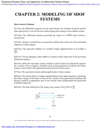
  • 1. 55 © 2012 Cengage Learning. All Rights Reserved. May not be scanned, copied or duplicated, or posted to a publicly accessible website, in whole or in part. CHAPTER 2: MODELING OF SDOF SYSTEMS Short Answer Problems 2.1 True: the differential equations are the same because the resultant of gravity and the static spring force is zero for the case of the hanging mass-spring-viscous damper system. 2.2 False: The differential equation governing the motion of a SDOF linear system is second order. 2.3 False: Springs in parallel have an equivalent stiffness that is the sum of the individual stiffnesses of these springs. 2.4 False: The equivalent stiffness of a uniform simply supported beam at its middle is . 2.5 True: Viscous damping is often added to a system to add a linear term in the governing differential equation. 2.6 False: When the equivalent systems method is used to derive the differential equation for a system with an angular coordinate used as the generalized coordinate the kinetic energy is used to derive the equivalent moment of inertia of the system. 2.7 True: The equivalent systems method applied only to linear systems. 2.8 False: The inertia effects of simply supported beam can be approximated by calculating the kinetic energy of the beam in terms of the velocity of the generalized coordinate and placing a particle of appropriate mass at the location whose displacement the generalized coordinate represents. 2.9 False: The static deflection of the spring in the system of Fig. SP2.9 is .   Mechanical Vibrations Theory and Applications 1st Edition Kelly Solutions Manual Full Download: http://alibabadownload.com/product/mechanical-vibrations-theory-and-applications-1st-edition-kelly-solutions-ma This sample only, Download all chapters at: alibabadownload.com
  • 2. Chapter 2: Modeling of SDOF Systems   56 © 2012 Cengage Learning. All Rights Reserved. May not be scanned, copied or duplicated, or posted to a publicly accessible website, in whole or in part. 2.10 False: The springs in the system of Fig. SP2.10 are in parallel (the springs have the same displacement, x, and the resultant force on the FBD of the block is the sum of the spring forces). 2.11 True: A shaft is an elastic member in which an angular displacement occurs when acted on by a torque. The angular displacement has a value of / . 2.12 True: The equivalent viscous damping coefficient is calculated by comparing the energy dissipation in the combination of viscous dampers to that of an equivalent viscous damper. 2.13 False: The added mass of a fluid entrained by a vibrating system is determined by calculating the kinetic energy developed in the fluid. 2.14 False: If it is desired to calculate the reactions at the support of Fig SP2.14 the effects of the static spring force and gravity cancel and do need to be included on the FBD or in summing forces on the FBD (the cancelling of static spring forces with gravity only applies to the derivation of the differential equation). 2.15 False: Gravity does not cancel with the static spring force in the system of Figure SP2.15 and hence the potential energy of both is included in potential energy calculations. (Assuming small the potential energy in the spring is . The potential energy due to gravity assuming the datum is the pin support is sin ). 2.16 The small angle assumption is used to linearize nonlinear systems a priori. If the angular displacement is small it is assumed that sin , cos 1, tan in derivation of the differential equation. 2.17 FBD's are drawn at an arbitrary instant for derivation of differential equations. 2.18 A quadratic form is form of kinetic energy equal to when used to apply the equivalent systems method to derive a differential equation. The potential energy has a quadratic form of . 2.19 The inertia effects of the spring in a mass-spring-viscous damper system can be approximated by adding a particle of 1/3 the mass of the spring to the point on the system where the spring is attached. 2.20 Each spring in a parallel combination has the same displacement. 2.21 The equivalent stiffness of a combination of springs is calculated by requiring the total potential energy of the combination when written in terms of the displacement of the
  • 3. Chapter 2: Modeling of SDOF Systems  57 © 2012 Cengage Learning. All Rights Reserved. May not be scanned, copied or duplicated, or posted to a publicly accessible website, in whole or in part. particle where the equivalent spring is to be attached is equal to the potential energy of a spring of equivalent stiffness placed at that location. 2.22 The FBD is shown at an arbitrary instant. 2.23 At an arbitrary instant the upper bar has rotated through an angle , measured positive clockwise. The lower bar has an angular displacement , measure counterclockwise. The displacements of the particles must be the same where the rigid bar is attached, or . The FBDs are shown at an arbitrary instant.             2.24 The equivalent systems method is used to derive the differential equation for linear SDOF systems. It can be used to model a linear SDOF system with an equivalent mass- spring-viscous damper model. Using a linear displacement as the generalized coordinate the equivalent mass, the equivalent stiffness, the equivalent damping viscous damping coefficient and the equivalent force are determined using the kinetic energy, potential energy, energy dissipated by viscous dampers and the work done by non-conservative forces. 2.25 Static spring forces not drawn on the FBD of external forces when they cancel with a source of potential energy for a linear system and the generalized coordinate is measured from the system's equilibrium position. 2.26 No, the equivalent systems method cannot be used for a nonlinear system.
  • 4. Chapter 2: Modeling of SDOF Systems   58 © 2012 Cengage Learning. All Rights Reserved. May not be scanned, copied or duplicated, or posted to a publicly accessible website, in whole or in part. 2.27 Given: Springs of individual stiffness’s and placed in series. The equivalent stiffness of the combination is . 2.28 Given: System of Figure SP2.28. The diagrams showing the reduction to a single spring of equivalent stiffness of . 2.29 Given: System of Figure 2.29. The aluminum shaft is in series with the steel shaft (angular displacements add). The stiffness of the aluminum shaft is . . 2.10 10 N·m/rad . The stiffness of the steel shaft is . . 1.06 10 N·m/rad. The equivalent stiffness is / / 6.94 10 N·m/rad. 2.30 Given: F = 300 N ∆ 1 mm. The stiffness of the element is ∆ N . 3 10 N/m. 2.31 Given: F=300 N ∆ 1 mm. The potential energy is ∆ 3 105 N/m20.001 m2 0.15 J. 2.32 Given: F=300 N ∆ 1 mm. The potential energy is the same for a compressive force as for a tensile force. The potential energy is ∆ 3 10 N/m 0.001 m 0.15 J. 2.33 Given: 250 N · , 2°. The potential energy developed in the spring is 250 N · 2° ° 0.153 J.
  • 5. Chapter 2: Modeling of SDOF Systems  59 © 2012 Cengage Learning. All Rights Reserved. May not be scanned, copied or duplicated, or posted to a publicly accessible website, in whole or in part. 2.34 Given: G = 80 × 10 N/m L = 2.5 m , = 10 cm, 15 cm The polar moment of inertia is 0.15 0.1 6.38x10 m . The torsional stiffness of the shaft is . N/ . 2.04 10 N · m/rad. 2.35 Given: G = 40 × 10 N/m , L 1.8 m, r = 25 cm. The polar moment of inertia is 0.25 6.12 10 m . The torsional stiffness of the shaft is . N/ . 1.36 10 N · m/rad. 2.36 Given: E = 200 × 10 N/m , L 2.3 m, rectangular cross-section 5 cm × 6 cm. The longitudinal stiffness of the bar is . . N/ . 2.61 10 N/m. 2.37 Given: E = 200 × 10 N/m , L = 10 , beam of rectangular cross section of width 1 and height 0.5 . The stiffness of a cantilever beam at its end is N/ . / = 6.25 N/m. 2.38 Given: k = 4000 N/m, m=20 kg. The static deflection of the spring is ∆ . / N/ 4.91 cm 2.39 Given: ℓ 10 cm, 2.3 g/cm, m = 150 g. The mass of the spring is ℓ 2.3 g/cm 0.1 m 0.023 kg 23 g. The added mass is 7.67 g. 2.40 Given: System of Figure SP2.40. The inertia effects of the springs are approximated by adding a particle of mass /3 to the center of the disk and a particle of mass /3 to the suspended block. The total kinetic energy of the system is . The kinetic energy of the block and the second spring is The angular displacement of the pulley is and its kinetic energy is The displacement of the center of the disk is . The disk rolls
  • 6. Chapter 2: Modeling of SDOF Systems   60 © 2012 Cengage Learning. All Rights Reserved. May not be scanned, copied or duplicated, or posted to a publicly accessible website, in whole or in part. without slipping, . The kinetic energy of the first spring is . The total kinetic energy of the system is . 2.41 Given: System of Figure SP2.41. The work done by the viscous dampers as the system rotates through an angle is  .    2.42 (a) sin 0.05 = 0.05; (b) cos 0.05 = 1; (c) 1-cos 0.05 = 0.05 /2 = 0.00125; (d) tan 0.05 = 0.05; (e) cot 0.05 = 1/tan 0.05 = 1/0.05 = 20; (f) sec 0.05 = 1/cos 0.05 = 1; (g) csc 0.05 = 1/sin 0.05 = 20 2.43 (a) sin 3° = 6 /360 = /60; (b) cos 3° = 1; (c) 1-cos 3° = ; (d) tan 3° = /60 2.44 Given: System of Figure 2.44. The kinetic energy of the system is 2.45 (a)-(vi); (b)-(iii); (c)-(iv); (d)-(vii); (e)-(i); (f)-(iv); (g)-(v); (h)-(ii)          
  • 7. Chapter 2: Modeling of SDOF Systems  61 © 2012 Cengage Learning. All Rights Reserved. May not be scanned, copied or duplicated, or posted to a publicly accessible website, in whole or in part. Chapter Problems 2.1 Determine the equivalent stiffness of a linear spring when a SDOF mass- spring model is used for the system shown in Figure P2.1 with x being the chosen generalized coordinate. Given: L = 2 m, E = 200 × 109 N/m2 , I = 1.15 × 10⁻⁴ m4 , m = 20 kg Find: keq Solution: The deflection of a pinned-pinned beam at its midspan is determined using Table D.2 with a = L/2, Z = L/2 as EI48 L 2LZy 3 == )/( The equivalent stiffness is the reciprocal of the deflection, m N 101.38 (2m) )m10)(1.15 m N 1048(20 48 8 3 44 2 9 3 ×= ×× = = − L EI keq Problem 2.1 illustrates the determination of the equivalent stiffness of a structural member. 2.2 Determine the equivalent stiffness of a linear spring when a SDOF mass-spring model is used for the systems shown in Figure P2.2 with x being the chosen generalized coordinate. Given: k, E, I, L Find: keq Solution: The cantilever beam behaves as a linear spring. The displacement of the end of the upper spring and the end of the cantilever beam are the same. Thus the beam is in parallel with the upper spring. The equivalent stiffness of the cantilever beam at its end is
  • 8. Chapter 2: Modeling of SDOF Systems   62 © 2012 Cengage Learning. All Rights Reserved. May not be scanned, copied or duplicated, or posted to a publicly accessible website, in whole or in part. 3b L EI3 k = Thus the equivalent stiffness of the beam and spring in parallel is k L EI3 k 3eq1 += The total deflection of the system is the deflection of the beam plus the change in length of the lower spring. Thus the lower spring is in series with the beam and upper spring. Using the equation for a series combination of springs 3 3 3 eq eq L EI3 k2 L EI3 kk L EI3 k 1 k 1 1 k 1 k 1 1 k 1 + ⎟ ⎠ ⎞ ⎜ ⎝ ⎛ + = + + = + = Problem 2.2 illustrates (a) principles for determining parallel and series combination of springs and (b) use of the formulas for series and parallel spring combinations. 2.3 Determine the equivalent stiffness of a linear spring when a SDOF mass-spring model is used for the the system shown in Figure P2.3 with x being the chosen generalized coordinate. Given: Fixed-pinned beam with overhang, dimensions shown Find: keq. Solution: The 20 kg machine is placed at A on the beam. Using the displacement of A as the generalized coordinate, the equivalent stiffness is the reciprocal of the displacement at A due to a unit concentrated load at A. From Table D2, with a = 0.6m, z1 = 1.0 m, the displacement at A due to a unit concentrated load at A is
  • 9. Chapter 2: Modeling of SDOF Systems  63 © 2012 Cengage Learning. All Rights Reserved. May not be scanned, copied or duplicated, or posted to a publicly accessible website, in whole or in part. ( ) 43 2 2 3 1 CaC 2 a C 6 a CazEIy +++== (1) where   568 z a 1 2 1 z a 2 3 2 3 C 3 11 1 .−=⎟⎟ ⎠ ⎞ ⎜⎜ ⎝ ⎛ −++−=   (2)    1680 z a 11 z a 1 2 z C 2 11 1 2 .= ⎥ ⎥ ⎦ ⎤ ⎢ ⎢ ⎣ ⎡ ⎟⎟ ⎠ ⎞ ⎜⎜ ⎝ ⎛ −−⎟⎟ ⎠ ⎞ ⎜⎜ ⎝ ⎛ −=   (3)    0C3 =   (4)    0C4 =   (5)  Substituting eqs.(2)-(5) in eq.(l) leads to ( ) ( ) ( ) 01083 2 60 1680 6 60 53860zEIy 23 . . . . .. =+−== Hence the equivalent stiffness is ( ) EI392 EI 010830 1 60zy 1 keq . .. . == = = Problem 2.3 illustrates the concept of equivalent stiffness for a one degree of freedom model of a mass attached to a beam. The equations and entries of Table D2 are used to determine the equivalent stiffness. 2.4 Determine the equivalent stiffness of a linear spring when a SDOF mass-spring model is used for the system shown in Figure P2.4 with x as the chosen generalized coordinate.   Given: system shown Solution: The stiffness of the fixed-free beam is 3 3 210 10 N/m 6.1 10 m 2.5 m 2.50 10 N/m
  • 10. Chapter 2: Modeling of SDOF Systems   64 © 2012 Cengage Learning. All Rights Reserved. May not be scanned, copied or duplicated, or posted to a publicly accessible website, in whole or in part. The stiffness of the pinned-pinned beam is 48 48 210 10 N/m 6.1 10 m 2.5 m 3.94 10 N/m The equivalent stiffness is given by the model shown below. The upper beam acts in series with the upper spring (the displacements of the springs add to given the displacement of the midspan of the simply supported beam). The lower beam acts in series with the middle spring (their displacements add). The upper spring combination acts in parallel with the lower beam-spring combination. Both act in parallel with the spring below the mass. The equivalent stiffness of the upper beam and spring is , 1 1 3.94 10 1 6 10 7.11 10 N/m The equivalent stiffness of the lower spring and beam is , 1 1 2.5 10 1 1 10 5.91 10 N/m The equivalent stiffness of the combination is 7.11 10 N m 5.91 10 N m 8 10 N m 2.10 10 N/m Problem 2.4 illustrates the equivalent stiffness of a combination of springs. 2.5 Determine the equivalent stiffness of a linear spring when a SDOF mass-spring model is used for the system shown in Figure P2.5 with x as the chosen generalized coordinate. Given: system shown Given: Solution: The potential energy of a spring of equivalent stiffness located at the point whose displacement is x is 1 2 The potential energy of the system, using x as a generalized coordinate, is
  • 11. Chapter 2: Modeling of SDOF Systems  65 © 2012 Cengage Learning. All Rights Reserved. May not be scanned, copied or duplicated, or posted to a publicly accessible website, in whole or in part. 1 2 3 1 2 5 3 1 2 4 1 2 196 9 Thus the equivalent stiffness is 196 9 Problem 2.5 illustrates the equivalence of two systems of springs using potential energy. 2.6 Determine the equivalent stiffness of a linear spring when a SDOF mass-spring model is used for the system shown in Figure P2.6 with x as the chosen generalized coordinate. Given: system shown Given: Solution: The potential energy of a spring of equivalent stiffness located at the point whose displacement is x is 1 2 The potential energy of the system, using x as a generalized coordinate, is 1 2 1 2 2 1 2 3 1 2 10 9 Thus the equivalent stiffness is 10 9 Problem 2.6 illustrates the equivalence of two systems of springs using potential energy.   2.7 Determine the equivalent stiffness of a linear spring when a SDOF mass-spring model is used for the system shown in Figure P2.7 with x as the chosen generalized coordinate.
  • 12. Chapter 2: Modeling of SDOF Systems   66 © 2012 Cengage Learning. All Rights Reserved. May not be scanned, copied or duplicated, or posted to a publicly accessible website, in whole or in part. Given: system shown Given: Solution: The potential energy of a spring of equivalent stiffness located at the point whose displacement is x is 1 2 The angular displacement of the upper bar is , measured positive clockwise. The angular displacement of the lower bar is , measured positive counterclockwise. The particles attached to the rigid link have the same displacement 2 3 Noting that 4 3 thus 9 8 The potential energy of the system, using x as a generalized coordinate, is 1 2 1 2 3 8 1 2 3 4 1 2 2 3 8 1 2 127 64 Thus the equivalent stiffness is 127 64 Problem 2.7 illustrates the equivalence of two systems of springs using potential energy. 2.8 Determine the equivalent stiffness of a linear spring when a SDOF mass-spring model is used for the system shown in Figure P2.8 with x as the chosen generalized coordinate. Given: system shown
  • 13. Chapter 2: Modeling of SDOF Systems  67 © 2012 Cengage Learning. All Rights Reserved. May not be scanned, copied or duplicated, or posted to a publicly accessible website, in whole or in part. Given: Solution: The potential energy of a spring of equivalent stiffness located at the point whose displacement is x is 1 2 The spring attached to the disk and around the pulley has a displacement of 3x, x from the displacement of the mass center and 2x (assuming no slip between the disk and the surface) from the angular rotation of the disk. The potential energy of the system, using x as a generalized coordinate, is 1 2 3 1 2 3 1 2 12 Thus the equivalent stiffness is 12 Problem 2.8 illustrates the equivalence of two systems of springs using potential energy. 2.9 Two helical coil springs are made from a steel E 200 10 N/m bar of radius 20 mm. One spring has a coil diameter of 7 cm; the other has a coil diameter of 10 cm. The springs have 20 turns each. The spring with the smaller coil diameter is placed inside the spring with the larger coil diameter. What is the equivalent stiffness of the assembly? Given: E 200 10 N/m (or 80 10 N/m , r = 20 mm, 7 cm, 10 cm, 20 Find: Solution: The stiffness of the inner spring is 64 80 10 N/m 0.07 m 64 20 0.02 1.88 10 N/m The stiffness of the outer spring is 64 80 10 N/m 0.10 m 64 20 0.02 7.81 10 N/m The springs act in parallel, the displacements are the same and the force on the block is the sum of the forces in the springs. Thus 1.88 10 N m 7.81 10 N m 9.69 10 N m
  • 14. Chapter 2: Modeling of SDOF Systems   68 © 2012 Cengage Learning. All Rights Reserved. May not be scanned, copied or duplicated, or posted to a publicly accessible website, in whole or in part. Problem 2.9 illustrates springs acting in parallel. 2.10 A thin disk attached to the end of an elastic beam has three uncoupled modes of vibration. The longitudinal motion, the transverse motion, and the torsional oscillations are kinematically independent. Calculate the following of Figure P2.10. (a) The longitudinal stiffness; (b) The transverse stiffness; (c) The torsional stiffness Given: L = 65 cm, r = 10 mm, E = 200 × 109 N/m2 , G = 80 × 109 N/m2 Find: kl, kθ, and ky Solution: The geometric properties of the beam are ( ) ( ) ( ) 4944 4844 2422 m107.58m0.01 44 m101.57m0.01 22 m103.14m0.01π − − − ×=== ×=== ×=== ππ ππ π rI rJ rA (a) The longitudinal stiffness is ( ) m N 109.67 m0.65 m N 10200m103.14 7 2 924 ×= ⎟ ⎠ ⎞ ⎜ ⎝ ⎛ ×× == − L AE kl (b) The transverse stiffness is ( ) ( ) m N 101.72 m0.65 m107.85 m N 102003 3 4 3 49 2 9 3 ×= ×⎟ ⎠ ⎞ ⎜ ⎝ ⎛ × == − L EI ky (c) The torsional stiffness is ( ) rad mN 1930 m0.65 m N 1080m101.57 2 948 ⋅ = ⎟ ⎠ ⎞ ⎜ ⎝ ⎛ ×× == − L JG kθ Problem 2.10 illustrates three independent modes of vibration of a cantilever beam.
  • 15. Chapter 2: Modeling of SDOF Systems  69 © 2012 Cengage Learning. All Rights Reserved. May not be scanned, copied or duplicated, or posted to a publicly accessible website, in whole or in part. 2.11 Find the equivalent stiffness of the springs in Figure P2.11 in the x direction. Given: springs shown Find: Solution: A FBD of the particle at an arbitrary instant is shown Summing forces on the FBD in the x direction leads to 4 10 0.866 3 10 0.707 5 10 0.707 9.12 10 Hence the equivalent stiffness in the x direction is 9.12 10 N m Problem 2.11 illustrates the determination of an equivalent stiffness when springs act on a particle at different angles. 2.12 A bimetallic strip used as a MEMS sensor is shown in Figure P2.12. The strip has a length of 20 . The width of the strip is 1 m. It has an upper layer made of steel 210 10 N/m and a lower layer made of aluminum 80 10 N/m . Each layer is 0.1 m thick. Determine the equivalent stiffness of the strip in the axial direction. Given: L = 20 m, w = 1 m, 210 10 N/m , 80 10 N/m , t = 0.1 m Find:
  • 16. Chapter 2: Modeling of SDOF Systems   70 © 2012 Cengage Learning. All Rights Reserved. May not be scanned, copied or duplicated, or posted to a publicly accessible website, in whole or in part. Solution: The two layers behave as longitudinal springs in parallel. The layers have the same displacement and the forces from the layers add. The equivalent stiffness of a longitudinal spring is The strips have the same area and same length. The equivalent stiffness is the sum of the individual stiffnesses thus 210 10 N m 80 10 N/m 1 μm 0.1 μm 20 μm 1450 N m Problem 2.12 illustrates equivalent stiffness of spring in series. 2.13 A gas spring consists of a piston of area A moving in a cylinder of gas. As the piston moves, the gas expands and contracts, changing the pressure exerted on the piston. The process occurs adiabatically (without heat transfer) so that where p is the gas pressure, is the gas density, is the constant ratio of specific heats, and C is a constant dependent on the initial state. Consider a spring when the initial pressure is and the initial temperature is . At this pressure, the height of the gas column in the cylinder is h. Let be the pressure force acting on the piston when it has displaced a distance x into the gas from its initial height. (a) Determine the relation between and x. (b) Linearize the relationship of part (a) to approximate the air spring by a linear spring. What is the equivalent stiffness of the spring? (c) What is the required piston area for an air spring ( 1.4 to have a stiffness of 300 N·m for a pressure of 150 kPa (absolute) with h = 30 cm. Given: , , , , (c) k=300 N/m, 150 kPa, h=0.3 m, 1.4 Find: (a) and x relation (b) k (c) A Solution: (a) The ideal gas law is used to find the density in the initial state The initial volume of gas in the spring is
  • 17. Chapter 2: Modeling of SDOF Systems  71 © 2012 Cengage Learning. All Rights Reserved. May not be scanned, copied or duplicated, or posted to a publicly accessible website, in whole or in part. The total mass of the air is When the piston has moved a distance x from its equilibrium position at an arbitrary time Since the total mass of the gas is constant the density becomes The initial state is defined by At an arbitrary time (b) The force exerted on the piston is . Thus 1 But from a binomial expansion 1 1 Thus (c) Solving for A and substituting given values 300 N/m 0.3 m 1.4 150000 N/m 4.29 10 m Problem 2.13 illustrates the linearized stiffness for an air spring.
  • 18. Chapter 2: Modeling of SDOF Systems   72 © 2012 Cengage Learning. All Rights Reserved. May not be scanned, copied or duplicated, or posted to a publicly accessible website, in whole or in part. mg = F = Lhr Ldr( 1+d/h) ρ ρθ wg 2.14 A wedge is floating stably on an interface between a liquid of mass density ρ, as shown in Figure P2.14. Let x be the displacement of the wedge’s mass center when it is disturbed from equilibrium. (a) What is the buoyant force acting on the wedge? (b) What is the work done by the buoyant force as the mass center of the wedge moves from x1 and x2? (c) What is the equivalent stiffness of the spring if the motion of the mass center of the wedge is modeled by a mass attached to a linear spring? Given: ρ, ρw, r, L, h Find: FB, W, linear system Solution: (a) Consider a free-body diagram of the wedge as it floats in equilibrium on the free surface. Let d be the depth of the wedge into the liquid. In this state the buoyant force must balance with the gravity force ⎟ ⎠ ⎞ ⎜ ⎝ ⎛ += =⎟ ⎠ ⎞ ⎜ ⎝ ⎛ + =− h d 1dh gLhr h d 1Ldr 0WF w w B ρρ ρρ (1) Now consider the wedge as it oscillates on the free surface. The buoyant force at an arbitrary time is ( ) ⎥ ⎦ ⎤ ⎢ ⎣ ⎡ +++⎟ ⎠ ⎞ ⎜ ⎝ ⎛ += ⎟ ⎠ ⎞ ⎜ ⎝ ⎛ + ++= h x xx h d 2 h d 1dgLr h xd 1rxdgLF 2 B ρ ρ (b) The work done by the buoyant force as the center of mass moves between x1 and x2 is dx h x xx h d 2 h d 1dgLr dxFW 2x x x x B21 2 1 2 1 ⎥ ⎦ ⎤ ⎢ ⎣ ⎡ +++⎟ ⎠ ⎞ ⎜ ⎝ ⎛ + == ∫ ∫→ ρ
  • 19. Chapter 2: Modeling of SDOF Systems  73 © 2012 Cengage Learning. All Rights Reserved. May not be scanned, copied or duplicated, or posted to a publicly accessible website, in whole or in part. ( ) ( ) ( ) ( )⎥ ⎦ ⎤ ⎢ ⎣ ⎡ −+−+−+−⎟ ⎠ ⎞ ⎜ ⎝ ⎛ +=→ 3 1 3 2 2 1 2 2 2 1 2 21221 xx h3 1 xx 2 1 xx h d xx h d 1dgLrW ρ (c)The system cannot be modeled as a mass attached to a linear spring. The buoyant force is conservative. However when its potential energy function is formulated, it is not a quadratic function of the generalized coordinate. Problem 2.14 illustrates the nonlinear oscillations of a wedge on the interface between a liquid and a gas. 2.15 Consider a solid circular shaft of length L and radius c made of an elastoplastic material whose shear stress– shear strain diagram is shown in Figure P2.15(a). If the applied torque is such that the shear stress at the outer radius of the shaft is less than τp, a linear relationship between the torque and angular displacement exists. When the applied torque is large enough to cause plastic behavior, a plastic shell is developed around an elastic core of radius r < c, as shown in Figure P2.15(b). Let (1) be the applied torque which results in an angular displacement of θδ τ θ += cG Lp (2) (a) The shear strain at the outer radius of the shaft is related to the angular displacement c Lcγ θ = (3) The shear strain distribution is linear over a given cross section. Show that this implies (4) (b) The torque is the resultant moment of the shear stress distribution over the cross section of the shaft, ρπτρ d2T c 0 2 ∫= (5) Use this to relate the torque to the radius of the elastic core. (c) Determine the relationship between δT and δθ. (d) Approximate the stiffness of the shaft by a linear torsional spring. What is the equivalent torsional stiffness?
  • 20. Chapter 2: Modeling of SDOF Systems   74 © 2012 Cengage Learning. All Rights Reserved. May not be scanned, copied or duplicated, or posted to a publicly accessible website, in whole or in part. c r pτ Given: stress-strain diagram, τ > τp Find: Show eq. (4), linear approximation to stiffness Solution: (a) The shear stress is linear in the elastic core and at ρ = r, γ = τp /G. The shear strain is linear throughout the cross section. Thus rG p ρτ γ = (6) Then evaluating eq. (6) at ρ = c and using eq. (3) rG L L c rG C p p c τ θ θτ γ = == (b) The shear stress distribution over the cross section is shown. The resisting torque is the resultant moment of the shear stress distribution. But ⎪ ⎩ ⎪ ⎨ ⎧ ≤≤ ≤≤ = cr r0 r p p ρτ ρ ρ τ τ , , Hence from eq.(5) ⎟⎟ ⎠ ⎞ ⎜⎜ ⎝ ⎛ −= +⎟ ⎠ ⎞ ⎜ ⎝ ⎛ = ∫∫ 12 r 3 c 2 d2d2 r T 33 p 2 c x p 2 p r 0 p πτ ρπρτρρπτ ρ τ (7) (c) Equating the torques from eq. (1) and eq. (7) ( ) 3 1 p 3 33p 3 p 33 p T6 cr rc 6 T T 2 c 12 r 3 c 2 ⎟ ⎟ ⎠ ⎞ ⎜ ⎜ ⎝ ⎛ −= −= +=⎟⎟ ⎠ ⎞ ⎜⎜ ⎝ ⎛ − πτ δ τ πδ δπτπτ (8) Equating the angular displacement. from eqs. (2) and (4)
  • 21. Chapter 2: Modeling of SDOF Systems  75 © 2012 Cengage Learning. All Rights Reserved. May not be scanned, copied or duplicated, or posted to a publicly accessible website, in whole or in part. rG L cG L pp τ δθ τ =+ (9) Substituting eq.(8) into eq.(9) 3 1 p 3 pp T6 cG L cG L ⎟ ⎟ ⎠ ⎞ ⎜ ⎜ ⎝ ⎛ − =+ πτ δ τ δθ τ (10) (d) Note that 3 1 3 P 3 1 P 3 c T6 1 c 1T6 c −− ⎟⎟ ⎠ ⎞ ⎜⎜ ⎝ ⎛ −=⎟⎟ ⎠ ⎞ ⎜⎜ ⎝ ⎛ − πτ δ πτ δ Then using the binomial theorem assuming small δT and keeping only the first two terms leads to ⎟⎟ ⎠ ⎞ ⎜⎜ ⎝ ⎛ +=⎟⎟ ⎠ ⎞ ⎜⎜ ⎝ ⎛ − − 3 P 3 1 P 3 c T2 1 c 1T6 c πτ δ πτ δ (11) Substituting eq.(11) in eq. (10) leads to ⎟⎟ ⎠ ⎞ ⎜⎜ ⎝ ⎛ +=+ 3 P PP c T2 1 cG L cG L πτ δτ δθ τ or L JG L2 GcT Gc TL2 4 4 == = π δθ δ π δ δθ The above approximation neglected terms involving powers of δT when the binomial expansion was performed. Thus, a linear approximation to the stiffness is the same as the linear stiffness. Problem 2.15 illustrates a linear approximation to torsional stiffness for an elastoplastic material when the elastic shear stress is exceeded.
  • 22. Chapter 2: Modeling of SDOF Systems   76 © 2012 Cengage Learning. All Rights Reserved. May not be scanned, copied or duplicated, or posted to a publicly accessible website, in whole or in part. 2.16 A bar of length L and cross-sectional area A is made of a material whose stress-strain diagram is shown in Figure P2.16. If the internal force developed in the bar is such that σ < σp, then the bar’s stiffness for a SDOF model is L AE k = Consider the case when σ > σp. Let P = σpA + δP be the applied load which results in a deflection ∆ ∆. (a) The work done by the applied force is equal to the strain energy developed in the bar. The strain energy per unit volume is the area under the stress–strain curve. Use this information to relate δP to δΔ. (b) What is the equivalent stiffness when the bar is approximated as a linear spring for σ > σp? Given: stress-strain curve, δP, E, σp Find: δΔ = f (δP), linear stiffness approximation Solution: The work done by application of a force P, resulting in a deflection Δ is Δ= P 2 1 W (1) When the stress exceeds the proportional limit, the work is written as ( ) ⎟ ⎠ ⎞ ⎜ ⎝ ⎛ Δ++= δ σ δσ E L PA 2 1 W P P The work is also the area under the P- Δcurve. ( ) ( ) ∈∈+⎟ ⎠ ⎞ ⎜ ⎝ ⎛ = ∫ Δ + dALf E L A 2 1 W LE E PP P P δσ σ σσ (2) Equating the work from eqs.(1) and (2) leads to ( ) ∈∈=Δ++ ∫ Δ + dALfP 2 1 AA 2 1 E L P 2 1 LE E PP P P δσ σ δδδσσδ (3) σ σ δ δΔ p p PA E L A 1 2 L
  • 23. Chapter 2: Modeling of SDOF Systems  77 © 2012 Cengage Learning. All Rights Reserved. May not be scanned, copied or duplicated, or posted to a publicly accessible website, in whole or in part. (b) If δΔ is small, then so is δP. Hence the term with their product is much smaller than the other terms in eq. (3) and is neglected. In addition the mean value theorem is used to approximate the integral ( ) ( )∈ Δ ∈=∈∫ Δ + ~ALf L dALf LE E P P δ δσ σ where EEE PP δσσ Δ +≤∈≤~ Then eq. (5) becomes ( )∈Δ=Δ+Δ+ ~fAP 2 1 A 2 1 E L P 2 1 PP δδδδσσδ Dividing by δΔ leads to ( )∈+−= Δ ~f L AE2 L AEP Pσδ δ If the limit as δΔ →0 is taken then ( ) P P f E σ σ →∈ →∈ ~ ~ and L AEP → Δδ δ Problem 2.16 illustrates the linear approximation to the stiffness when the elastic strength is exceed for a bar undergoing longitudinal oscillations. 2.17 Calculate the static deflection of the spring in the system of Figure P2.17.
  • 24. Chapter 2: Modeling of SDOF Systems   78 © 2012 Cengage Learning. All Rights Reserved. May not be scanned, copied or duplicated, or posted to a publicly accessible website, in whole or in part. mg O Oy x STK(a sinθ δ) STθ Given: k, m1, m2, r1, r2 Find: ΔST Solution: Summing moments about the center of the pulley using the free body diagram of the system when it is equilibrium, 1 21 ST 1ST21 0 kr grm rkgrm 0M =Δ Δ−= =∑ Problem 2.17 illustrates calculation of the static deflection of a spring. 2.18 Determine the static deflection of the spring in the system of Figure P2.18. Given: L = 1.6 m, a = 1.2 m, m = 20 kg, k = 5 × 10³ N/m, spring is stretched 20 mm when bar is vertical. Find: ΔST. Solution: A free body diagram of the bar in its static equilibrium position is shown. It is assumed the spring force is horizontal. The equilibrium position is defined by θST, the clockwise angle made by the bar with the vertical. Summing moments about the support 0M0 =∑ leads to ( ) 0aak 2 L amg STSTST =−+⎟ ⎠ ⎞ ⎜ ⎝ ⎛ −− ... cossinsin θδθθ Substituting given values and rearranging leads to 5317491 STST .sin.tan .. −= θθ The above equation is solved by trial and error for θST. yielding rad0.01680.965o . ==STθ m g m R 1 p ΔK ST
  • 25. Chapter 2: Modeling of SDOF Systems  79 © 2012 Cengage Learning. All Rights Reserved. May not be scanned, copied or duplicated, or posted to a publicly accessible website, in whole or in part. The static deflection in the spring is given by 0.22mmsin .. =−=Δ δθSTST a Problem 2.18 illustrates the application of the equations of equilibrium to determine the static equilibrium position for a given system. The assumption that the spring force is horizontal is good, in light of the result. Equation (1) was solved by trial and error. An alternate method is to approximate tanθ by θ and sinθ by θ. 2.19 A simplified SDOF model of a vehicle suspension system is shown in Figure P2.19. The mass of the vehicle is 500 kg. The suspension spring has a stiffness of 100,000 N/m. The wheel is modeled as a spring placed in series with the suspension spring. When the vehicle is empty, its static deflection is measured as 5 cm. (a) Determine the equivalent stiffness of the wheel (b) Determine the equivalent stiffness of the spring combination Given: m = 500 kg, ks = 100,000 N/m, δ = 5 cm Find: (a) kw (b) keq Solution: (a) The wheel is in series with the suspension spring. The force developed in each spring is the same while the total displacement of the series combination is the sum of the displacements of the individual springs. When the system is in equilibrium, the springs are subject to the empty weight of the vehicle. Hence the force developed in each spring is equal to the weight of the vehicle W = mg = (500 kg)(9.81 m/s2 ) = 4.905 × 10³ N. The total displacement in the two springs is 5 cm, cm5=+ sw δδ But the force developed in a linear spring is kδ. Thus cm5=+ ws k mg k mg Solving for kw leads to N/m1016.5 N/m000,100 1 N10905.4 m05.011 6 3 ×= − × =−= w sw k kmgk δ (b) The equivalent stiffness of the series combination is
  • 26. Chapter 2: Modeling of SDOF Systems   80 © 2012 Cengage Learning. All Rights Reserved. May not be scanned, copied or duplicated, or posted to a publicly accessible website, in whole or in part. N/m1063.9 N/m1016.5 1 N/m101 1 1 11 1 4 65 ×= × + × = + = eq ws eq k kk k   Problem 2.19 illustrates the equivalent stiffness of two springs placed in series.   2.20 The spring of the system in Figure P2.20 is unstretched in the position shown. What is the deflection of the spring when the system is in equilibrium? Given: m = 150 kg, k = 2000 N/m, E = 210 × 10 N/m , I = 8.2 × 10 m , L = 3 m Find: ∆ Solution: The system behaves as two springs in parallel. The beam has the same displacement as the spring. The equivalent stiffness is 3 3 210 10 N/m 8.2 10 m 3 m 2000 N m 2.11 10 N/m  The static deflection of the system is ∆ 150 kg 9.81 m/s 2.11 10 N/m 6.97 cm  Problem 2.20 illustrates springs in parallel and static deflection. 2.21 Determine the static deflection of the spring in the system of Figure P2.21.  Given: m, k, E, I, L Find: ∆ Solution: The system behaves as two springs in parallel. The beam has the same displacement as the spring. The equivalent stiffness is 48  
  • 27. Chapter 2: Modeling of SDOF Systems  81 © 2012 Cengage Learning. All Rights Reserved. May not be scanned, copied or duplicated, or posted to a publicly accessible website, in whole or in part. The static deflection is ∆ 48 48 Problem 2.21 illustrates the concepts of springs in parallel and static deflection of springs.   2.22 Determine the static deflections in each of the springs in the system of Figure P2.22. Given: 1 10 N/m, 2 10 N/m, m = 4 kg, a = 0.4 m, b = 0.2 m Find: ∆ , ∆ Solution: A FBD of the system is shown when the system is in equilibrium       Summing forces on the FBD leads to 0 ∆ ∆   Summing moments about the mass center yields 0 ∆ ∆   Solution of the equations leads to ∆ 1 4 kg 9.81 m/s 1 10 N/m 1 0.4 m 0.2 m 0.131 mm  ∆ 1 4 kg 9.81 m/s 2 10 N/m 1 0.2 m 0.4 m 0.131 mm  Problem 2.22 illustrates the determination of static deflections from the equations of static equilibrium.
  • 28. Chapter 2: Modeling of SDOF Systems   82 © 2012 Cengage Learning. All Rights Reserved. May not be scanned, copied or duplicated, or posted to a publicly accessible website, in whole or in part. 2.23 A 30 kg compressor sits on four springs, each of stiffness 1 × 10 N/m. What is the static deflection of each spring? Given: m = 30 kg, 1 10 N/m, n = 4 Find: ∆ Solution: The compressor sits on four identical springs. Thus the equivalent stiffness of the springs is that of four springs in parallel or 4 4 1 10 N/m 4 10 N/m  The static deflection of the compressor is ∆ 30 kg 9.81 m/s 4 10 N/m 0.736 mm  Problem 2.23 illustrates the static deflection of a machine mounted on four springs in parallel.   2.24 The propeller of a ship is a tapered circular cylinder, as shown in Figure P2.24. When installed in the ship, one end of the propeller is constrained from longitudinal motion relative to the ship while a 500-kg propeller mass is attached to its other end. (a) Determine the equivalent longitudinal stiffness of the shaft for a SDOF model. (b) Assuming a linear displacement function along the shaft, determine the equivalent mass of the shaft to use in a SDOF model. Given: r0 = 30 cm, r1 = 20 cm, E = 210 × 109 N/m2 , mp = 500 kg, ρ = 7350 kg/m3 , L = 10 m Find: keq, meq Solution: The equivalent system is that of a mass meq attached to a linear spring of stiffness keq . The equivalent mass is calculated to include inertia effects of the shaft. The equivalent stiffness is the reciprocal of the deflection at the end of the shaft due to the application of a unit force. From strength of materials, the change in length of the shaft due to a unit load is   ∫= L 0 AE dx δ   Let x be a coordinate along the axis of the shaft, measured from its fixed end. Then
  • 29. Chapter 2: Modeling of SDOF Systems  83 © 2012 Cengage Learning. All Rights Reserved. May not be scanned, copied or duplicated, or posted to a publicly accessible website, in whole or in part.   ( ) x01030x L rr rxr 10 0 .. −= − −=   is the local radius of the shaft. Thus   ( ) E 0553 Ex01030 dx L 0 2 . .. = − = ∫π δ   Hence the equivalent stiffness is   m N 103.96 05.53 9 ×== E keq   Let u(x) represent the displacement of a particle in the cross section a distance x from the fixed end due to a load P applied at the end. From strength of materials   ( ) ( ) E P x x xE dxP AE dxP xu xx π π 3 10 01.03.0 01.03.00 2 0 − = − == ∫∫   Let z = u(L), then   ( ) x01030 x 50 z xu 50 z E3 P10 E3 P10 50 E3 P10 20 10 z .. . − = = == π ππ   Consider a differential element of mass dm = ρAdx, located a distance x from the fixed end. The kinetic energy of the differential element is   ( ) ( )dxxAxu 2 1 dT 2 ρ&=   The total kinetic energy of the shaft is
  • 30. Chapter 2: Modeling of SDOF Systems   84 © 2012 Cengage Learning. All Rights Reserved. May not be scanned, copied or duplicated, or posted to a publicly accessible website, in whole or in part.   ( ) ( ) ( ) ( ) ( ) 2 2 10 0 2 2 2 210 0 2 0 2 kg3288 2 1 25003 1000 2 1 5000 01.03.0 01.03.0502 2 1 z z dxx z dx x xz dxxAxuT m m L & & & & & = = = −⎟ ⎠ ⎞ ⎜ ⎝ ⎛ − ⎟ ⎠ ⎞ ⎜ ⎝ ⎛ = = ∫ ∫ ∫ πρ ρπ π ρ ρ   Hence the equivalent mass is 3288 kg. Problem 2.24 illustrates the modeling of a non-uniform structural element using one- degree-of-freedom   2.25 (a) Determine the equivalent torsional stiffness of the propeller shaft of Problem 2.24. (b) Determine an equivalent moment of inertia of the shaft to be placed on the end of the shaft for a SDOF model of torsional oscillations. Given: r0 = 30 cm, r1 = 20 cm, E = 80 × 109 N/m2 , mp = 500 kg, ρ = 7350 kg/m3 , L = 10 m Find: kteq, Ieq Solution: The equivalent system is that of a disk of moment of inertia Ieq attached to a torsional spring of stiffness kteq . The equivalent mass is calculated to include inertia effects of the shaft. The equivalent stiffness is the reciprocal of the deflection at the end of the shaft due to the application of a unit force. From strength of materials, the change in length of the shaft due to a unit load is   ∫= L JG dx 0 θ   Let x be a coordinate along the axis of the shaft, measured from its fixed end. Then
  • 31. Chapter 2: Modeling of SDOF Systems  85 © 2012 Cengage Learning. All Rights Reserved. May not be scanned, copied or duplicated, or posted to a publicly accessible website, in whole or in part.   ( ) x01030x L rr rxr 10 0 .. −= − −=   is the local radius of the shaft. Thus the moment of inertia of the shaft is   ( ) GGx dx L 1866 01.03.0 2 0 4 = − = ∫π θ   Hence the equivalent stiffness is   m/radN104.28 1866 7 ⋅×== G keq   Let (x) represent the displacement of a particle in the cross section a distance x from the fixed end due to a moment M applied at the end. From strength of materials   ( ) ( ) ( ) G M x xG dxM JG dxM x xx π π θ 3 20 3.0 1 01.03.0 1 01.03.0 2 33 0 4 0 ⎟⎟ ⎠ ⎞ ⎜⎜ ⎝ ⎛ − − = − == ∫∫   Let z = (L), then   ( ) ( ) ⎟⎟ ⎠ ⎞ ⎜⎜ ⎝ ⎛ − − = = 33 3.0 1 01.03.0 1 96.87 3 20 96.87 x z x G MP z θ π   Consider a differential element of mass, located a distance x from the fixed end. The kinetic energy of the differential element is   ( ) ( )dxxJxdT ρθ 2 2 1 &=   The total kinetic energy of the shaft is   . . . . . . . 0.3 0.01   The equivalent moment of inertia is determined from 1 2 1 2 392.5 kg · m  
  • 32. Chapter 2: Modeling of SDOF Systems   86 © 2012 Cengage Learning. All Rights Reserved. May not be scanned, copied or duplicated, or posted to a publicly accessible website, in whole or in part. x m m, ,K Ks s1 21 2 Problem 2.25 illustrates the modeling of a non-uniform structural element using one- degree-of-freedom 2.26 A tightly wound helical coil spring is made from an 1.88-mm diameter bar made from 0.2 percent hardened steel (G = 80 × 109 N/m2 , ρ = 7600 kg/m3 ). The spring has a coil diameter of 1.6 cm with 80 active coils. Calculate (a) the stiffness of the spring, (b) the static deflection when a 100 g particle is hung from the spring, and (b) (c) the equivalent mass of the spring for a SDOF model. Given: G = 80 × 109 N/m2 , ρ = 7600 kg/m3 , D = 1.88 mm, r = 8 mm, N = 80, m = 100 g Find: (a) Δst (b) meq Solution: The stiffness of the helical coil spring is N/m2.381 )m008.0)(80(64 )m00188.0)(N/m1080( 64 3 429 3 4 = × = = k k Nr GD k   When the 100-g particle is hung from the spring its static deflection is mm8.3==Δ k mg st   (b) The total mass of the spring is g8.77 4 1 )2( 2 = = s s m DNrm ππρ   The equivalent mass of the system is g9.125 3 1 = += eq seq m mmm   Problem 2.26 illustrates (a) the stiffness of a helical coil spring, (b) the static deflection of a spring, and (c) the equivalent mass of a spring used to approximate its inertia effects.
  • 33. Chapter 2: Modeling of SDOF Systems  87 © 2012 Cengage Learning. All Rights Reserved. May not be scanned, copied or duplicated, or posted to a publicly accessible website, in whole or in part. x m 3 s1 2.27 One end of a spring of mass ms1 and stiffness k1 is connected to a fixed wall, while the other end is connected to a spring of mass ms2 and stiffness k2. The other end of the second spring is connected to a particle of mass m. Determine the equivalent mass of these two springs. Given: k1, ms1, k2, ms2 Find: meq Solution: Let x be the displacement of the block to which the series combination of springs is attached. The inertia effects of the left spring can be approximated by placing a particle of mass ms1/3 at the joint between the two springs. Define a coordinate z1, measured along the axis of the left spring and a coordinate z2, measured along the axis of the right spring. Let u1(z1) be the displacement function the left spring and u2(z2) be the displacement function in the right spring. It is assumed that the springs are linear and the displacements are linear,   ( ) ( ) dczzu bazzu 222 111 += +=   (1)  where the constants a, b, c, and d are determined from the following conditions (a) Since the left end of the left spring is attached to the wall   ( ) 00u1 =   This immediately yields b = 0. (b) The right end of the right spring is attached to the block which has a displacement x   ( ) xu 22 =l   (2) where l2 is the unstretched length of the right spring. (c) The displacement is continuous at the intersection between the two springs.   ( ) ( )0uu 211 =l   (3)  where l1 is the unstretched length of the left spring. (d) Since the springs are in series, the forces developed in the springs must be the same.   ( ) ( ) ( )[ ]0uukuk 2222111 −= ll   (4)  Using eq. (2)-(4) in eq. (l) leads to
  • 34. Chapter 2: Modeling of SDOF Systems   88 © 2012 Cengage Learning. All Rights Reserved. May not be scanned, copied or duplicated, or posted to a publicly accessible website, in whole or in part. md s2 2l   21 2 21 1 2 21 2 1 kk xk d kk kx c kk kx a + = + = + = l l   The kinetic energy of the left spring is   ( ) 2 2 21 21s 2 2 1 1s 1 x kk k 3 m 2 1 u 3 m 2 1 T &l& ⎟⎟ ⎠ ⎞ ⎜⎜ ⎝ ⎛ + ==   Thus the contribution to the equivalent mass from the left spring is   2 21 21s 1eq kk k 3 m m ⎟⎟ ⎠ ⎞ ⎜⎜ ⎝ ⎛ + =   The displacement function in the right spring becomes   ( ) ⎟⎟ ⎠ ⎞ ⎜⎜ ⎝ ⎛ + + = 2 2 1 21 22 k z k kk x zu l   Consider a differential element of length dz2 in the right spring, a distance z2 from the spring’s left end. The kinetic energy of the element is   22 2 2 2 2s 2 dzzu m 2 1 dT )(& l =   The total kinetic energy of the spring is   ( ) ( ) ( )2 211 3 2 3 212s 2 0 2 2 2 12 21 2 2 2s 2 kkk kkk 3 m 2 1 dzk z k kk xm 2 1 T 2 + −+ = ⎟⎟ ⎠ ⎞ ⎜⎜ ⎝ ⎛ + + = ∫ l l & l   Hence the equivalent mass of the series spring combination is   ( ) ⎪⎭ ⎪ ⎬ ⎫ ⎪⎩ ⎪ ⎨ ⎧ ⎥ ⎥ ⎦ ⎤ ⎢ ⎢ ⎣ ⎡ ⎟⎟ ⎠ ⎞ ⎜⎜ ⎝ ⎛ −⎟⎟ ⎠ ⎞ ⎜⎜ ⎝ ⎛ ++ + = 3 1 2 3 1 2 2s 2 11s 2 22 21 eq k k k k 1mkmk kk3 1 m   Problem 2.27 illustrates the equivalent mass of springs in series.
  • 35. Chapter 2: Modeling of SDOF Systems  89 © 2012 Cengage Learning. All Rights Reserved. May not be scanned, copied or duplicated, or posted to a publicly accessible website, in whole or in part. 2.28 A block of mass m is connected to two identical springs in series. Each spring has a mass m and a stiffness k. Determine the equivalent mass of the two springs at the mass. Given: Two identical springs in series Find: Solution: Let x be the displacement of the block to which the series combination of springs is attached. The inertia effects of the left spring can be approximated by placing a particle of mass ms1/3 at the joint between the two springs. Define a coordinate z1, measured along the axis of the left spring and a coordinate z2, measured along the axis of the right spring. Let u1(z1) be the displacement function the left spring and u2(z2) be the displacement function in the right spring. It is assumed that the springs are linear and the displacements are linear,   ( ) ( ) dczzu bazzu 222 111 += +=   (1)  where the constants a, b, c, and d are determined from the following conditions (a) Since the left end of the left spring is attached to the wall    ( ) 00u1 =   This immediately yields b = 0. (b) The right end of the right spring is attached to the block which has a displacement x   ( ) xu =l2   (2)  where l2 is the unstretched length of the right spring. (c) The displacement is continuous at the intersection between the two springs.   ( ) ( )021 uu =l   (3)  where l1 is the unstretched length of the left spring. (d) Since the springs are in series, the forces developed in the springs must be the same.   ( ) ( ) ( )[ ]0221 uukku −= ll   (4) Using eqs. (2)-(4) in eq. (l) leads to 2 3ℓ 3   The kinetic energy of the second spring is
  • 36. Chapter 2: Modeling of SDOF Systems   90 © 2012 Cengage Learning. All Rights Reserved. May not be scanned, copied or duplicated, or posted to a publicly accessible website, in whole or in part. 1 2 ℓ ℓ 18ℓ 2 ℓ 1 ℓ 1 2 13 27   The total kinetic energy is 1 2 3 3 1 2 13 27 1 2 14 27   Thus 14 27   Problem 2.28 illustrates the calculation of the equivalent mass of a system. 2.29 Show that the inertia effects of a torsional shaft of polar mass moment of inertia J can be approximated by adding a thin disk of moment of inertia J/3 at the end of the shaft. Given: J Find: Solution: The angular displacement due to a moment M applied at the end of the shaft varies over the length of the shaft according to   At the end of the shaft . Thus the moment at the end of the shaft is and   The differential element of the shaft is where J is the polar mass moment of inertia of the shaft. The kinetic energy is 1 2 1 2 1 2 3   The kinetic energy of the shaft has the form . Hence 3   Problem 2.29 illustrates the equivalent moment of inertia of a shaft using a SDOF model of the shaft.
  • 37. Chapter 2: Modeling of SDOF Systems  91 © 2012 Cengage Learning. All Rights Reserved. May not be scanned, copied or duplicated, or posted to a publicly accessible website, in whole or in part. L/2 E,I m L/2 2.30 Use the static displacement of a simply supported beam to determine the mass of a particle that should be added at the midspan of the beam to approximate inertia effects in the beam. Given: m = 20 kg, mb = 12 kg, E = 200 × 109 N/m2 , I = 1.15 × 10⁻⁴ m4 , L = 2 m Find: meq Solution: the inertia effects of the beam are approximated by placing a particle of appropriate mass at the location of the block. The mass of the particle is determined by equating the kinetic energy of the beam to the kinetic energy of a particle placed at the location of the block. The kinetic energy of the beam is approximated using the static beam deflection equation. For a pinned-pinned beam, the deflection equation valid between the left support and the location of the block is obtained using Table D.2. In using Table D.2, set a = L/2. Note that Table D.2 gives results for unit loads which can be multiplied by the magnitude of the applied load to attain the deflection due to any concentrated load. Thus the deflection of a pinned-pinned beam due to a concentrated load P applied at a = L/2 is   ( ) ⎟⎟ ⎠ ⎞ ⎜⎜ ⎝ ⎛ +−= 16 zL 12 z EI P zy 23   Let w be the deflection of the block, located at z = L/2. Thus   ( ) 3 3 L z48 EI P EI48 PL 2Lyw = ==   Hence   ( ) ⎟⎟ ⎠ ⎞ ⎜⎜ ⎝ ⎛ −= 2 2 L z 43 L wz zy   Consider a differential element of mass dm = ρAdz. The kinetic energy of the differential mass is   ( ) Adzzy 2 1 dT 2 b ρ&=   Since the beam is symmetric about its midspan the kinetic energy of the mass to the right of the midspan is equivalent to the kinetic energy of the mass to the left of the midspan. Thus the total kinetic energy of the beam is
  • 38. Chapter 2: Modeling of SDOF Systems   92 © 2012 Cengage Learning. All Rights Reserved. May not be scanned, copied or duplicated, or posted to a publicly accessible website, in whole or in part.   dz L z 43 L zw A2 2 1 dT2T 2 2 L 0 2 22 2L 0 bb ∫ ∫ ⎟⎟ ⎠ ⎞ ⎜⎜ ⎝ ⎛ −⎟ ⎠ ⎞ ⎜ ⎝ ⎛ = = & ρ   Evaluation of the integral yields   ( ) ( ) 2 b 2 b wm4920 2 1 wAL4920 2 1 T .. == ρ   Hence the equivalent mass is   bm4860mm .+=   Problem 2.30 illustrates determination of the equivalent mass of a pinned-pinned beam. 2.31 Determine the equivalent mass or equivalent moment of inertia of the system shown in Figure P2.31 when the indicated generalized coordinate is used.   Given: x, m, r Find: Solution: The kinetic energy of the system is the kinetic energy of the hanging block plus the kinetic energy of the sphere. The velocity of the mass center of the sphere is related to the velocity of the block by 2   The total kinetic energy of the system assuming no slip between the sphere and the surface ( ) and knowing that the moment of inertia of a sphere is 1 2 1 2 2 1 2 2 5 2 1 2 27 20   The kinetic energy of the system is related to the equivalent mass by . Thus 27 20   Problem 2.31 illustrates the equivalent mass of a system.
  • 39. Chapter 2: Modeling of SDOF Systems  93 © 2012 Cengage Learning. All Rights Reserved. May not be scanned, copied or duplicated, or posted to a publicly accessible website, in whole or in part. 2.32 Determine the equivalent mass or equivalent moment of inertia of the system shown in Figure P2.32 when the indicated generalized coordinate is used.   Given: x, m, L Find: Solution: The total kinetic energy of the system is 1 2 2 1 2 1 2 1 2   where y is the displacement of the cart of mass m, z is the displacement of the mass center of the bar and measures the angular rotation of the bar. Kinematics is employed to obtain that if x is the displacement of the cart of mass 2m then assuming small 2 3   3 2   6 4   Thus the kinetic energy becomes noting that 1 2 2 1 2 2 1 2 4 1 2 1 12 3 2 1 2 5 2   The kinetic energy of the system is related to the equivalent mass by . Thus 5 2   Problem 2.32 illustrates the equivalent mass of a SDOF system. 2.33 Determine the equivalent mass or equivalent moment of inertia of the system shown in Figure P2.33 when the indicated generalized coordinate is used.  
  • 40. Chapter 2: Modeling of SDOF Systems   94 © 2012 Cengage Learning. All Rights Reserved. May not be scanned, copied or duplicated, or posted to a publicly accessible website, in whole or in part. Given: m, L, Find: Solution: The relative velocity equation is used to relate the angular velocity of bar BC and the velocity of the collar at C to the angular velocity of bar AB. cos sin sin cos   v 2 cos sin sin 2 sin cos 2 cos   The law of sines is used to determine that sin 2 sin   Then cos 1 4 sin   Setting the j component to zero leads to 2 cos cos   The x component leads to sin 2 sin sin cos tan   The relative velocity equation is used between particle B and the mass center of bar BC leading to sin 4 sin cos 4 cos   The kinetic energy of the system is 1 2 2 1 2 1 12 1 2 sin 4 sin cos 4 cos 1 2 1 12 sin cos tan   The equivalent moment of inertia is calculated for a linear system by . This system is linear only for small .
  • 41. Chapter 2: Modeling of SDOF Systems  95 © 2012 Cengage Learning. All Rights Reserved. May not be scanned, copied or duplicated, or posted to a publicly accessible website, in whole or in part. Problem 2.33 illustrates that the concept of equivalent mass does not work for nonlinear systems. 2.34 Determine the equivalent mass or equivalent moment of inertia of the system shown in Figure 2.34 when the indicated generalized coordinate is used.   Given: system shown Find: Solution: The total kinetic energy of the system is 1 2 1 2 1 12 1 2 1 2 1 12 1 2   where is the angle made by the lower bar with the horizontal. The displacement of the particle on the upper bar that is connected to the rigid link in the same as the displacement of the lower bar that is connected to the link 4 5 5 4   Substituting into the kinetic energy leads to 1 2 2 1 2 1 12 1 2 2 5 4 1 2 1 12 5 4 1 2 3 5 4 1 2 37 36   The equivalent moment of inertia when is used as the generalized coordinate is 37 36   Problem 2.34 illustrates calculation of an equivalent moment of inertia. 2.35 Determine the equivalent mass or equivalent moment of inertia of the system shown in Figure P2.35 when the indicated generalized coordinate is used.  
  • 42. Chapter 2: Modeling of SDOF Systems   96 © 2012 Cengage Learning. All Rights Reserved. May not be scanned, copied or duplicated, or posted to a publicly accessible website, in whole or in part. Given: shafting system with rotors Find: Given: The relation between the angular velocities of the shafts is given by the gear equation     The kinetic energy of the shafting system is 1 2 1 2 1 2 1 2   The equivalent moment of inertia is   Problem 2.35 illustrates calculation of an equivalent moment of inertia of a shafting system. 2.36 Determine the kinetic energy of the system of Figure P2.36 at an arbitrary instant in terms of x& including inertia effects of the springs.   Given: system shown with x as generalized coordinate Find: T Solution: Let θ be the clockwise angular displacement of the pulley and let x1 be the displacement of the center of the disk, both measured from the equilibrium position of the system. Inertia effects of a spring are approximated by imagining a particle of one-third of
  • 43. Chapter 2: Modeling of SDOF Systems  97 © 2012 Cengage Learning. All Rights Reserved. May not be scanned, copied or duplicated, or posted to a publicly accessible website, in whole or in part. the mass of the spring at the location where the spring is attached to the system. The kinetic energy of the system at an arbitrary instant is 2 1 2222 1 22 3 1 2 1 3 1 2 1 2 2 1 2 1 2 2 1 2 1 2 1 xmxmmrxmIxmT ssDDp &&&&& +++++= ωθ   Kinematics leads to 2 2 1 x x r x = =θ   Since the disk rolls without slip DD D r x r x 2 1 && ==ω   Substitution into the expression for kinetic energy leads to 2 2 2 2 2 2 22 2 4 1 44 7 2 1 23 1 2 1 3 1 2 1 2 2 2 1 2 1 2 2 2 1 22 1 2 1 xm r I mT x mxm r x mr x m r x IxmT s p ss D Dp & & & &&& & ⎟ ⎟ ⎠ ⎞ ⎜ ⎜ ⎝ ⎛ ++= ⎟ ⎠ ⎞ ⎜ ⎝ ⎛ ++ ⎟⎟ ⎠ ⎞ ⎜⎜ ⎝ ⎛ +⎟ ⎠ ⎞ ⎜ ⎝ ⎛ +⎟ ⎠ ⎞ ⎜ ⎝ ⎛ +=   Problem 2.36 illustrates the determination of the kinetic energy of a one-degree-of-freedom system at an arbitrary instant in terms of a chosen generalized coordinate and the approximation for inertia effects of springs. 2.37 The time-dependent displacement of the block of mass m of Figure P2.36 is m)4sin(03.0)( 35.1 tetx t− = . Determine the time-dependent force in the viscous damper if c = 125 N·s/m.   Given: x(t), c = 125 N·s/m Find: F
  • 44. Chapter 2: Modeling of SDOF Systems   98 © 2012 Cengage Learning. All Rights Reserved. May not be scanned, copied or duplicated, or posted to a publicly accessible website, in whole or in part. Solution: The viscous damper is attached to the center of the disk. If x1 is the displacement of the center of the disk, then kinematics leads to x1 = x/2. The force developed in the viscous damper is [ ] N))4cos(4)4sin(45.1(875.1 ))4cos(4)4sin(35.1()03.0( 2 s/m-N125 ))4cos(4)4sin(35.1()03.0( 2 2 35.1 35.1 35.1 1 tteF tteF tte c F x c xcF t t t +−= +−= +−= == − − − &&   Problem 2.37 illustrates the force developed in a viscous damper. 2.38 Calculate the work done by the viscous damper of Problem 2.37 between t = 0 and t = 1 s.   Given: x(t), c=125 N-s/m, 0 < t < 1 s Find: W    Solution: The time dependent force in the viscous damper is determined in Chapter Problem 2.37 as The work done by the force is ∫−= 1)( dxtFW   where x1 is the displacement of the point in the system where the viscous damper is attached. It is noted that m4sin015.0)( 2 1 )( 35.1 1 tetxtx t− ==   Using the chain rule for differentials dtxdt dt dx dx 1 1 1 &==   It is noted that xcF &= . Thus N))4cos(4)4sin(45.1(875.1 35.1 tteF t +−= −
  • 45. Chapter 2: Modeling of SDOF Systems  99 © 2012 Cengage Learning. All Rights Reserved. May not be scanned, copied or duplicated, or posted to a publicly accessible website, in whole or in part. τdm = rdA dA r dt2 1∫−= xcW &   m-N0.004211W dt)4(sin0281.0 2 1 0 7.2 −= −= ∫ − teW t   Problem 2.38 illustrates the work done by a viscous damping force.   2.39 Determine the torsional viscous-damping coefficient for the torsional viscous damper of Figure P2.39. Assume a linear velocity profile between the bottom of the dish and the disk.   Given: θ, h, ρ, μ Find: ct Solution: Assume the disk is rotating with an angular velocityθ&. The velocity of a particle on the disk, a distance r away from the axis of rotation is   θ&rv=   Solution: Assume the disk is rotating with an angular velocityθ&. The velocity of a particle on the disk, a distance r away from the axis of rotation is   θ&rv=   A velocity gradient exists in the fluid due to the rotation of the plate. Assume the depth of the plate is small enough such that the fluid velocity profile is linear between the bottom of the dish and the disk. The no-slip condition implies that a fluid particle adjacent to the disk, a distance r from the center of rotation has a velocity rθ while a fluid particle adjacent to the bottom of the dish has zero velocity. Hence the velocity gradient is   h r dy dv θ& =   The velocity gradient leads to a shear stress from the fluid on the dish. The shear stress is calculated using Newton’s viscosity law as
  • 46. Chapter 2: Modeling of SDOF Systems   100 © 2012 Cengage Learning. All Rights Reserved. May not be scanned, copied or duplicated, or posted to a publicly accessible website, in whole or in part.   h r dy dv θμ μτ & ==   The resisting moment acting on the disk due to the shear stress distribution is   ( ) θ πμ θ θμ θττ π π & & h2 R drdr h drdrrdArM 4 3 2 0 R 0 2 0 R 0 = = == ∫∫ ∫∫∫   Hence the torsional damping coefficient is   h2 R C 4 t πμ =   Problem 2.39 illustrates a type of torsional viscous damper. 2.40 Determine the torsional viscous-damping coefficient for the torsional viscous damper of Figure P2.40. Assume a linear velocity profile in the liquid between the fixed surface and the rotating cone. Given: h, d, r, ρ, μ Find: ct Solution: Let y be a coordinate measured from the tip of the cone, positive upward. Assume the cone is rotating with an angular velocity θ& . The velocity of a particle on the outer surface of the cone is   ( )θ&yRv =   where R(y) is the distance from the surface to the axis of the cone. From geometry   ( ) h ry yR =   Hence,   h ry v θ& =  
  • 47. Chapter 2: Modeling of SDOF Systems  101 © 2012 Cengage Learning. All Rights Reserved. May not be scanned, copied or duplicated, or posted to a publicly accessible website, in whole or in part. Assume that d is small enough such that the velocity distribution in the fluid is linear. Let z be a coordinate normal to the surface of the cone. Then using the no-slip condition between the fluid and the cone’s surface and between the fluid and the fixed surface gives   ( ) d z h ry zv θ& =   The velocity gradient produces a shear stress on the surface of the cone. Using Newton’s viscosity law   hd ry dz dv θμ μτ & ==     Consider a differential slice of the cone of thickness dy. The shear stress acts around the surface of the slice, causing a resisting moment about the center of the cone of   ( )( ) dy dh yr2 dyyR2ydM 2 32 θμπ τπ & = =   Thus the total resisting moment is   θ μπ θμπ & & d2 hr dyy dh r2 dMM 22 h 0 3 2 2 = == ∫ ∫   Hence the torsional viscous damping coefficient for this configuration is   d2 hr c 22 t μπ =   Problem 2.40 illustrates determination of the torsional viscous damping coefficient for a specific configuration.   2.41 Shock absorbers and other forms of viscous dampers use a piston moving in a cylinder of viscous liquid as illustrated in Figure P2.41. For this configuration the force developed on the piston is the sum of the viscous forces acting on the side of the piston and the force due to the pressure difference between the top and bottom surfaces of the piston. R(y) dy
  • 48. Chapter 2: Modeling of SDOF Systems   102 © 2012 Cengage Learning. All Rights Reserved. May not be scanned, copied or duplicated, or posted to a publicly accessible website, in whole or in part. (a) Assume the piston movers with a constant velocity vp. Draw a free-body diagram of the piston and mathematically relate the damping force, the viscous force, and the pressure force. (b) Assume steady flow between the side of the piston and the side of the cylinder. Show that the equation governing the velocity profile between the piston and the cylinder is      (1)   (c) Assume the vertical pressure gradient is constant. Use the preceding results to determine the velocity profile in terms of the damping force and the shear stress on the side of the piston. (d) Use the results of part (c) to determine the wall shear stress in terms of the damping force. (e) Note that the flow rate between the piston and the cylinder is equal to the rate at which the liquid is displaced by the piston. Use this information to determine the damping force in terms of the velocity and thus the damping coefficient. (f) Use the results of part (e) to design a shock absorber for a motorcycle that uses SAE 1040 oil and requires a damping coefficient of 1000 N·m/s. Given: vp, d, D, h, μ, ρ, (f) SAE 1040 oil, c = 1000 N·m/s Find: (a) - (e) ceq, (f) design damper Solution: (a) The free body diagram of the piston at an arbitrary instant shown below illustrates the pressure force acting on the upper top and bottom surfaces of the piston, the viscous force which is the resultant of the shear stress distribution acting around the circumference of the piston, and the reaction force in the piston rod. F F F P D Dh 4 π πτ = = pu v w u 2 4 D PF 2 P π ll =   Assuming the inertia force of the piston is small, summation of forces acting on the piston leads to   vpup FFFF +−= l   where
  • 49. Chapter 2: Modeling of SDOF Systems  103 © 2012 Cengage Learning. All Rights Reserved. May not be scanned, copied or duplicated, or posted to a publicly accessible website, in whole or in part.   ( ) DhF 4 D ppFF wv 2 upup πτ π = −=− ll   Hence   ( ) Dh 4 D ppF w 2 u πτπ +−= l   (b) Consider a differential ring of height dx and thickness dr, a distance r from the center of the position. Consider a free body diagram of the element rr x x p p p p drdr dx dx r p p r ττ τ τ δτδτ d d δδ d d ++ + +   Summation of forces acting of the element leads to   ( ) ( ) rdx dp 0dxr2dr r drr2pdx dx dp p ∂ ∂ −= =⎟ ⎠ ⎞ ⎜ ⎝ ⎛ − ∂ ∂ ++⎟ ⎠ ⎞ ⎜ ⎝ ⎛ −+ τ πτ τ τπ   If the fluid is Newtonian   r v ∂ ∂ −= μτ   where v( r, x) is the velocity distribution in the fluid. Thus   2 2 r v dx dp ∂ ∂ = μ   (c) Assume dp/dx = C, a constant. Then from the preceding equation   21 2 crcr 2 c v ++= μ   where c1 and c2 are constants of integration. The boundary conditions are   ( ) ( ) 0dRv v2DRv =+ ==    Application of the boundary conditions leads to
  • 50. Chapter 2: Modeling of SDOF Systems   104 © 2012 Cengage Learning. All Rights Reserved. May not be scanned, copied or duplicated, or posted to a publicly accessible website, in whole or in part.   ( ) ( )RdR 2 C d R 1vc dR2 2 C d v c 2 2 1 ++⎟ ⎠ ⎞ ⎜ ⎝ ⎛ += ++−= μ μ   Using Newton’s viscosity law   ( ) ⎟ ⎠ ⎞ ⎜ ⎝ ⎛ −= +==−= d v d 2 C 2 d C d v Rr dr dv w w μτ μμτ   Note that since the pressure is constant   h pp dx dp u− = l   Hence the damping force becomes   2 2 w d2 hDv d2 D 1DhF πμ πτ −⎟ ⎠ ⎞ ⎜ ⎝ ⎛ +=   (d) Note that the flow rate must be equal to the velocity of the piston times the area of the piston   v 4 D Q 2 π=   The flow rate is also calculated by   ( ) ⎥ ⎦ ⎤ ⎢ ⎣ ⎡ +⎟ ⎠ ⎞ ⎜ ⎝ ⎛ +−⎟ ⎠ ⎞ ⎜ ⎝ ⎛ −= = ∫ + 243 w dR R vd 6 1 d 3 2 Rd 6 1 d v d 1 2 drr2rvQ μτ μ π π   Equating Q from the previous two equations and solving for the wall shear stress leads to   ( ) ( )d8Dd2 d12dD2D3v 2 22 w − −− = μ τ   and leads to   ( ) ( ) v d8Dd4 d24dDD3hD F 3 323 − −− = πμ   which leads to the damping coefficient
  • 51. Chapter 2: Modeling of SDOF Systems  105 © 2012 Cengage Learning. All Rights Reserved. May not be scanned, copied or duplicated, or posted to a publicly accessible website, in whole or in part. ( ) ( )d8Dd4 d24dDD3Dh c 3 323 − −− = μπ   If D>>d, the preceding equation is approximated by   3 3 d4 hD3 c πμ =   Corrections to the above equation in powers of d/D can be obtained by expanding the reciprocal of the denominator in powers of d/D using a binomial expansion, multiplying by the numerator, simplifying and collecting coefficients on like powers of d/D. (e) The viscosity of SAE 1040 oil is approximately 0.4 N·s / m2 Assume h = 0.5 mm and d = 10 mm. Then setting c = 1000 N·s/m and assuming D >> d leads to   ( ) ( ) ( ) m0.374 3 01.04 0005.04.0 1000 3 3 = = D D π   Problem 2.41 illustrates (a) the derivation of the viscous damping coefficient for a piston- cylinder dashpot, and (b) the use of the equation for the viscous damping coefficient to design a viscous damper for a given situation. 2.42 Derive the differential equation governing the motion of the one degree-of-freedom system by applying the appropriate form(s) of Newton’s laws to the appropriate free-body diagrams. Use the generalized coordinates shown in Figure P2.42. Linearize nonlinear differential equations by assuming small displacements. Given: x as generalized coordinate, m, k Find: differential equation Solution: Free-body diagrams of the system at an arbitrary time are shown below.
  • 52. Chapter 2: Modeling of SDOF Systems   106 © 2012 Cengage Learning. All Rights Reserved. May not be scanned, copied or duplicated, or posted to a publicly accessible website, in whole or in part.   Summing forces acting on the block   ( ) ( )effext FF ∑∑ =   gives   0x m k3 x 0kx3xm xmkx2kx =+ =+ =−− && && &&   Problem 2.42 illustrates application of Newton’s law to derive the differential equation governing free vibration of a one-degree-of-freedom system. 2.43 Derive the differential equation governing the motion of the one degree-of-freedom system by applying the appropriate form(s) of Newton’s laws to the appropriate free-body diagrams. Use the generalized coordinates shown in Figure P2.43. Linearize nonlinear differential equations by assuming small displacements. Given: x as generalized coordinate, k, m, I, r Find: differential equation Solution: Since x is measured from the system’s equilibrium position, gravity cancels with the static spring forces in the governing differential equation. Thus, for purposes of deriving the differential equation, both are ignored. It is assumed there is no slip between the cable and the pulley. Thus the angular rotation of the pulley is kinematically related to the displacement of the block by   r2 x =θ   Free-body diagrams of the system are shown below at an arbitrary instant. mg K K2 N m : x =x x EXTERNAL FORCES EFFECTIVE FORCES
  • 53. Chapter 2: Modeling of SDOF Systems  107 © 2012 Cengage Learning. All Rights Reserved. May not be scanned, copied or duplicated, or posted to a publicly accessible website, in whole or in part.   Summing moments about the center of the pulley   ( ) ( )effcextc MM ∑∑ =   leads to   ( ) ( ) 0 2 22 0 2 1 2 2 2 2 2 1 2 = ⎟ ⎠ ⎞ ⎜ ⎝ ⎛ + + =+⎟ ⎠ ⎞ ⎜ ⎝ ⎛ + +=− x r I m k x krxx r I rm x r I rxmrkx && && &&&&   Problem 2.43 illustrates application of Newton’s law to derive the differential equation governing free vibration of a one-degree-of- freedom system. This problem also illustrates the benefits of using external and effective forces. Use of this method allows one free-body diagram to be drawn showing all effective forces. If this method were not used, one free- body diagram for the block and one free-body diagram of the pulley must be drawn. These free-body diagrams expose the tension in the pulley cable. Application of Newton’s laws to the free-body diagrams yield equations involving the unknown tension. The tension must be eliminated between the equations in order to derive the differential equation. 2.44 Derive the differential equation governing the motion of the one degree-of-freedom system by applying the appropriate form(s) of Newton’s laws to the appropriate free-body diagrams. Use the generalized coordinates shown in Figure P2.44. Linearize nonlinear differential equations by assuming small displacements. Given: k, L ,m, c Find: differential equation Kx R 2 2rmpg m : : x x I =
  • 54. Chapter 2: Modeling of SDOF Systems   108 © 2012 Cengage Learning. All Rights Reserved. May not be scanned, copied or duplicated, or posted to a publicly accessible website, in whole or in part. Solution: The small angle assumption is used. Free-body diagrams of the bar at an arbitrary instant are shown below.   Summing moments about the point of support   ( ) ( )eff0ext0 MM ∑∑ =   leads to   0 L g 7 12 m k 7 27 m c 7 3 0 4 L mgkL 16 9 cL 16 1 mL 48 7 mL 12 1 L 4 1 mL 4 1 4 L mgL 4 3 LK 4 3 L 4 1 Lc 4 1 222 2 =⎟ ⎠ ⎞ ⎜ ⎝ ⎛ +++ =⎟ ⎠ ⎞ ⎜ ⎝ ⎛ +++ +⎟ ⎠ ⎞ ⎜ ⎝ ⎛ =−⎟ ⎠ ⎞ ⎜ ⎝ ⎛ −⎟ ⎠ ⎞ ⎜ ⎝ ⎛ − θθθ θθθ θθθθθ &&& &&& &&&&&   Problem 2.44 illustrates application of Newton’s law to derive the differential equation governing the free vibrations of a one-degree-of-freed- linear system with viscous damping. 2.45 Derive the differential equation governing the motion of the one degree-of-freedom system by applying the appropriate form(s) of Newton’s laws to the appropriate free-body diagrams. Use the generalized coordinates shown in Figure P2.45. Linearize nonlinear differential equations by assuming small displacements. Given: m, c, k, L, θ as generalized coordinate Find: differential equation Solution: The small angle assumption is used. It is also noted that gravity, which causes static spring forces, causes with these static spring forces in the governing differential equation and hence both are ignored. Free-body diagrams of the bar at an arbitrary instant are shown below. EXTERNAL FORCES EFFECTIVE FORCES = mg mL mL mL 3KL c L o o y 2.x θ θ θ θ θ . 4 4 12 1 2 4 4 : :
  • 55. Chapter 2: Modeling of SDOF Systems  109 © 2012 Cengage Learning. All Rights Reserved. May not be scanned, copied or duplicated, or posted to a publicly accessible website, in whole or in part.   Summing moments about the point of support,   ( ) ( )effoexto MM ∑∑ =   leads to   0 7 30 7 18 0 8 5 8 3 48 7 12 1 444244224 3 4 3 222 2 =++ =++ +⎟ ⎠ ⎞ ⎜ ⎝ ⎛ =⎟ ⎠ ⎞ ⎜ ⎝ ⎛ −⎟ ⎠ ⎞ ⎜ ⎝ ⎛ −⎟ ⎠ ⎞ ⎜ ⎝ ⎛ −⎟ ⎠ ⎞ ⎜ ⎝ ⎛ − θθθ θθθ θθθθθθ m k m c kLcLmL mL L m LL c LL k LL c L LkL &&& &&& &&&&&&   Problem 2.45 illustrates application of Newton’s law to derive the differential equation governing the free vibration of a one-degree-of-freedom system with viscous damping. 2.46 Derive the differential equation governing the motion of the one degree-of-freedom system by applying the appropriate form(s) of Newton’s laws to the appropriate free-body diagrams. Use the generalized coordinates shown in Figure P2.46. Linearize nonlinear differential equations by assuming small displacements. Given: m, k, c, x as generalized coordinate Find: differential equation, ωn Solution: The effect of the incline is to cause a non-zero static deflection in the spring. Thus, neither the gravity force or the static spring force have any effect on the differential equation and both are ignored in drawing the free body diagrams. Assuming the disk rolls without slip, its angular acceleration is related to the acceleration of the mass center by   r x& =α   EXTERNAL FORCES EFFECTIVE FORCES = o o y x mL θ 12 1 2 : mL θ 4 : mL 2. θ 4K3L θ 4 C K L L θ θ . 2 4 2C L θ . 4 )(
  • 56. Chapter 2: Modeling of SDOF Systems   110 © 2012 Cengage Learning. All Rights Reserved. May not be scanned, copied or duplicated, or posted to a publicly accessible website, in whole or in part. Consider the free body diagrams drawn below at an arbitrary instant   Summing moments about the point of contact between the disk and the incline   ( ) ( )effcextc MM ∑∑ =   leads to   0x m3 k2 x m3 c2 x 0kxxcxm 2 3 rxm r x mr 2 1 rxckxr 2 =++ =++ +=−− &&& &&& && && &   Problem 2.46 illustrates application of Newton’s law to determine the governing differential equation for free vibrations of a one-degree-of-freedom system with viscous damping. 2.47 Derive the differential equation governing the motion of one-degree-of-freedom system by applying the appropriate form(s) of Newton’s laws to the appropriate free-body diagrams. Use the generalized coordinate shown in Figure P.2.47. Linearize nonlinear differential equations by assuming small displacements. Given: system shown Find: differential equation Solution: Free-body diagrams of the system at an arbitrary instant are shown below. k N F 1 2 r r2 C m m = :: x . x xx EXTERNAL FORCES EFFECTIVE FORCES
  • 57. Chapter 2: Modeling of SDOF Systems  111 © 2012 Cengage Learning. All Rights Reserved. May not be scanned, copied or duplicated, or posted to a publicly accessible website, in whole or in part. The displacement of each end of the rigid rod is the same. Using the small angle assumption θθ θθ 9 8 4 3 3 2 2 2 = = LL Summing moments about the pin support of the upper bar leads to ( ) ( ) θθθ θθθθ 3 4 66 6612 1 3 2 3 2 3 2 2 33 2 kLcLmL F LL mmL L F LL k LL c MM effAextA ++= +=+⎟ ⎠ ⎞ ⎜ ⎝ ⎛ −⎟ ⎠ ⎞ ⎜ ⎝ ⎛ − = ∑∑ &&& &&&&& Summing moments about the pin support of the lower bar leads to ( ) ( ) 2212 1 4 3 22 22 2 22 LL mmL L F LL cLkL MM effBextB ⎟ ⎠ ⎞ ⎜ ⎝ ⎛ +=−⎟ ⎠ ⎞ ⎜ ⎝ ⎛ −− = ∑∑ θθθθ &&&&& Substitution for F and θ2 leads to
  • 58. Chapter 2: Modeling of SDOF Systems   112 © 2012 Cengage Learning. All Rights Reserved. May not be scanned, copied or duplicated, or posted to a publicly accessible website, in whole or in part. 0 9 17 72 25 216 91 222 =++ θθθ kLcLmL &&& Rewriting the equation in standard form 0 91 408 91 75 =++ θθθ m k m c &&& Problem 2.47 illustrates the derivation of the differential equation governing the motion of a linear one-degree-of-freedom system using the free-body diagram method. 2.48 Derive the differential equation governing the motion of one-degree-of-freedom system by applying the appropriate form(s) of Newton’s laws to the appropriate free-body diagrams. Use the generalized coordinate shown in Figure P2.48. Linearize nonlinear differential equations by assuming small displacements. Given: system shown Find: differential equation Solution: Free-body diagrams of the system at an arbitrary instant are shown below Note that the force developed in the spring is proportional to the change in length of the spring. When the center of the disk is displaced a distance x from equilibrium, the end of the spring attached to the center of the disk compresses by x. When the center of the disk displaces x, the point on the disk to which the spring is attached has translated a distance x and rotated along the distance an angle θ. Assuming no slip between the disk and the
  • 59. Chapter 2: Modeling of SDOF Systems  113 © 2012 Cengage Learning. All Rights Reserved. May not be scanned, copied or duplicated, or posted to a publicly accessible website, in whole or in part. surface, θ = x/r. Hence this end of the spring has displaced 2x. The total change in length of this spring is 3x. Summing moments about the point of contact between the disk and surface leads to ( ) ( ) 019 2 3 2 1 )()2)(3(2)3(2)( 2 =++ +=−−+− = ∑∑ krxxcrxmr r x mrrxmrxkrxkrxckx MM effCextC &&& && &&& The differential equation is put into standard form by dividing by the coefficient of x&& leading to 0 3 38 3 2 =++ x m k x m c x &&& Problem 2.48 illustrates derivation of the differential equation governing the motion of a one-degree-of-freedom system using the free-body diagram method, putting the differential equation into a standard form, and determination of the natural frequency from the differential equation. 2.49 Derive the differential equation governing the motion of the one-degree-of- freedom system by applying the appropriate form(s) of Newton’s laws to the appropriate free-body diagrams. Use the generalized coordinate shown in Figure P2.49. Linearize nonlinear differential equations by assuming small displacements. Given: system shown Find: differential equation Solution: Free-body diagrams of the system at an arbitrary instant are shown below
  • 60. Chapter 2: Modeling of SDOF Systems   114 © 2012 Cengage Learning. All Rights Reserved. May not be scanned, copied or duplicated, or posted to a publicly accessible website, in whole or in part. Summing moments about the pin support leads to ( ) ( ) 0 2 1 2 1 6 5 22 2 2212 1 222222 222 2 =++ ++=⎟ ⎠ ⎞ ⎜ ⎝ ⎛ +−⎟ ⎠ ⎞ ⎜ ⎝ ⎛ +− = ∑∑ θθθ θθθθθθθ kLcLmL LL m LL mmL LL c L k LL c L k MM effOextO &&& &&&&&&&& The differential equation is put into standard form by dividing by the coefficient of θ&& leading to 0 5 3 5 3 =++ θθθ m k m c &&& Problem 2.49 illustrates the use of the free-body diagram method to derive the differential equation governing the motion of a one-degree-of-freedom system. 2.50 Derive the differential equation governing the motion of the one degree-of-freedom system by applying the appropriate form(s) of Newton’s laws to the appropriate free-body diagrams. Use the generalized coordinates shown in Figure P2.50. Linearize nonlinear differential equations by assuming small displacements.  
  • 61. Chapter 2: Modeling of SDOF Systems  115 © 2012 Cengage Learning. All Rights Reserved. May not be scanned, copied or duplicated, or posted to a publicly accessible website, in whole or in part. Given: R, r, m, φ as generalized coordinate Find: differential equation, ωn Solution: The generalized coordinate is chosen as φ, the angle made between the normal to the sphere and the surface at any instant of time. Let θ be an angular coordinate representing the angular displacement of the sphere. If the sphere rolls without slip, then the distance traveled by the mass center of the sphere is   θrx=   (1)  However, the mass center of the sphere is also traveling in a circular path of radius (R-r). Thus the distance traveled by the mass center is also equal to   φ)( rRx −=   (2)  Equating x from eqs.(1) and (2) leads to   φθ r rR− =   Now consider free body diagrams of the sphere at an arbitrary instant.   Summing moments about the point of contact,   ( ) ( )effcextc MM ∑∑ =   leads to   ( ) ( ) 0grR 5 7 rrRm r rR mr 5 2 mgr 2 =+− −+⎟ ⎠ ⎞ ⎜ ⎝ ⎛ − =− φφ φφφ sin sin && &&&&   Assuming small φ N mg F 2 5 r2 m(R-r) m ( )Rr r = :: :: EXTERNAL FORCES EFFECTIVE FORCES φ θ
  • 62. Chapter 2: Modeling of SDOF Systems   116 © 2012 Cengage Learning. All Rights Reserved. May not be scanned, copied or duplicated, or posted to a publicly accessible website, in whole or in part.   ( ) ( ) 0 rR7 g5 0grR 5 7 = − + =+− φφ φφ && &&   Problem 2.50 illustrates application of Newton’s law to derive the differential equation governing free vibration of a one-degree-of-freedom system. 2.51 Derive the differential equation governing the motion of the one-degree- of-freedom system by applying the appropriate form(s) of Newton’s laws to the appropriate free-body diagrams. Use the generalized coordinate shown in Figure P2.51. Linearize nonlinear differential equations by assuming small displacements. Given: system shown Find: differential equation
  • 63. Chapter 2: Modeling of SDOF Systems  117 © 2012 Cengage Learning. All Rights Reserved. May not be scanned, copied or duplicated, or posted to a publicly accessible website, in whole or in part. Solution: Free-body diagrams of the system at an arbitrary instant are shown below Summing moments about the point of support of the bar using the small angle assumption leads to ( ) ( ) θθ θθθθ ⎟ ⎠ ⎞ ⎜ ⎝ ⎛ ++= +=+−− = ∑∑ mg L kmLF LL mmL L F LL k L mg MM effOextO 2 1 3 2 3 1 6612 1 333 2 6 2 && &&&& Summing moments about the point of contact between the disk and the surface leads to
  • 64. Chapter 2: Modeling of SDOF Systems   118 © 2012 Cengage Learning. All Rights Reserved. May not be scanned, copied or duplicated, or posted to a publicly accessible website, in whole or in part. ( ) ( ) kxxcxmF r x mrrxmrxckxrFr MM effCextC −−−= ⎟ ⎠ ⎞ ⎜ ⎝ ⎛ +=−−− = ∑∑ &&& && &&& 2 3 2 1 2 Kinematics is used to give L xL x 3 3 == θθ Equating the two expressions for F and substituting for θ leads to 0 2 3 3 2 5 3 2 1 3 2 3 3 1 2 3 =⎟ ⎠ ⎞ ⎜ ⎝ ⎛ +++ ⎟ ⎠ ⎞ ⎜ ⎝ ⎛ ⎟ ⎠ ⎞ ⎜ ⎝ ⎛ ++⎟ ⎠ ⎞ ⎜ ⎝ ⎛ =−−− x L mg kxcxm L x mg L k L x mLkxxcxm &&& && &&& The differential equation is put into standard form by dividing by the coefficient of leading to 0 5 3 5 6 5 2 =⎟ ⎠ ⎞ ⎜ ⎝ ⎛ +++ x L g m k x m c x &&& Problem 2.51 illustrates the application of the free-body diagram method to derive the differential equation governing the motion of a one-degree-of-freedom system. 2.52 Determine the differential equations governing the motion of the system by using the equivalent systems method. Use the generalized coordinates shown in Figure P2.52. Given: system shown Find: differential equation using x as the generalized coordinate. Solution: The springs attached to the mass act as two springs in parallel. The system can be modeled by a mass attached to a spring of equivalent stiffness 3k. Thus the governing differential equation is   0kx3xm =+&&   x&&
  • 65. Chapter 2: Modeling of SDOF Systems  119 © 2012 Cengage Learning. All Rights Reserved. May not be scanned, copied or duplicated, or posted to a publicly accessible website, in whole or in part. or   0x m k 3x =+&&   Problem 2.52 illustrates the application of the equivalent system approach to derive the governing differential equation for a block attached to springs in parallel.   2.53 Determine the differential equations governing the motion of the system by using the equivalent systems method. Use the generalized coordinates shown in Figure P2.53. Given: x as generalized coordinate, k, m, I, r Find: differential equation Solution: Since x is measured from the system’s equilibrium position, gravity cancels with the static spring forces in the governing differential equation. Thus, for purposes of deriving the differential equation, both are ignored. It is assumed there is no slip between the cable and the pulley. Thus the angular rotation of the pulley is kinematically related to the displacement of the block by   r2 x =θ   The equivalent systems method is used. The system is modeled by a mass-spring system of an equivalent mass and equivalent stiffness, using the generalized coordinate, x. The kinetic energy of the equivalent system at an arbitrary time is   2 eq xm 2 1 T &=   The kinetic energy of the system at an arbitrary instant is   2 2 2 2 x r4 I m 2 1 r2 x I 2 1 xm 2 1 T & & & ⎟ ⎠ ⎞ ⎜ ⎝ ⎛ += ⎟ ⎠ ⎞ ⎜ ⎝ ⎛ +=   Requiring the kinetic energy of the equivalent system to be equal to the kinetic energy of the original system at any instant leads to
  • 66. Chapter 2: Modeling of SDOF Systems   120 © 2012 Cengage Learning. All Rights Reserved. May not be scanned, copied or duplicated, or posted to a publicly accessible website, in whole or in part.   2eq r4 I mm +=   The potential energy of the equivalent system at an arbitrary instant is   2 eq xk 2 1 V =   The potential energy of the system at hand at an arbitrary instant is   2 2 x 4 k 2 1 v 2 x k 2 1 v = ⎟ ⎠ ⎞ ⎜ ⎝ ⎛ =   Requiring the potential energies to be equal at any instant leads to   4 k keq =   The differential equation governing free vibration is   0x r4 I m4 k x 0x 4 k x r4 I m 0xkxm 2 2 eqeq = ⎟ ⎠ ⎞ ⎜ ⎝ ⎛ + + =+⎟ ⎠ ⎞ ⎜ ⎝ ⎛ + =+ && && &&   Problem 2.53 illustrates use of the equivalent system method to derive the differential equation governing free vibration of a one-degree-of- freedom system.   2.54 Determine the differential equations governing the motion of the system by using the equivalent systems method. Use the generalized coordinates shown in Figure P2.54. Given: k, m, c, θ as generalized coordinate Find: differential equation, ωn Solution: The small angle assumption is used. Since the generalized coordinate is an angular displacement the
  • 67. Chapter 2: Modeling of SDOF Systems  121 © 2012 Cengage Learning. All Rights Reserved. May not be scanned, copied or duplicated, or posted to a publicly accessible website, in whole or in part. system is modeled by a disk of mass moment of inertia Ieq attached to a shaft of torsional stiffness kt,eq and connected to a torsional viscous damper of torsional damping coefficient ct,eq. The kinetic energy of the system at an arbitrary time is   22 22 2 22 mL 48 7 2 1 mL 12 1 2 1 6 L m 2 1 I 2 1 vm 2 1 T θ θθ ω & && = +⎟ ⎠ ⎞ ⎜ ⎝ ⎛ = +=   Hence,   2 eq mL 48 7 I =   Using a horizontal plane through the pin support as the datum for potential energy calculations due to gravity, the potential energy of the system at an arbitrary time is   θθ θθ cos cos 4 L mgkL 16 9 2 1 4 L mgL 4 3 k 2 1 V 22 2 −= −⎟ ⎠ ⎞ ⎜ ⎝ ⎛ =   Using the small angle assumption and the Taylor series expansion for cosθ, truncated after the quadratic term, leads to   22 222 4 L mgkL 16 9 2 1 2 L mg 2 1 1 4 L mgkL 16 9 2 1 V θ θθ ⎟ ⎠ ⎞ ⎜ ⎝ ⎛ ++= ⎟ ⎠ ⎞ ⎜ ⎝ ⎛ −−=   Hence   4 L mgkL 16 9 k 2 teq +=   The work done by the damping force between two arbitrary times is
  • 68. Chapter 2: Modeling of SDOF Systems   122 © 2012 Cengage Learning. All Rights Reserved. May not be scanned, copied or duplicated, or posted to a publicly accessible website, in whole or in part.   θθ θθ dcL 16 1 4 L d 4 L cW 2 & & ∫ ∫ −= ⎟ ⎠ ⎞ ⎜ ⎝ ⎛ ⎟ ⎠ ⎞ ⎜ ⎝ ⎛ −=   Hence   2 t cL 16 1 ceq =   The governing differential equation is   0 L g 7 12 m k 7 27 m c 7 3 0 4 L mgkL 16 9 cL 16 1 mL 48 7 0kcI 222 tteq eqeq =⎟ ⎠ ⎞ ⎜ ⎝ ⎛ +++ =⎟ ⎠ ⎞ ⎜ ⎝ ⎛ +++ =++ θθθ θθθ θθθ &&& &&& &&&   Problem 2.54 illustrates application of the equivalent systems method to derive the differential equation governing the motion of a one-degree-of-freedom system with viscous damping.   2.55 Determine the differential equations governing the motion of the system by using the equivalent systems method. Use the generalized coordinates shown in Figure P2.55. Given: system shown Find: differential equation using θ as the generalized coordinate Solution: The small angle assumption is used. Since the generalized coordinate is an angular coordinate, the appropriate equivalent system model is a thin disk of mass moment-of inertia Ieq. attached to a shaft of torsional stiffness kt,eq. and torsional viscous damper of damping coefficient ct,eq. .The kinetic energy of the equivalent system is   2 eqI 2 1 T θ& .=   (1) 
  • 69. Chapter 2: Modeling of SDOF Systems  123 © 2012 Cengage Learning. All Rights Reserved. May not be scanned, copied or duplicated, or posted to a publicly accessible website, in whole or in part.   The kinetic energy of the system at hand is   22 22 2 22 mL 48 7 2 1 mL 12 1 2 1 4 L m 2 1 I 2 1 vm 2 1 T θ θθ ω & && ⎟ ⎠ ⎞ ⎜ ⎝ ⎛ = ⎟ ⎠ ⎞ ⎜ ⎝ ⎛ +⎟ ⎠ ⎞ ⎜ ⎝ ⎛ = +=   (2)  comparing eqs.(1) and (2) leads to   2 eq mL 48 7 I =.   (3)  The potential energy of the equivalent system is   2 teq k 2 1 V θ. =   (4)  The potential energy of the system at hand, is   22 22 L 8 5 2 1 4 L k 2 1 L 4 3 k 2 1 V θ θθ ⎟ ⎠ ⎞ ⎜ ⎝ ⎛ = ⎟ ⎠ ⎞ ⎜ ⎝ ⎛ +⎟ ⎠ ⎞ ⎜ ⎝ ⎛ =   (5)  Comparing eqs. (4) and (5) leads to   2 t kL 8 5 k eq =.   (6)  The work done by the torsional viscous damper of the equivalent system is   ∫−= θθdCU eqt &   (7)  The work done by this viscous dampers in the system at hand is K C t t I eq eq eq
  • 70. Chapter 2: Modeling of SDOF Systems   124 © 2012 Cengage Learning. All Rights Reserved. May not be scanned, copied or duplicated, or posted to a publicly accessible website, in whole or in part.   ∫ ∫∫ ∫∫ −= ⎟ ⎠ ⎞ ⎜ ⎝ ⎛ ⎟ ⎠ ⎞ ⎜ ⎝ ⎛ −⎟ ⎠ ⎞ ⎜ ⎝ ⎛ ⎟ ⎠ ⎞ ⎜ ⎝ ⎛ −= −−= θθ θθθθ dcL 8 3 4 L d 4 L c2 2 L d 2 L c dxxc2dxxcU 2 BBAA & && &&   (8)  Comparing eqs.(7) and (8) leads to   2 t cL 8 3 c eq =   (9)  The differential equation governing motion of the equivalent system is   0kcI eqeq tteq =++ θθθ ... &&&   (10)  Substituting eqs.(3), (6), and (9) in eq.(10) leads to the differential equation governing the system as   0kL 8 5 cL 8 3 mL 48 7 222 =++ θθθ &&&   (11)  Dividing eq.(11) by the coefficient of its highest derivative gives   0 m k 7 30 m c 7 16 =++ θθθ &&&   (12)  Problem 2.55 illustrates use of the equivalent system method to derive the differential equation for a system with viscous damping when an angular coordinate is chosen as the generalized coordinate.   2.56 Determine the differential equations governing the motion of the system by using the equivalent systems method. Use the generalized coordinates shown in Figure P2.56. Given: m, k, c, x as generalized coordinate Find: differential equation Solution: The system is modeled by a mass-spring-dashpot system of equivalent mass, stiffness, and viscous damping coefficient. The kinetic energy of the equivalent system is   2 eq xm 2 1 T &=  
  • 71. Chapter 2: Modeling of SDOF Systems  125 © 2012 Cengage Learning. All Rights Reserved. May not be scanned, copied or duplicated, or posted to a publicly accessible website, in whole or in part. If the disk rolls without slip then its angular velocity is related to the velocity of its mass center by   r x& =ω   In this case the kinetic energy of the system is   2 2 22 xm 2 3 2 1 r x mr 2 1 2 1 xm 2 1 T & & & = ⎟ ⎠ ⎞ ⎜ ⎝ ⎛ +=   and hence   m 2 3 meq =   The potential energy of the equivalent system is   2 eq xk 2 1 V =   The gravity causes a static deflection in the spring, and does not contribute to any additional potential energy. Thus, ignoring gravity and the initial potential energy in the spring,   2 kx 2 1 V =   and   kkeq =   The work done by the damping force in the equivalent system is   ∫−= dxxcW eq &   The work done by damping force in the system at hand is   ∫−= dxxcW &   Hence, cceq = . Thus the governing differential equation is
  • 72. Chapter 2: Modeling of SDOF Systems   126 © 2012 Cengage Learning. All Rights Reserved. May not be scanned, copied or duplicated, or posted to a publicly accessible website, in whole or in part.   0x m3 k2 x m3 c2 x 0kxxcxm 2 3 =++ =++ &&& &&&   Problem 2.56 illustrates the use of the equivalent system method to derive the differential equation for a one-degree-of-freedom system.   2.57 Determine the differential equations governing the motion of the system by using the equivalent systems method. Use the generalized coordinates shown in Figure P2.57. Given: system shown Find: differential equation Solution: Let θ2 be the counterclockwise angular displacement of the lower bar. Since the displacement of each end of the rigid rod is the same, use of the small angle approximation leads to 2 4 3 3 2 θθ LL = The kinetic energy of the system at an arbitrary instant is 22 22 2 2 2 22 2 2 2 2 2 2 22 2 243 91 2 1 243 16 81 16 12 1 36 1 2 1 9 8 12 1 2 1 9 8 22 1 12 1 2 1 62 1 12 1 2 1 22 1 12 1 2 1 62 1 θ θ θθθθ θθθθ & & &&&& &&&& mLT mLT mL L mmL L mT mL L mmL L mT = ⎟ ⎠ ⎞ ⎜ ⎝ ⎛ +++= ⎟ ⎠ ⎞ ⎜ ⎝ ⎛ +⎟ ⎠ ⎞ ⎜ ⎝ ⎛ ++⎟ ⎠ ⎞ ⎜ ⎝ ⎛ = +⎟ ⎠ ⎞ ⎜ ⎝ ⎛ ++⎟ ⎠ ⎞ ⎜ ⎝ ⎛ = Since an angular coordinate is chosen as the generalized coordinate the torsional system is the appropriate model system with
  • 73. Chapter 2: Modeling of SDOF Systems  127 © 2012 Cengage Learning. All Rights Reserved. May not be scanned, copied or duplicated, or posted to a publicly accessible website, in whole or in part. 2 243 91 mLIeq = The potential energy of the system at an arbitrary instant is 22 22 22 2 2 2 81 136 2 1 81 64 9 8 2 1 9 8 2 1 3 2 2 2 1 )( 2 1 3 2 2 2 1 θ θ θθ θθ kLV kLV Lk L kV Lk L kV = ⎟ ⎠ ⎞ ⎜ ⎝ ⎛ += ⎟ ⎠ ⎞ ⎜ ⎝ ⎛ +⎟ ⎠ ⎞ ⎜ ⎝ ⎛ = +⎟ ⎠ ⎞ ⎜ ⎝ ⎛ = Thus, 2 81 136 kLk eqt = The work done by the viscous damper between two arbitrary times is θθθθ θθθθ θθθθ d cL dcLW d cL d cL W L d L c L d L cW 81 25 81 16 9 1 9 8 9 8 49 2233 2 2 21 22 21 2221 && && && ∫∫ ∫∫ ∫∫ −=⎟ ⎠ ⎞ ⎜ ⎝ ⎛ +−= ⎟ ⎠ ⎞ ⎜ ⎝ ⎛ ⎟ ⎠ ⎞ ⎜ ⎝ ⎛ −−= ⎟ ⎠ ⎞ ⎜ ⎝ ⎛ ⎟ ⎠ ⎞ ⎜ ⎝ ⎛ −⎟ ⎠ ⎞ ⎜ ⎝ ⎛ ⎟ ⎠ ⎞ ⎜ ⎝ ⎛ −= → → → Thus the equivalent torsional damping coefficient is 81 25 2 cL c eqt = The differential equation governing the motion of the system is 0 81 136 81 25 243 91 222 =++ θθθ kLcLmL &&& The equation is put into standard form by dividing through by the coefficient of the θ&& term leading to 0 91 324 91 75 =++ θθθ m k m c &&&