![Stress Analysis of Chain Links in Different Operating Conditions
www.ijesi.org 44 | Page
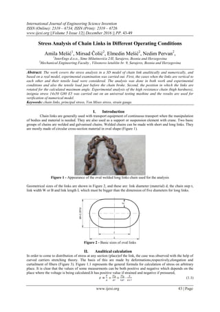
Figure 3 - Section of undeformed link (left) and section of deformed link (right)
where we have:
[MPa] – maximum stress on arbitrary link place,
r – distance from the centre of the link to the central fiber link,
z – distance from the central fiber link to arbitrary fiber,
Mb – maximum momentum offlexion .
Distribution of pressure was conducted under 2α angle and in two end points of the same angle thus being
concentrated in one point of contact. Because of the simetrical nature of geometry one forth of the link is being
analysed which is divided into equal angles. Red lines are showing typical cross-sections (Figure 4).
Figure 4 - Layout of typical cross-sections
Dashed green lines are drawn from central spots of all three fibers where previously calculated stress values
were applied in Excel file. The endpoints are then connected by spline which represent stress diagrams (Figure
5).
Figure 5 - Display of stress diagrams for all angles](data:image/gif;base64,R0lGODlhAQABAIAAAAAAAP///yH5BAEAAAAALAAAAAABAAEAAAIBRAA7)
Recommended
Recommended
More Related Content
What's hot
What's hot (20)
Viewers also liked
Viewers also liked (11)
Similar to Stress Analysis of Chain Links in Different Operating Conditions
Similar to Stress Analysis of Chain Links in Different Operating Conditions (20)
Recently uploaded
Recently uploaded (20)
Stress Analysis of Chain Links in Different Operating Conditions
- 1. International Journal of Engineering Science Invention ISSN (Online): 2319 – 6734, ISSN (Print): 2319 – 6726 www.ijesi.org ||Volume 5 Issue 12|| December 2016 || PP. 43-49 www.ijesi.org 43 | Page Stress Analysis of Chain Links in Different Operating Conditions Amila Mešić1 , Mirsad Čolić2 , Elmedin Mešić2 , Nedim Pervan2 , 1 InterEngs d.o.o., Sime Milutinovića 2/II, Sarajevo, Bosnia and Herzegovina 2 Mechanical Engineering Faculty , Vilsonovo šetalište br. 9, Sarajevo, Bosnia and Herzegovina Abstract: The work covers the stress analysis in a 3D model of chain link analitically and numerically, and based on a real model, experimental examination was carried out. First, the cases when the links are vertical to each other and their tensile load were considered. The analysis was done in both work and experimental conditions and also the tensile load just before the chain broke. Second, the position in which the links are rotated for the calculated maximum angle. Experimental analysis of the high resistance chain (high hardness), insignia stress 14x50 G80 E5 was carried out on an universal testing mashine and the results are used for verification of numerical model. Keywords: chain links, principal stress, Von Mises stress, strain gauge. I. Introduction Chain links are generally used with transport equipment of continuous transport when the manipulation of bodies and material is needed. They are also used as a support or suspension element with crane. Two basic groups of chains are welded and galvanised chains. Welded chains can be made with short and long links. They are mostly made of circular cross-section material in oval shape (Figure 1). Figure 1 - Appearance of the oval welded long links chain used for the analysis Geometrical sizes of the links are shown in Figure 2, and these are: link diameter (material) d, the chain step t, link width W or B and link length L which must be bigger than the dimension of five diameters for long links. Figure 2 - Basic sizes of oval links II. Analitical calculation In order to come to distribution of stress at any section (place)of the link, the case was observed with the help of curved carriers stretching theory. The basis of this are made by deformations,respectively,elongation and curtailment of fibers (Figure 3). Figure 1.1 represents the general formula for calculation of stress on arbitrary place. It is clear that the values of some measurments can be both positive and negative which depends on the place where the voltage is being calculated.It has positive value if strained and negative if pressured, (1.1)
- 2. Stress Analysis of Chain Links in Different Operating Conditions www.ijesi.org 44 | Page Figure 3 - Section of undeformed link (left) and section of deformed link (right) where we have: [MPa] – maximum stress on arbitrary link place, r – distance from the centre of the link to the central fiber link, z – distance from the central fiber link to arbitrary fiber, Mb – maximum momentum offlexion . Distribution of pressure was conducted under 2α angle and in two end points of the same angle thus being concentrated in one point of contact. Because of the simetrical nature of geometry one forth of the link is being analysed which is divided into equal angles. Red lines are showing typical cross-sections (Figure 4). Figure 4 - Layout of typical cross-sections Dashed green lines are drawn from central spots of all three fibers where previously calculated stress values were applied in Excel file. The endpoints are then connected by spline which represent stress diagrams (Figure 5). Figure 5 - Display of stress diagrams for all angles
- 3. Stress Analysis of Chain Links in Different Operating Conditions www.ijesi.org 45 | Page Based on the same data, the diagrams of maximum stress in internal and external fibers were obtained so that the neutral line was constructed (Figure 6). Figure 6 - Neutral line and the diagrams of maximum stress in internal and external fibers III. Numerical Chain Molding Parameterized model of chain segment (Figure 7) used for analysis was obtained in the software package CATIA V5 R20. Because the chain has a breaking force of 160kN, we get the tensile strength with which it is being loaded in working conditions through level of security. If security level is from 3 to 8 we can take value 6 to obtain approximate tensile strength of 26 kN. Figure 7 - 3D model of chain segment The force is equally divaded on two sides of the link so that they will have 13kN by section. In this case the vertical links in working conditions will have stress picture of Von Mises stress like in the figure 3.2, and the values are shown in the middle of the chain (Figure 8). Figure 8 - The value of Von Mises stress in the middle of the link loaded with 26kN The value of stress in the middle of the link with the force of 80 kN increased approximately three times in regards to values obtained with the force of 26 kN (Figure 9).
- 4. Stress Analysis of Chain Links in Different Operating Conditions www.ijesi.org 46 | Page Figure 9 - The value of Von Mises stress in the middle of the link loaded with 80 kN IV. Experimental analysis Electro-resistant measuring tapes (strain gauge) used during voltage analysis of the chain are made of metal foil produced by HBM.Two measuring tapes type 3/120LY11n were used for the analysis, one being active and other compensational. Compensational tape was used because the coefficient of thermal spreading for material DIN/EN 1.6541did not have the same value as tape coefficient. Active measuring tape was set on the active side of the link and compensational on a seperate unloaded clipping of the link in the same chain (Figure 10). Figure 10 - Place with the active and compensational measuring tape After setting measuring tapes on the chain links, the amplifier is being connected to it. The cabel connected to measuring tapes serves for this. When the procedure of connecting the tapes ends the next is setting the segment of the chain on the testing mashine (Figure 11). The segment of testing chain is meant as a part of a chain that has five links regulated by standards for testing high resistant chains. The ending links (upper and lower) are set in the jaws of testing mashine with the help of pins. The links are set vertical to each other so that this analysis could be compared with numerical analysis and analitical calculation. Equipment for the correct and complete analysis is presented in Figure 12. Figure 11 - The chain with strain gauges set in the jaws of testing
- 5. Stress Analysis of Chain Links in Different Operating Conditions www.ijesi.org 47 | Page Figure 12 - Equipment for measuring tapes stress analysis For axial load of the links it is possible to connect Wheatstone bridgeas ¼-bridge with one active and one compensational measuring tape (Figure 13). The principle of action is based on measuring the relative resistance change. If we use the measurment tape resistance change equation, which is based on tape factor equation, we get the equation for calculation of ratio of input and output voltage depending upon the factor of the tape and deformations: (1.2) Figure 13 - Connection in ¼ bridge with compensational measuring tapem Since we use compensational measure tape (Figure 14) in Wheatstone bridgeas the neutralisation of thermal influence would take place . In this way the changed deformation would only be equal to deformation under load ie.: (1.3) Figure 14 - Electrical scheme of connection of Viston bridge
- 6. Stress Analysis of Chain Links in Different Operating Conditions www.ijesi.org 48 | Page The output voltage is being calculated for this case from the expression: (1.4) By changing the force of tightening on test mashine, the software registers the change in deformation size. For the first case of the load, examination started with the force of 1kN and was monitored all the way to the force of tightening in working conditions (26kN) as performed by FEM analysis. The sizes of deformations arein μm/m, so that it was possible to calculate the value of voltage for each deformation by using Hook's law. V. Results In Table 1, the results of stress analysis with strain gauges are presented. Since that the size of the force of 26 kN here matters, the stress in this place was calculated as: Table 1 - Results of stress analysis with measure tapes – the load from 1 kN to 26 k N Force [kN] Deformation [μm/m] Stress [MPa] 1 67 14,07 2 117 24,57 ⁞ ⁞ ⁞ 25 1305 274,05 26 1340 281,40 Based on the readings of the values during measurment (Table 1), a diagram of change of deformation was charted depending on the force change (Figure 15). It can be seen from the same figure that a diagram is a straight line meaning the deformation is directly proportional to the force of tightening . Figure 15 - Diagram of deformations dependance from the force Based on the same principle the readings of deformations was conducted for chain loads with the force of 30 kN to 80 kN, with a step from 5 kN. The results of all three methods of stress analysis for loads in working conditions are shown in Table 2. Table 2 - Stress analysis results comperison– the load from 1 kN to 26 k N Analysis of stress Value Analitical 299,46 MPa Numerical 283 MPa Strain gauges 281,40 MPa Deviation analitical – numerical 5,49% Deviation analitical – strain gauges 6,03% Deviation numerical – strain gauges 0,57% When we take into account the loads from 30 kN to 80 kN, the values of stress presented in table 3 will be obtained.
- 7. Stress Analysis of Chain Links in Different Operating Conditions www.ijesi.org 49 | Page Table 3 - Stress analysis result comparison– load from 30 kN to 80 k N Stress analysis Value Analitical 299,46 MPa Numerical 283 MPa Strain gauges 281,40 MPa Deviation analitical – numerical 5,49% Deviation analitical – strain gauges 6,03% Deviation numerical – strain gauges 0,57% VI. Conclusion The aim of this work was the analysis of stress in high resistant chain links 14x50 G80 E5, which is in use in brown coal mines all over Bosnia and Herzegovina. The terms are derived for calculation of stress at any place of section for different cases of divison of pressure analitically. The presentation of stress diagrams was conducted based on what the neutral lines were constructed. After forming a model numerical analysis was conducted for working conditions with a load of 26 kN where the links are vertically set in regard to each other. Beside all this, a segment of chain set like this was examined with the load of 80 kN which is defined by the manufacturorexamination force.The third case of numerical analysis for vertically set links refers to the load which the chain undergoes just before breacking. The value of the forse was 242 kN then. The chain has completaly deformed which is described in this work in more detail. Numerical analysis is not based only on ideal positions of links but it expands further on real cases which causes the links to rotate. Positions of the rotated links are also examined for loads under working and examination conditions. Stress analysis with strain gauges was also conducted which is very important because of comparison of results validity.There are almost no deviations of result values obtained numerically from the analysis results obtained by measuring tapes. For chain load with 26 kN they are 0.57%, while the deviations for loads with 80 kN only 0.27%.When compared, analitical and numerical results and analitical with strain gauges, we can say that the deviations are below allowed limits of 10% because they are in interval from 5.32% to 6.03%. We can finally conclude that the analysed chain can endure, without any problems, the loads prescribed by the manufactoror. References [1] N.Repčić, M.Čolić, Transportna sredstva, Faculty of Mechanical Engineering, Sarajevo, 2008. [2] A.Muminović, I.Šarić, E.Mešić, Konstruisanje podržano računarima, Faculty of Mechanical Engineering, Sarajevo, 2012. [3] G.A.Goodenough, L.E.Moore, The Strength od Chain Links, University of Illinois, Bulletin No. 18, Illinois, 1907. [4] E.Bjørnsen, Chain in Mooring Systems, Norwegian University of Science and Technology, Department of Structural Engineering, NTNU-Trondheim, 2014. [5] V.Doleček, I. Karabegović, D. Martinović, D. Blagojević, B. Šimun, D. Vukojević, Dž. Kudumović, N. Uzunović Zaimović, I. Bijelonja, Elastostatika. Dio 1, Faculty of Engineering Bihać, Bihać, 2003. [6] N.Pervan, M. Čolić, I. Šarić, V. Hadžiabdić, Analysis of the Haulage Ropes on Ropeways in Case of Accidental Loads, TEM Journal, Vol.5., No.2., 171-174, 2016. [7] N.Pervan, E. Mešić, M. Čolić, V. Avdić, Stiffness Analysis of the Sarafix External Fixator of Composite Material., International Journal of Engineering & Technology, Vol. 5., No.1., 20-24, 2016. [8] E. Mešić, V. Avdić, N. Pervan, Numerical and experimental stress analysis of an external fixation system, Folia Medica, Facultatis Medicinae Universitatis Saraeviensis, Vol.50, No.1., 74-80, 2015.