96 manuscript-579-1-10-20210211

Passivity Based Control for PV Applications by Using a Buck Power Converter The use of power converters for everyday applications is becoming more and more important. Current technological applications simultaneously demand a high level of precision and performance, so DC-DC converters have a very important role in systems requiring energy level conversion and adaptation. As part of the work of this paper, we are interested in an analysis of modeling and control law synthesis approaches to ensure stability and a certain level of performance in the entire operating domain. The objective of our research work is therefore to propose a control law whose synthesis is based on a formalized (modeling & control) approach with a view to obtaining a control law adapted to the operating point. The principles used are based on the control and observation by the theory of passivity for the synthesis of control law of buck power converter for PV Applications.

Recommended
Recommended
More Related Content
What's hot
What's hot (20)
Similar to 96 manuscript-579-1-10-20210211
Similar to 96 manuscript-579-1-10-20210211 (20)
More from Mellah Hacene
More from Mellah Hacene (20)
Recently uploaded
Recently uploaded (20)
96 manuscript-579-1-10-20210211
- 1. a iKSP Journal of Computer Science and Engineering http://iksp.org/journals/index.php/ijcse/index © iKSP Publisher Passivity Based Control for PV Applications by Using a Buck Power Converter Rachid Taleb*1 ,1 Maamar Souaihia1 , Abdelhadi Namoune2 , Hacene Mellah1 1 Electrical Engineering Department, Hassiba Benbouali University, Chlef, Algeria Laboratoire Génie Electrique et Energies Renouvelables (LGEER) 2 Electrical Engineering Department, Ahmed Zabana University Centre, Relizane, Algeria _______________________________________________________________________________________________ Abstract - The use of power converters for everyday applications is becoming more and more important. Current technological applications simultaneously demand a high level of precision and performance, so DC-DC converters have a very important role in systems requiring energy level conversion and adaptation. As part of the work of this paper, we are interested in an analysis of modeling and control law synthesis approaches to ensure stability and a certain level of performance in the entire operating domain. The objective of our research work is therefore to propose a control law whose synthesis is based on a formalized (modeling & control) approach with a view to obtaining a control law adapted to the operating point. The principles used are based on the control and observation by the theory of passivity for the synthesis of control law of buck power converter for PV Applications. Keywords: Passivity Control, Buck Power Converter, PV, Simulation. _______________________________________________________________________________________________ INTRODUCTION The DC-DC switching converter works to periodically switch several operating modes. Due to the activation and deactivation of the switch, the converter is discrete although each mode of operation is linear and continuous. As a whole, the converter is a strongly nonlinear system. Compared to the linear method based on classical control theory, the nonlinear method for controlling the converter is more advantageous, and Passivity theory is an analytical technique for controlling nonlinear system (Wang et al., 2019), (Khaligh et al., 2006), (Shet, 2006), (Singh & Pandey, 2016). In most cases, a photovoltaic solar generator is not properly suited to an electrical load. Usually an adaptation stage, comprising one or more static converters, makes it possible to transform continuous electrical quantities into quantities adapted to the load. This stage can be controlled by one or more control laws in order to maximize the power produced by the generator. In this work, Passivity control (PC) is applied for the purpose of tracking the MPP of the solar photovoltaic system. The electrical characteristic of the GPV which is approximated by a nonlinear model. The PC for controlling the Buck converter. Then the PI command is applied for the purpose of tracking the MPP of the same system. Finally we make a comparison for the two commands (Rakshit & Maity, 2018), (Sher et al., 2015), (Ryu et al., 2018), (Latif & Hussain, 2014). Passivity control of buck converter The DC-DC switching converter works to periodically switch several operating modes. Due to the activation and deactivation of the switch, the converter is discrete although each mode of operation is linear and continuous. As a whole, the converter is a strongly nonlinear system. Compared with the linear method based on the classical control theory, the nonlinear method for controlling the converter is more advantageous, and the passivity theory is an analytical technique for controlling nonlinear system (Chuanjiang et al., 2006), (Zhang et al., 2018), (Kang et al., 2013), (Zhitao et al., 2010). 1 *Corresponding author: Email: rac.taleb@gmail.com (R. Taleb) iKSP Journal of Computer Science and Engineering (2021) 1(2): 26-31
- 2. iKSP Journal of Computer Science and Engineering (2021) 1(2): 26-31 27 In general there are two different approaches, both based on the energy point of view, in order to model DC/DC converters in switching. The first approach uses the Lagrangian of the system while the second uses the Hamiltonian. Note that these methods are a priori very general and can also be used for the modeling of mechanical systems for example. Each of these models will allow us to apply the various control law synthesis methods using the tools of passivity. In this section we present the Euler-Lagrange model (Zhang et al., 2018; (Malik et at., 2019). In this section, we will introduce from a theoretical point of view, two classical methods for the synthesis of control laws, both based on passivity: The DI method and the IDAPBC method. In our work we use the DI method. Consider a system whose general state model, Euler-Lagrange model, is of the form: 𝒟𝑥̇ − ℐ𝑥 + ℛ𝑥 = ℰ (1) Where D is diagonal, J is antisymmetric and R is symmetric positive semi-definite, corresponding to the average Euler- Lagrange model. The purpose of the control law is to regulate the output of the system to a desired constant value. The methodology of the passivity control consists in making the closed loop (strictly) passive characterized by a desired storage function Hd. We consider that a storage function of the system can be chosen according to the form 𝐻 = 1 2 𝑥𝑇 𝐷𝑥, which turns out to be the total energy of the lossless average model of the converter. Then we can offer as the desired storage function: 𝐻𝑑 = 1 2 𝑥 ̃𝑇 𝐷𝑥 ̃ (2) Where 𝑥 ̃ ≔ 𝑥 − 𝑥𝑑 with 𝑥𝑑 the desired value of x to be defined. Thus, by posing in (1): 𝑥 = 𝑥 ̃ + 𝑥𝑑 (3) 𝑅 = 𝑅𝑑 − 𝐻𝐷𝐼 (4) Where Rd represents the desired damping, the dynamics of the error x ̃ of the system associated with the storage function (2) will be: 𝐷𝑥 ̃̇ − 𝐽𝑥 ̃ + 𝑅𝑑𝑥 ̃ = 𝐸 − (𝐷𝑥̇𝑑 − 𝐽𝑥𝑑 + 𝑅𝑥𝑑) + 𝑅𝐷1𝑥 ̃ = 𝜓 (5) This dynamic is obtained after having injected the necessary damping 𝑅𝐷1 so that 𝑅𝑑 = 𝑅 + 𝑅𝐷1 is symmetrical definite positive. However, having a positive definite damping matrix, it is possible to make the closed loop strictly passive by taking ψ = 0. The dynamics: 𝐷𝑥 ̃̇ − 𝐽𝑥 ̃ + 𝑅𝑑𝑥 ̃ = 0 (6) Will therefore be exponentially stable, because by taking the time derivative of 𝐻𝒅 along the solutions of (5), since J is antisymmetric, we obtain: 𝐻̇𝑑 = −𝑥 ̃𝑇 𝑅𝑑𝑥 ̃ ≤ −𝛼𝐻𝑑 < 0 ∀𝑥 ̃ ≠ 0 (7) Because 𝑅𝑑 and D are two diagonal matrices with positive coefficients. It is then enough to fix ψ = 0 to obtain the dynamics of the control law, which gives: 𝐷𝑥̇𝑑 − 𝐽𝑥𝑑 + 𝑅𝐷1𝑥 ̃ = 𝐸 (8) Equation (7) then gives us an implicit definition of the control law. To obtain an explicit definition and since the command u is present in the matrix J or the vector E, we must then solve a system of n equations with n + 1 unknowns. Thus, it will be necessary to choose one of the state variables of the system to set in order to be able to explicitly define the control law at u. This procedure will be illustrated below in the context of the application to DC-DC converters. We will also see that the application of this method could lead, according to the fixed state variable, to instabilities of the control law, to equilibrium or even to too great a complexity, in particular for high order systems.
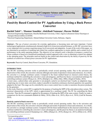
- 3. iKSP Journal of Computer Science and Engineering (2021) 1(2): 26-31 28 In this section, we will apply the passivity-based control law synthesis methods for the DC-DC converter type (Buck). We will then show the performances obtained with this control law in simulation for this type of converter. The Euler-Lagrange mean state model for the Buck converter (Fig 1) is: Figure 1: Buck converter diagram ( 𝐿 0 0 𝐶 ) 𝑥̇ = ( 0 −1 1 − 1 𝑅 ) 𝑥 + 𝑢 ( 𝐸 0 ) (9) Obtained by following the modeling method presented in section (9) the expression of the control law by the DI (damping injection) method then gives us the following system of equations, obtained by exploiting the relation (7): 𝜓 = 0 ⇔ { 𝐿𝑥̇1𝑑 + 𝑥2𝑑 − 𝑅1(𝑥1 − 𝑥1𝑑) = 𝑢𝐸 𝐶𝑥̇2𝑑 − 𝑥1𝑑 + 1 𝑅 𝑥2𝑑 = 0 (10) For a matrix: 𝑅𝐷𝐼 = ( 𝑅1 0 0 0 ) (11) If we fix 𝑥2𝑑 = 𝑥2 ∗ with 𝑥2 ∗ = 𝑣𝐶𝑑 reference output voltage (assumed constant), we get the control law: 𝑢 = 𝑣𝐶𝑑−𝑅1(𝑥1− 𝑣𝐶𝑑 𝑅 ) 𝐸 (12) In the case of our study, we limit ourselves to the classic PI controller technique which successfully satisfies the control regulation of systems from the point of view of stability, speed and precision. The parameters of the Buck converter are given by Table 1. Table 1. Buck Converter Parameters L C E R R1 220 𝜇𝐻 47 𝜇𝐹 20 11Ω 3Ω The results of the simulation show that the response time and the speed of the passivity controlled buck converter (PC) are better in transient mode compared to the PI regulator, we can also say that the static error for both controls is acceptable. We notice that in general the performances of the passivity are better than those of the regulator
- 4. iKSP Journal of Computer Science and Engineering (2021) 1(2): 26-31 29 Figure 2: Output voltage (V) Figure 3: Current (A) Passivity based MPPT control of buck converter In most cases, a photovoltaic solar generator is not properly suited to an electrical load. Usually an adaptation stage, comprising one or more static converters, makes it possible to transform continuous electrical quantities into quantities adapted to the load. This stage can be controlled by one or more control laws in order to maximize the power produced by the generator. In this chapter, Passivity control (PC) is applied for the purpose of tracking the MPP of the solar photovoltaic system. The electrical characteristic of the GPV which is approximated by a nonlinear model. The PBC for controlling the BUCK converter. Then the PI regulator is applied for the purpose of tracking the MPP of the same system. Finally we make a comparison for the two commands. There is an operating point where the power output is maximum (figure 4). The optimization consists in achieving this point permanently by acting automatically on the load seen by the generator this load adaptation in principle is generally carried out using a static converter in the losses must be as low as possible and which can, moreover, perform a shaping function of an output generator, different attitudes can be envisaged as regards the control of the adapter. Figure 4: Power characteristic curve of GPV Time (s) Time (s)
- 5. iKSP Journal of Computer Science and Engineering (2021) 1(2): 26-31 30 In the literature, we can find different types of algorithms performing the search for PPM. In our work we are interested in the Perturb & Observ (P&O) method; we briefly recall the principle of this method. Figures 5 and 6 show the effect of increasing the power, caused by an increase in irradiation, which generates a deviation of the maximum power point MPP for both controls the voltage, is almost constant. Once the irradiation stabilizes, the power returns to its stable state with fewer disturbances to the passivity. The latter made it possible to obtain a very short response time and better dynamic performance with negligible disturbances compared to a PI regulator Figure 5: Power (W) Figure 6: Output voltage (V) Figures 7 and 8 show that the increase in temperature implies a decrease in the maximum power for the two controls with decrease in the voltage, which causes a displacement of the point of maximum power. Stabilizes, the power returns to its stable state. Figure 7: Power (W) Time (s) Time (s) Time (s)
- 6. iKSP Journal of Computer Science and Engineering (2021) 1(2): 26-31 31 Figure 8: Output voltage (V) CONCLUSION We have presented in this work MPPT Control Based on Passivity and MPPT Control on the PI regulator. Finally, the application of the passivity control (PC) for the pursuit of the MPP shows its efficiency and its robustness compared to the PI regulator in terms of the speed and the reduction of the disturbances vis-à-vis climatic variations as well only system settings. REFERENCES Chuanjiang Li, Guangfu Ma and Bin Song, "Passivity-based Nonlinear Attitude Regulation of Rigid Spacecraft Subject to Control Saturation," 2006 6th World Congress on Intelligent Control and Automation, Dalian, 2006, pp. 8421- 8425. Kang X. Lv, Z. and Y. Mei, "Double dq control strategy of DFIG based on passivity theory under unbalanced grid voltage," Proceedings of the 32nd Chinese Control Conference, Xi'an, 2013, pp. 8851-8856. Khaligh A., A. M. Rahimi, M. Khaligh and A. Emadi, "Sensitivity Analyses of Pulse Adjustment Control Technique of a Buck-Boost Converter Operating in Discontinuous Conduction Mode and Driving Constant Power Loads," 2006 IEEE Vehicle Power and Propulsion Conference, Windsor, 2006, pp. 1-5. Latif T. and S. R. Hussain, "Design of a charge controller based on SEPIC and buck topology using modified Incremental Conductance MPPT," 8th International Conference on Electrical and Computer Engineering, Dhaka, 2014, pp. 824-827. Malik, H. A. M., Mahmood, N., Usman, M. H., Rziwan, K., & Abid, F. (2019). Analysis of Airport Network in Pakistan Utilizing Complex Network Approach. Network, 10(1). Rakshit S. and J. Maity, "Three Phase, 10 kVA Dual Conversion type Automatic AC Voltage Regulator - An Approach based on Fuzzy Logic Controlled Ćuk Converter and PI Controlled Three Phase Inverter," 2018 IEEE 8th Power India International Conference (PIICON), Kurukshetra, India, 2018, pp. 1-6. Ryu D., Y. Kim and H. Kim, "Optimum MPPT Control Period for Actual Insolation Condition," 2018 IEEE International Telecommunications Energy Conference (INTELEC), Turin, 2018, pp. 1-4. Sher H. A., A. F. Murtaza, A. Noman, K. E. Addoweesh, K. Al-Haddad and M. Chiaberge, "A New Sensorless Hybrid MPPT Algorithm Based on Fractional Short-Circuit Current Measurement and P&O MPPT," in IEEE Transactions on Sustainable Energy, vol. 6, no. 4, pp. 1426-1434, Oct. 2015. Shet V. N., "Resonant Operated Buck Converter with Reduced Device Switching Stress with Power Factor Improvement," 2006 International Conference on Power Electronic, Drives and Energy Systems, New Delhi, 2006, pp. 1-6. Singh B. and R. Pandey, "Improved power quality buck-boost converter fed LLC resonant converter for induction heater," 2016 IEEE 6th International Conference on Power Systems (ICPS), New Delhi, 2016, pp. 1-6. Wang W., R. Wei and Y. Yin, "Efficiency-based power MOSFETs size optimization method for DC-DC buck converters," 2019 20th International Symposium on Power Electronics (Ee), Novi Sad, Serbia, 2019, pp. 1-5 Zhang M., P. Borja, R. Ortega, Z. Liu and H. Su, "PID Passivity-Based Control of Port-Hamiltonian Systems," in IEEE Transactions on Automatic Control, vol. 63, no. 4, pp. 1032-1044, April 2018. Zhitao Liu, Hongye Su and Shuwen Pan, "Passivity-based adaptive integral sliding mode control of uncertain nonlinear systems," 2010 8th World Congress on Intelligent Control and Automation, Jinan, 2010. Time (s)