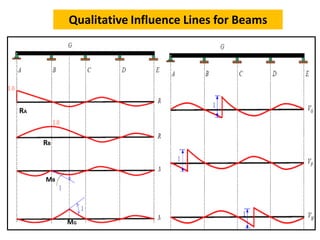
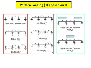
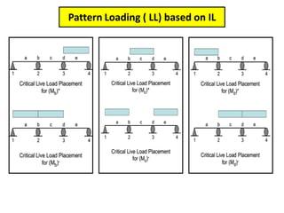
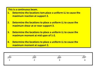
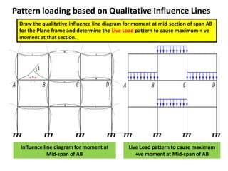
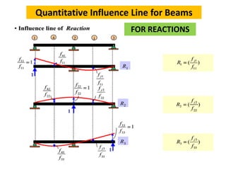
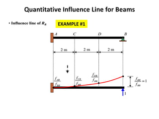
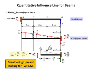
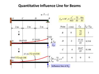
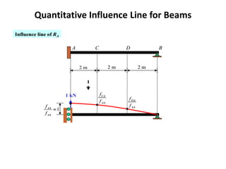
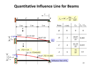
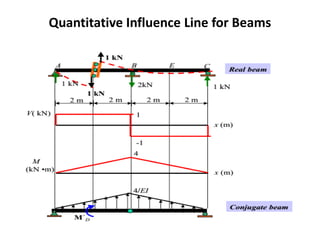
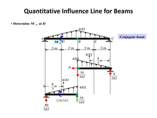
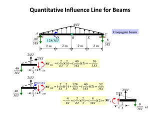
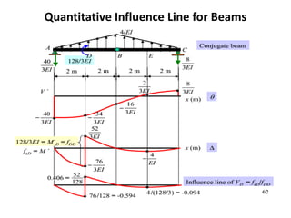
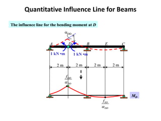
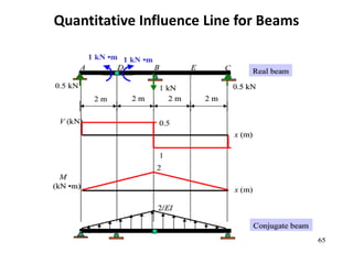
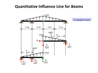
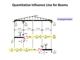
Influence Lines for
Indeterminate Beams and Frames
QUESTION
Where should a structural engineer place the live load on the
structure so that it creates the maximum response at a specified
point or section?
Ability to obtain the influence lines for statically
indeterminate structures, beams and building frames
Prof. Dr. Md. Jahangir Alam
CUET
Definition of Influence Line
INFLUENCE LINES
Variation of Reaction, Shear, Moment or Deflection at a SPECIFIC POINT due to a
concentrated force moving on beam or frames.
Applying a deformation to a statically determinate beam or frame will not
cause the beam or frame to bend. The deflected shape due to the unit deformation
will be composed of straight lines and can be used to locate the movable loads to
cause maximum effect, and to calculate the magnitude of the force. Such an
influence diagram is called a quantitative influence line for a determinate structure.
Applying a deformation to a statically indeterminate beam or frame
will cause the structure to bend and can only be used to locate the position of
movable loads (like Live load ) to cause maximum response.
Comparison Between Indeterminate and Determinate Beams
Indeterminate Beam Determinate Beam
Comparison Between Indeterminate and Determinate Beams
Qualitative Influence Lines
Müller-Breslau Principle
The Müller-Breslau principle is a method to determine influence
lines. The derivation of the principle comes from the theory
of Virtual work.
Statement:
The influence line for a response function (reaction, shear,
moment or deflection) is given by the deflected shape of the
released structure by removing the displacement constraint
corresponding to the response function of interest from the original
structure and giving a unit displacement or rotation at the location
and in the direction of the response function.
Procedure for constructing qualitative IL
Procedure for constructing qualitative influence
lines for indeterminate structures is:
 Remove from the structure the restraint
corresponding to the response function of interest.
 Apply a unit displacement or rotation to the
released structure at the release in the desired
response function direction, and
Draw the qualitative deflected shape of the
released structure consistent with all remaining
support and continuity conditions.
Qualitative IL for Shear at a section
 To determine the qualitative influence line for the shear of a
section, remove the shear resistance of the beam at this
section by inserting a roller guide, i.e., a support that does not
resist shear, but maintains axial force and bending moment
resistance.
 Removing the shear resistance will then allow the ends on
each side of the section to move perpendicular to the beam
axis of the structure at this section.
 Next, apply a unit shear force that will result in the relative
vertical displacement between the two ends to equal unity.
 The magnitude of these forces are proportional to the
location of the section and the span of the beam
Qualitative IL for moment at a section
 To obtain a qualitative influence line for the bending moment
at a section, remove the moment restraint at the section, but
maintain axial and shear force resistance.
 The moment resistance is eliminated by inserting a hinge in
the structure at the section location.
 Apply equal and opposite moments respectively on the right
and left sides of the hinge that will introduce a unit relative
rotation between the two tangents of the deflected shape at
the hinge.
 The corresponding elastic curve for the beam, under these
conditions, is the influence line for the bending moment at
the section.
Qualitative IL for reaction, shear and moment
Qualitative Influence Lines for Beams
RA
RB
MB
MG
Where should a structural engineer place the live load on the
structure (Beam or Frame) so that it creates the maximum
response at a specified point or section?
Live Load Pattern to Maximize Member Forces in
Multistory Buildings
• Building Codes specify that structural members of
multistory buildings be designed to support a
uniformly distributed Live Load as well as Dead Load of
the structure.
• Dead Load and Live Load are normally considered
separately since the DL is fixed in position whereas LL
must be varied to maximize a particular force at each
section of the structure. Such maximum forces are
typically produced by Pattern Loading.
Pattern loading of Live Load(LL)
• Based on the qualitative influence lines,
critical LL placement can be determined.
• A structural analysis computer program can be
used to calculate the member end shear and
moments for the DL and critical LL cases.
Pattern Loading ( LL) based on IL
This is a continuous beam.
1. Determine the locations tom place a uniform LL to cause the
maximum reaction at support 2.
2. Determine the locations to place a uniform LL to cause the
maximum shear at or near support 3.
3. Determine the locations to place a uniform LL to cause the
maximum moment at mid span of 1-2.
4. Determine the locations to place a uniform LL to cause the
maximum moment at support 2.
Pattern Loading
Pattern Loading based on Qualitative Influence Lines
Draw the qualitative influence line diagram for shear at section 1-1 for the Plane frame
and determine the load pattern to cause maximum + ve and maximum – ve shear at
section 1-1.
Shear at a section
Pattern Loading based on Qualitative Influence Lines
Draw the qualitative influence line diagram for moment at section 1 for the Plane frame
and determine the load pattern to cause maximum + ve and maximum – ve moment at
section 1.
Moment at section 1
Pattern loading based on Qualitative Influence Lines
Draw the qualitative influence line diagram for moment at mid-section of span AB
for the Plane frame and determine the Live Load pattern to cause maximum + ve
moment at that section.
Influence line diagram for moment at
Mid-span of AB
Live Load pattern to cause maximum
+ve moment at Mid-span of AB
Pattern loading based on Qualitative Influence Lines
Column Vertical Reaction
&
Column Moment
Beam Mid-span Moment Beam End Moment
Quantitative
Influence Lines for Beam
Quantitative Influence Line for Beams
FOR REACTIONS
Quantitative Influence Line for Beams
EXAMPLE #1
Quantitative Influence Line for Beams
Considering Upward
loading for +ve B.M.
Quantitative Influence Line for Beams
Considering downward
loading for -ve B.M.
Quantitative Influence Line for Beams
Considering Upward
loading for +ve B.M.
Quantitative Influence Line for Beams
Example # 3
Quantitative Influence Line for Beams
Example # 4
End of this topic

Influence lines for_indeterminate_beams_and_frames

  • 1.
    Influence Lines for IndeterminateBeams and Frames QUESTION Where should a structural engineer place the live load on the structure so that it creates the maximum response at a specified point or section? Ability to obtain the influence lines for statically indeterminate structures, beams and building frames Prof. Dr. Md. Jahangir Alam CUET
  • 2.
    Definition of InfluenceLine INFLUENCE LINES Variation of Reaction, Shear, Moment or Deflection at a SPECIFIC POINT due to a concentrated force moving on beam or frames. Applying a deformation to a statically determinate beam or frame will not cause the beam or frame to bend. The deflected shape due to the unit deformation will be composed of straight lines and can be used to locate the movable loads to cause maximum effect, and to calculate the magnitude of the force. Such an influence diagram is called a quantitative influence line for a determinate structure. Applying a deformation to a statically indeterminate beam or frame will cause the structure to bend and can only be used to locate the position of movable loads (like Live load ) to cause maximum response.
  • 4.
    Comparison Between Indeterminateand Determinate Beams Indeterminate Beam Determinate Beam
  • 5.
    Comparison Between Indeterminateand Determinate Beams
  • 6.
    Qualitative Influence Lines Müller-BreslauPrinciple The Müller-Breslau principle is a method to determine influence lines. The derivation of the principle comes from the theory of Virtual work. Statement: The influence line for a response function (reaction, shear, moment or deflection) is given by the deflected shape of the released structure by removing the displacement constraint corresponding to the response function of interest from the original structure and giving a unit displacement or rotation at the location and in the direction of the response function.
  • 7.
    Procedure for constructingqualitative IL Procedure for constructing qualitative influence lines for indeterminate structures is:  Remove from the structure the restraint corresponding to the response function of interest.  Apply a unit displacement or rotation to the released structure at the release in the desired response function direction, and Draw the qualitative deflected shape of the released structure consistent with all remaining support and continuity conditions.
  • 8.
    Qualitative IL forShear at a section  To determine the qualitative influence line for the shear of a section, remove the shear resistance of the beam at this section by inserting a roller guide, i.e., a support that does not resist shear, but maintains axial force and bending moment resistance.  Removing the shear resistance will then allow the ends on each side of the section to move perpendicular to the beam axis of the structure at this section.  Next, apply a unit shear force that will result in the relative vertical displacement between the two ends to equal unity.  The magnitude of these forces are proportional to the location of the section and the span of the beam
  • 9.
    Qualitative IL formoment at a section  To obtain a qualitative influence line for the bending moment at a section, remove the moment restraint at the section, but maintain axial and shear force resistance.  The moment resistance is eliminated by inserting a hinge in the structure at the section location.  Apply equal and opposite moments respectively on the right and left sides of the hinge that will introduce a unit relative rotation between the two tangents of the deflected shape at the hinge.  The corresponding elastic curve for the beam, under these conditions, is the influence line for the bending moment at the section.
  • 10.
    Qualitative IL forreaction, shear and moment
  • 11.
  • 12.
    Qualitative Influence Linesfor Beams RA RB MB MG
  • 13.
    Where should astructural engineer place the live load on the structure (Beam or Frame) so that it creates the maximum response at a specified point or section? Live Load Pattern to Maximize Member Forces in Multistory Buildings • Building Codes specify that structural members of multistory buildings be designed to support a uniformly distributed Live Load as well as Dead Load of the structure. • Dead Load and Live Load are normally considered separately since the DL is fixed in position whereas LL must be varied to maximize a particular force at each section of the structure. Such maximum forces are typically produced by Pattern Loading.
  • 14.
    Pattern loading ofLive Load(LL) • Based on the qualitative influence lines, critical LL placement can be determined. • A structural analysis computer program can be used to calculate the member end shear and moments for the DL and critical LL cases.
  • 15.
    Pattern Loading (LL) based on IL
  • 16.
    Pattern Loading (LL) based on IL
  • 17.
    This is acontinuous beam. 1. Determine the locations tom place a uniform LL to cause the maximum reaction at support 2. 2. Determine the locations to place a uniform LL to cause the maximum shear at or near support 3. 3. Determine the locations to place a uniform LL to cause the maximum moment at mid span of 1-2. 4. Determine the locations to place a uniform LL to cause the maximum moment at support 2.
  • 18.
  • 19.
    Pattern Loading basedon Qualitative Influence Lines Draw the qualitative influence line diagram for shear at section 1-1 for the Plane frame and determine the load pattern to cause maximum + ve and maximum – ve shear at section 1-1. Shear at a section
  • 20.
    Pattern Loading basedon Qualitative Influence Lines Draw the qualitative influence line diagram for moment at section 1 for the Plane frame and determine the load pattern to cause maximum + ve and maximum – ve moment at section 1. Moment at section 1
  • 21.
    Pattern loading basedon Qualitative Influence Lines Draw the qualitative influence line diagram for moment at mid-section of span AB for the Plane frame and determine the Live Load pattern to cause maximum + ve moment at that section. Influence line diagram for moment at Mid-span of AB Live Load pattern to cause maximum +ve moment at Mid-span of AB
  • 22.
    Pattern loading basedon Qualitative Influence Lines Column Vertical Reaction & Column Moment Beam Mid-span Moment Beam End Moment
  • 23.
  • 24.
    Quantitative Influence Linefor Beams FOR REACTIONS
  • 25.
    Quantitative Influence Linefor Beams EXAMPLE #1
  • 26.
    Quantitative Influence Linefor Beams Considering Upward loading for +ve B.M.
  • 27.
  • 28.
  • 29.
    Quantitative Influence Linefor Beams Considering downward loading for -ve B.M.
  • 30.
  • 31.
  • 32.
  • 33.
    Quantitative Influence Linefor Beams Considering Upward loading for +ve B.M.
  • 34.
  • 35.
  • 36.
    Quantitative Influence Linefor Beams Example # 3
  • 37.
  • 38.
  • 39.
  • 40.
  • 41.
  • 42.
  • 43.
  • 44.
  • 45.
  • 46.
  • 47.
  • 48.
  • 49.
    Quantitative Influence Linefor Beams Example # 4
  • 50.